Week 10: Machine Building
✓ design a machine that includes mechanism+actuation+automation+application
✓ build the mechanical parts and operate it manually
✓ actuate and automate your machine
✓ document the group project and your individual contribution
The full documentation for our machine can be found here
Machine Dismantling
We started this week by dismantling a printer that was given to the Fablab. It was a very interesting process and we discovered and learnt many things.
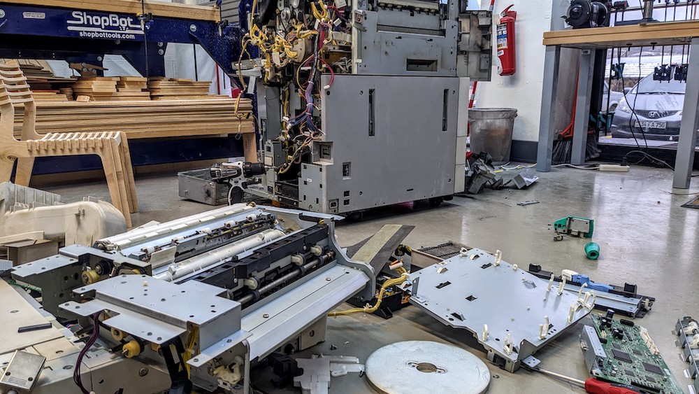
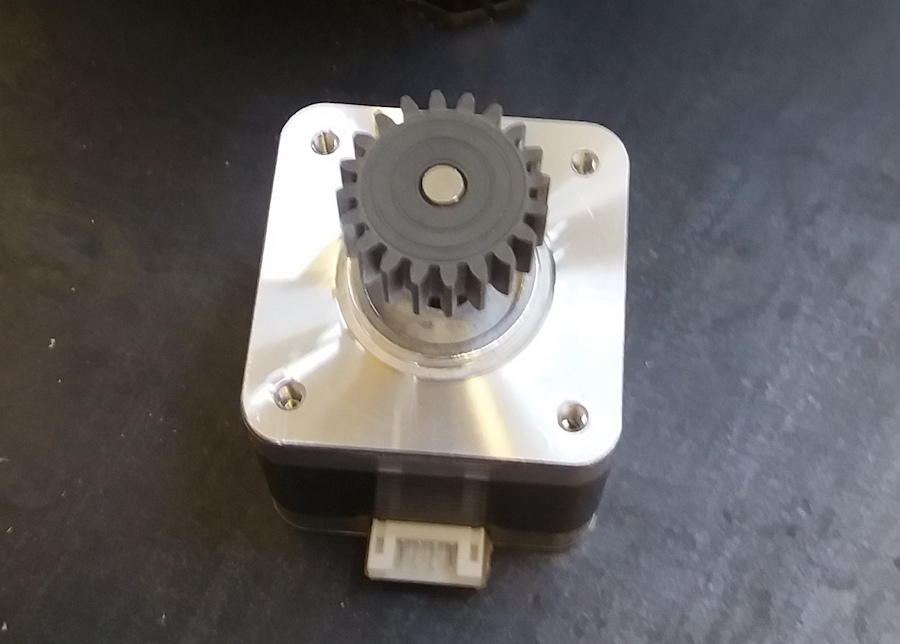
One of the most precious parts to recover were the stepper motors.

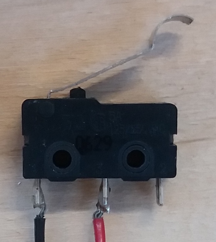
Switches
In the printer, we found some mechanical switches, which trigger when the metallic part is pushed:
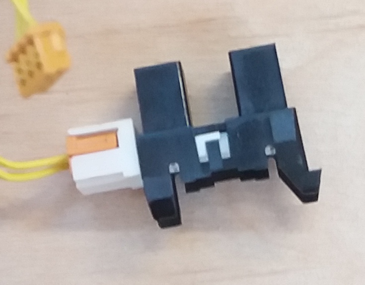
and also some magnetic switches:
Buttons
We learnt about Normally Open (NO) and Normally Closed (NC) mechanism in buttons. The default state of the NO button is an open circuit, where no current is flowing, and in an NC button, the default state is a closed circuit, where the current can flow. Some buttons have the possibility to choose which default state we want:
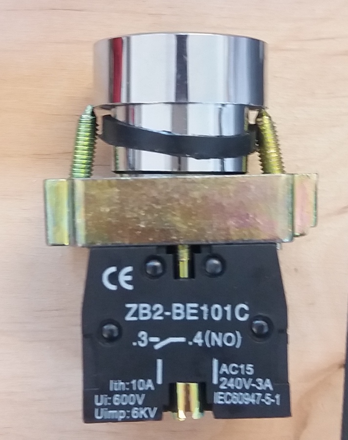
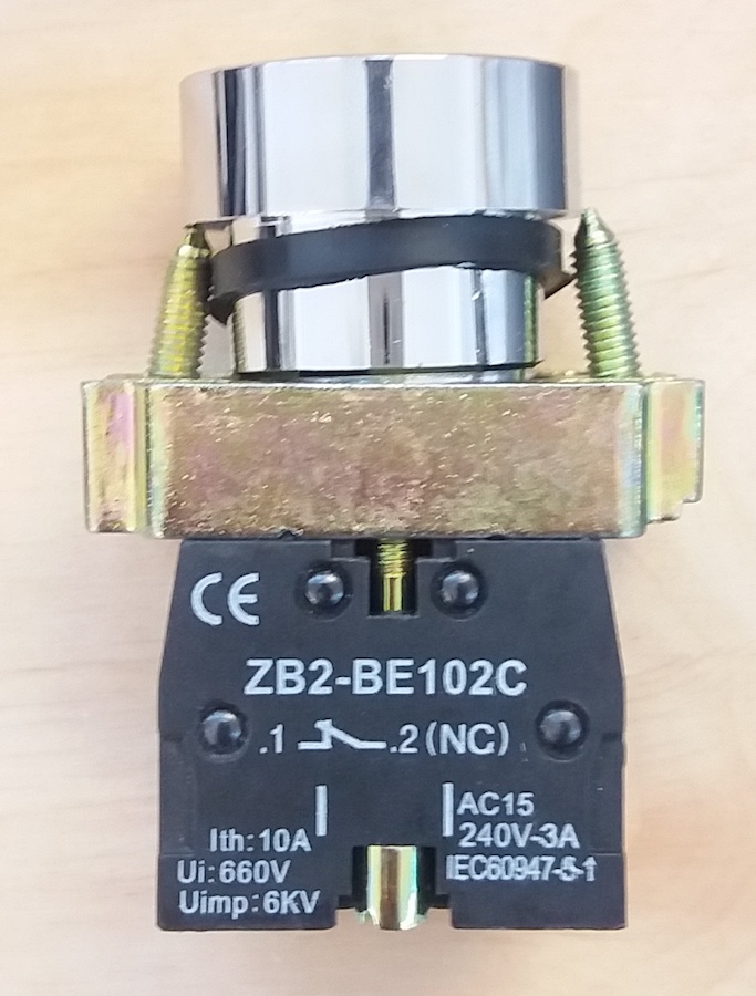
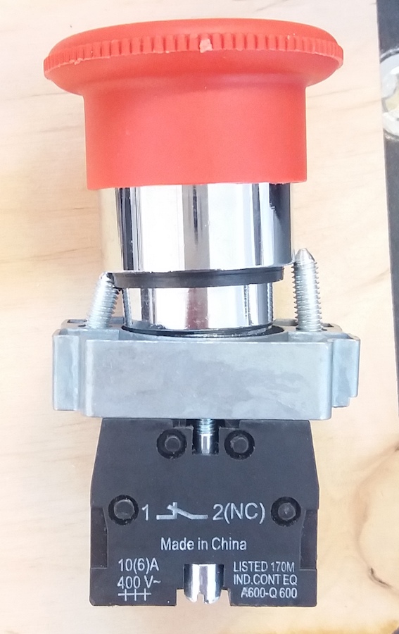
For safety button, the default state should always be closed, so that the button triggers in case of failure of its circuit:
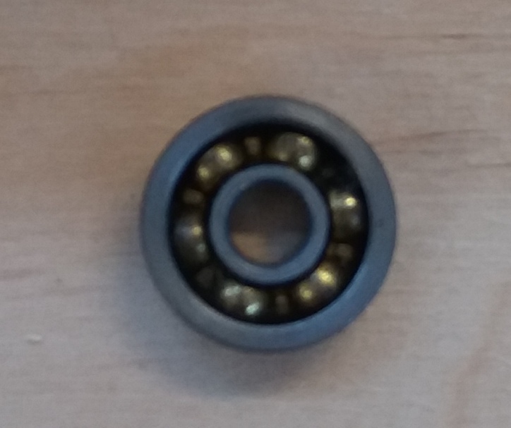
Bearings
- radial bearing: designed to sustain forces applied perpendicular to the axis of rotation
- thrust bearing: designed to sustain forces applied parallel to the axis of rotation
- friction bearing: no balls, just lubricant
- tapered roller bearing: designed to sustain forces applied perpendicular to the axis of rotation, as well as one direction parallel to this axis.
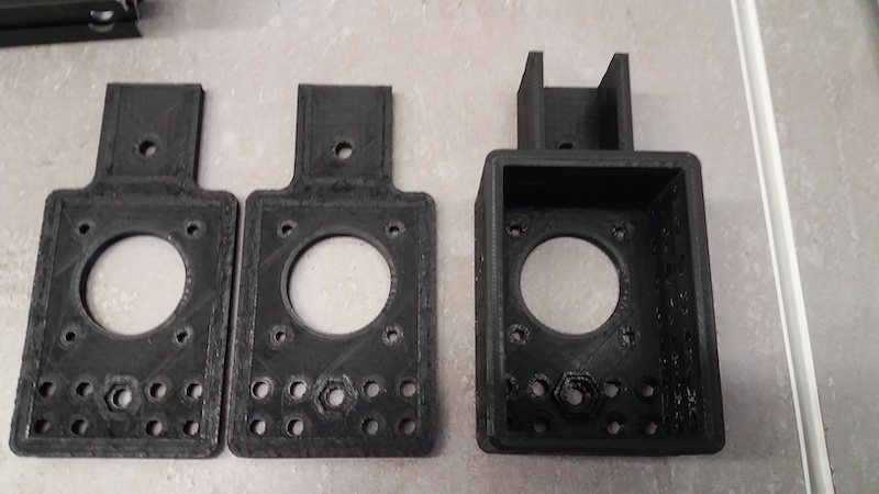
Printing the parts
We did this week very collaboratively and many tasks were not clearly made by one person, but by the group.
For the frame of our CNC, we decided to use the printable parts made by Quentin Bolsée. We didn’t modify the parts for the frame and for holding the stepper motors. We had some failures when printings these parts, because I set the infill to 100%. Rudolf told me that a lower infill would be better, so we set it to 42% and it printed smoothly.
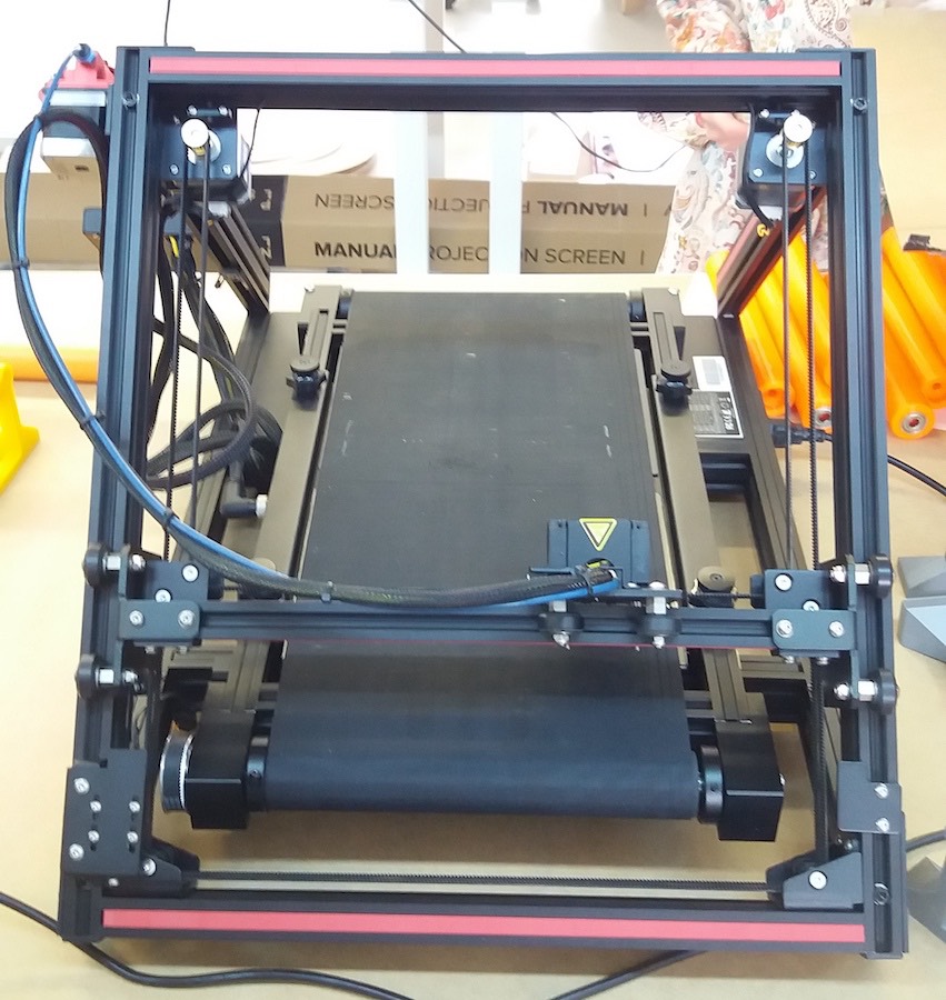
To print longer axes, we will use the Creality CR30, which can print theoretically an infinite length in one of the dimensions. Babken ordered it some months ago and we were lucky to receive it during this week. Our first task was then to assemble this machine.
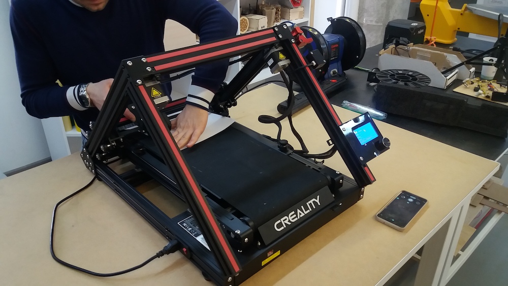
This printer has the same mechanism as the CNC we want to build: it’s a CoreXY
The setup wasn’t as easy as we thought. It took many trials and errors to achieve a satisfactory zeroing:
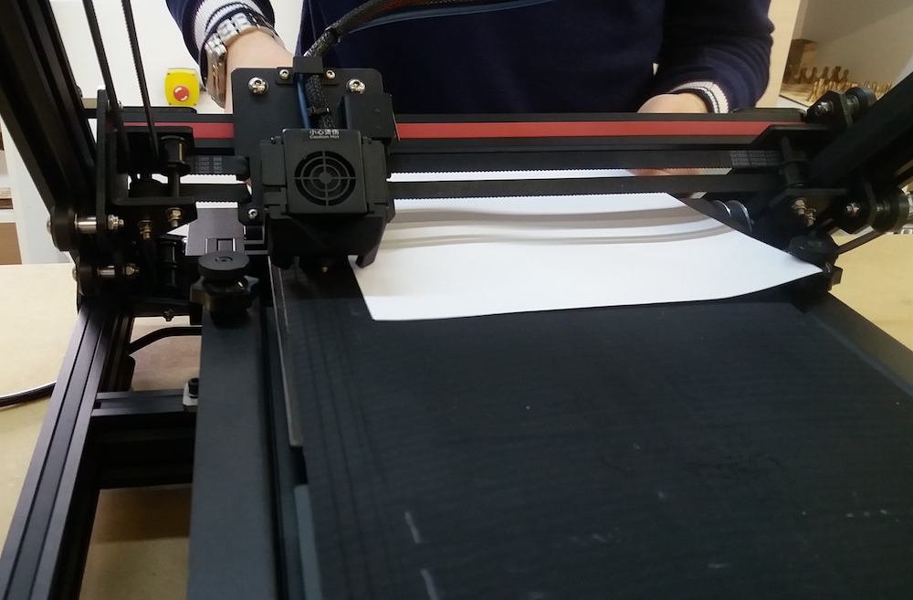
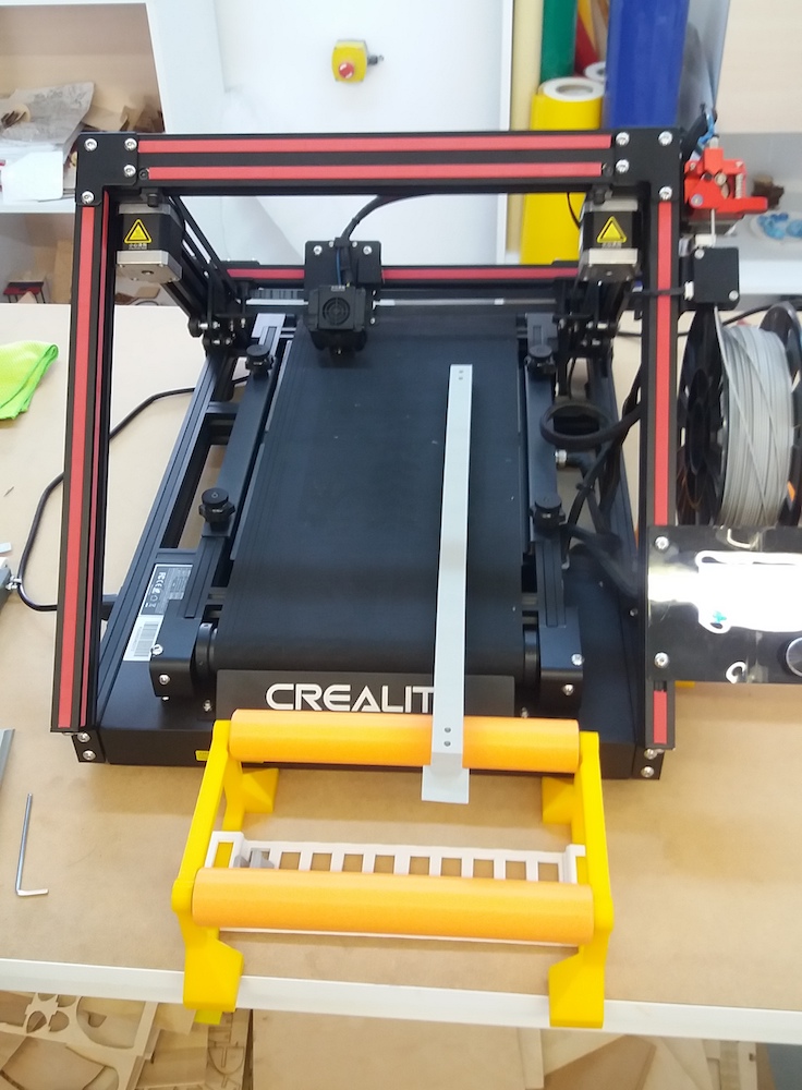
It was very useful for printing the movable axis of our CNC since it was too long for any of our other 3D printers:
Using the Arduino CNC shield
For this task, I followed mostly this tutorial on how to use stepper motors and arduino, this one which addresses specifically grbl and this youtube video.
I tried the CNC shield with the NEMA17 motors and A4988 drivers.
In order to use the the CoreXY mechanism in grbl, I first had to modify a file in Arduino -> libraries -> grbl -> config.h. It was quite simple, since I just had to uncomment one line:
...

// Enable CoreXY kinematics. Use ONLY with CoreXY machines.
// IMPORTANT: If homing is enabled, you must reconfigure the homing cycle #defines above to
// #define HOMING_CYCLE_0 (1<<X_AXIS) and #define HOMING_CYCLE_1 (1<<Y_AXIS)
// NOTE: This configuration option alters the motion of the X and Y axes to principle of operation
// defined at (http://corexy.com/theory.html). Motors are assumed to positioned and wired exactly as
// described, if not, motions may move in strange directions. Grbl requires the CoreXY A and B motors
// have the same steps per mm internally.
#define COREXY // Default disabled. Uncomment to enable.
Assembling the CNC
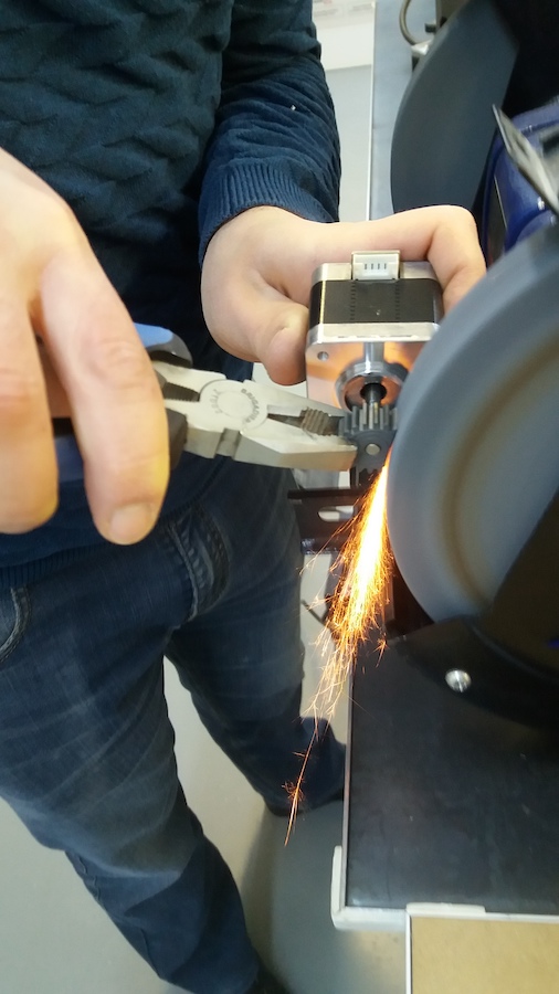
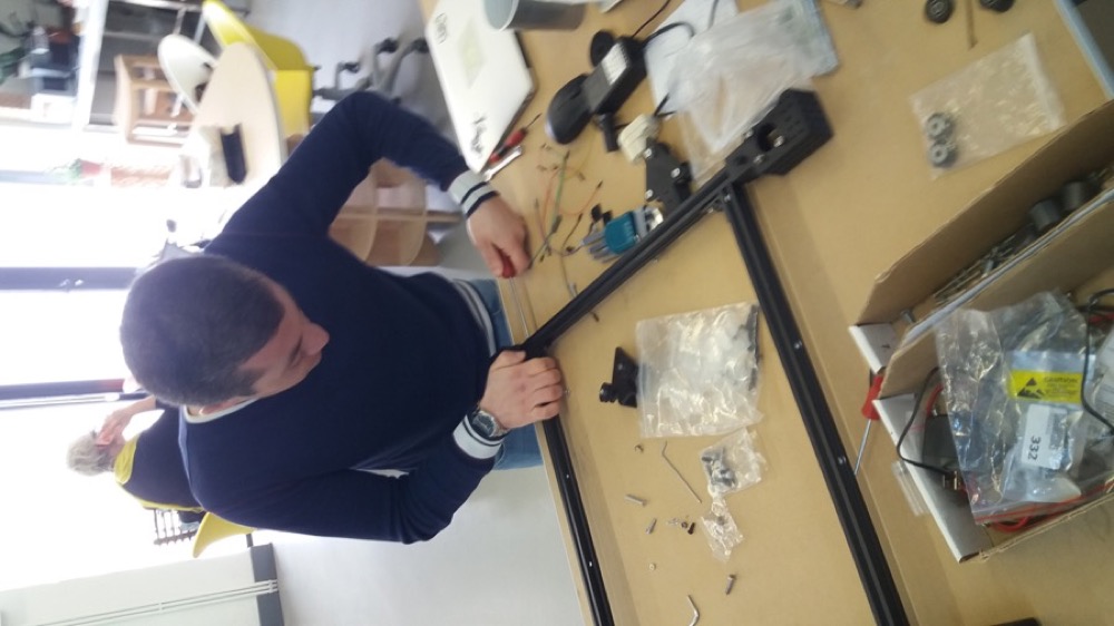
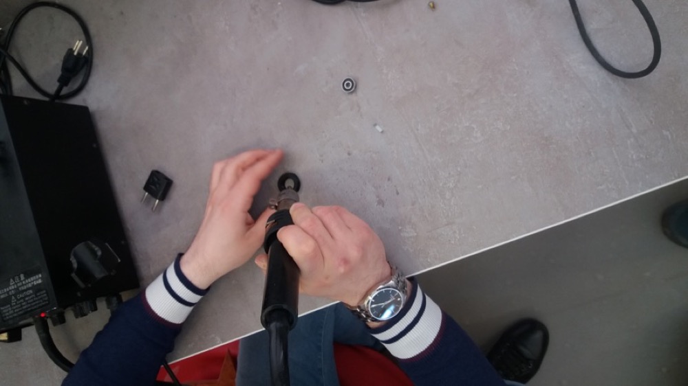
Since we wanted to use the stepper motors we scavenged from the disassembled printer, we first had to remove the gear from the shaft.
Rudolf did a great job with it.
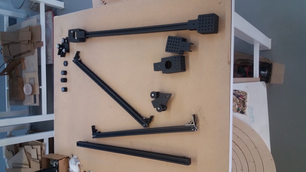
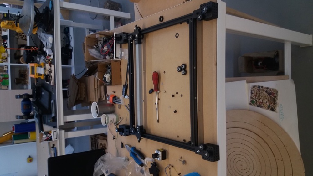
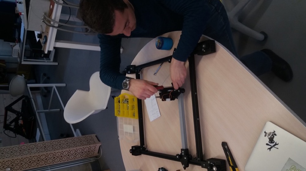
Once we had printed and gathered most of the parts needed, we could start assembling our machine.
The aluminium profiles used to belong to a 3D printer and some holes were already made. We used the holes available, but we had to make our own thread:

We could then screw our aluminium profiles perpendicular to each other:
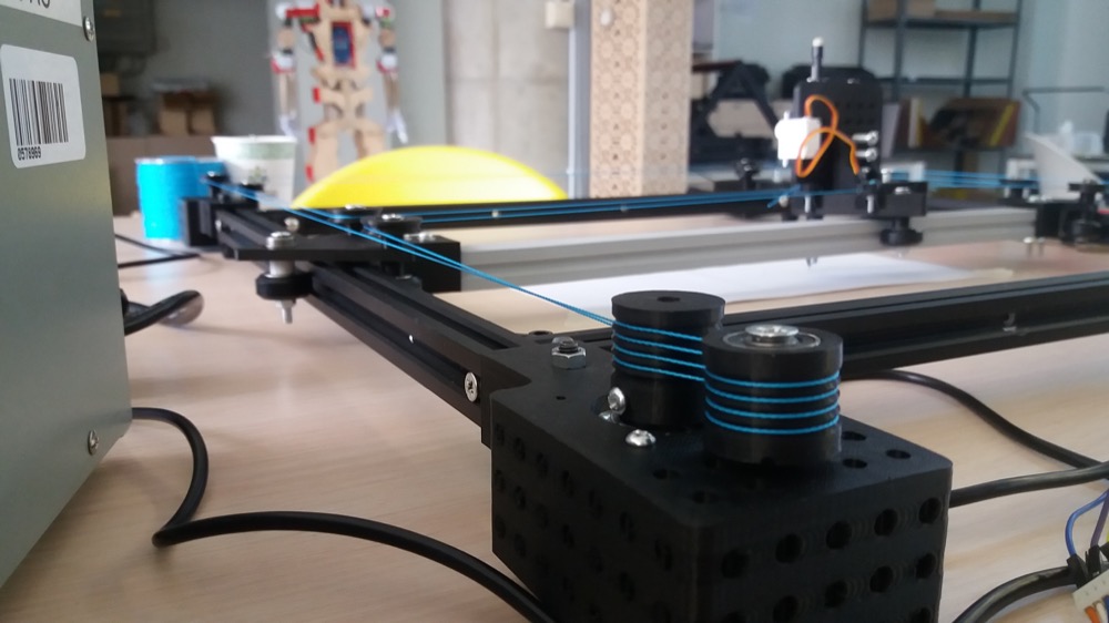
We printed some pulleys, and we had to insert a radial bearing in each of them. In order to do so, we blew some hot air on it to soften the plastic.
It was then easier to insert the bearing:
One of the main challenges we faced when assembling the CNC was to find the right nuts and bolts in our limited stock. The ones we recovered from the printer we disassembled came in handy.
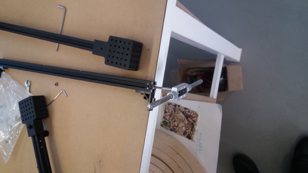
Once the main frame was assembled, we could add the pen holder:
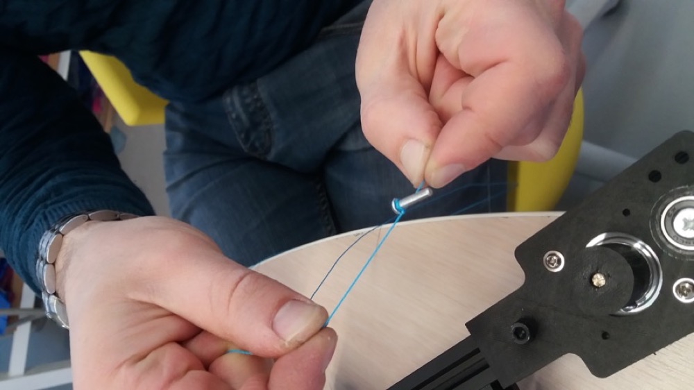
Eventually, we could install the wire:
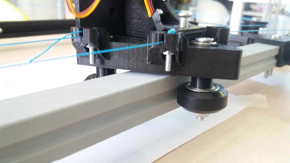
Once everything was assembled, we noticed that the 3D printed beams’ slit had a slit which was slightly too small for our wheels:
Using the CNC
The GRBL workflow is quite straight forward. We can simply follow the setup wizard.
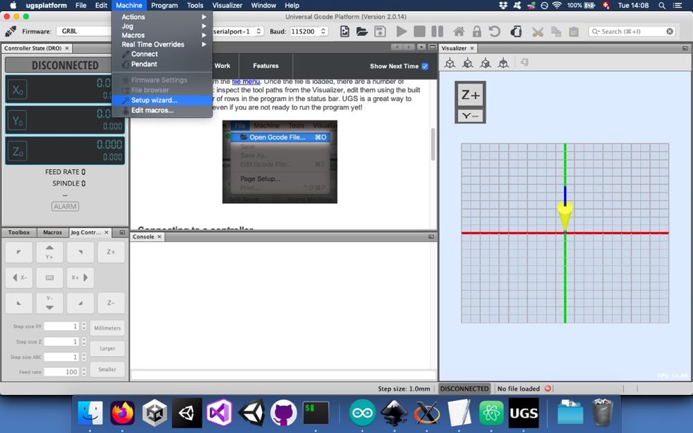
We need first to find the right port and set the baud rate.
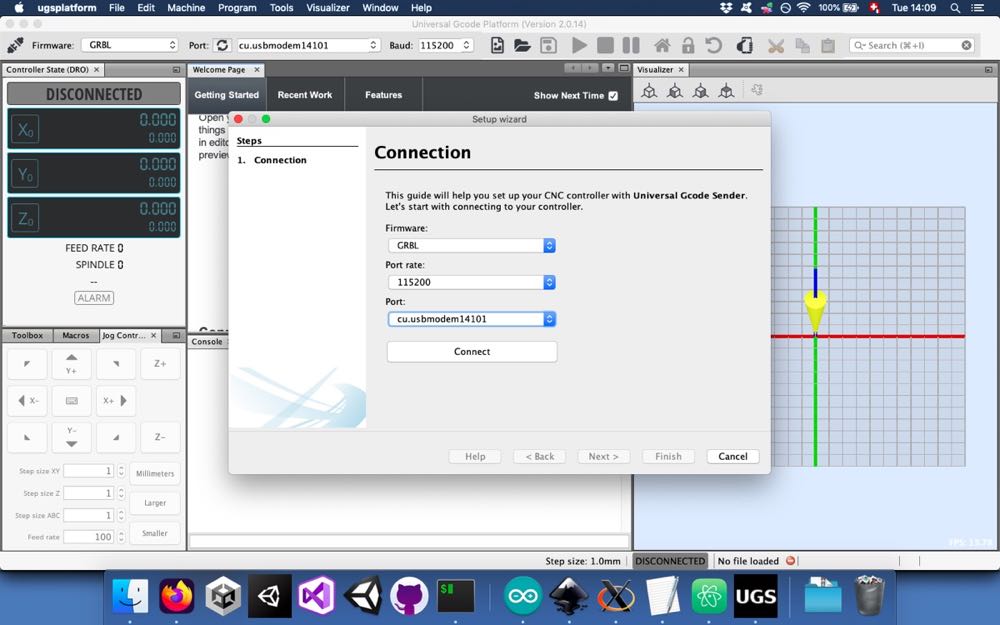
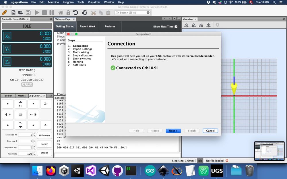
Then we wait for the connection.
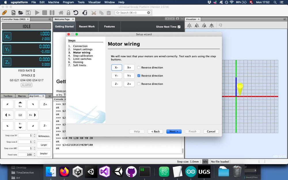
We can then test some steps in the different directions. In our case, we had to reverse the Y direction to make it work properly.
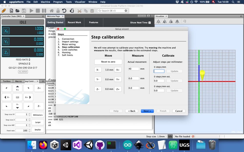
In the next screen, it is possible to adjust the number of steps per millimeter. In our case, it seemed that our motor didn’t have many steps, since we had to decrease the steps per mm quite a bit.
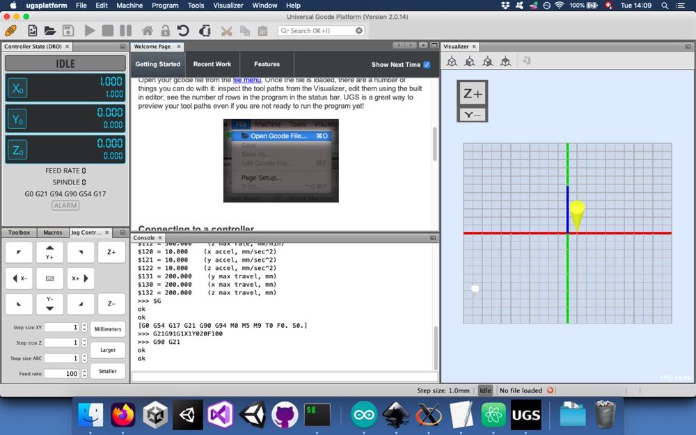
Now we are set up and we can launch our g code.
Implementing the servo
Since we wanted to use our CNC as a pen plotter, we couldn’t use the software Universal Gcode Platform as is. It is able to control a third stepper motor for the Z-axis but, we are using a servo motor. In order to overcome this obstacle, we followed these instructions.
We first had to install a modified version of GRBL on the Arduino. We remved all
the files in the ~/Arduino/libraries/grbl folder and pasted the corresponding
files downloaded here.
We then wired the servo motor to the CNC Shield:
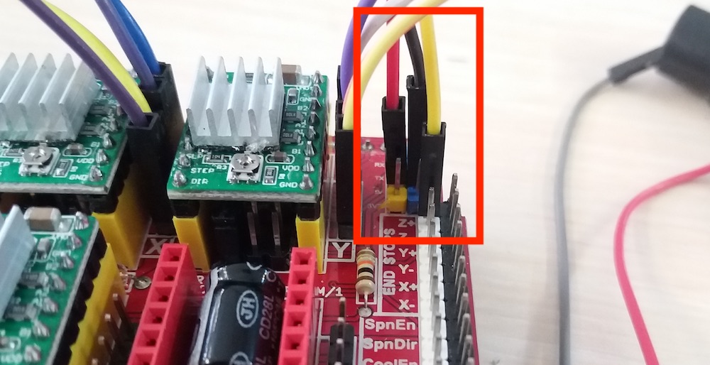
We plugged the ground and the +5V wires to the corresponding pins on the shield. For the signal wire, we used the Z+ pin of the shield, since we wouldn’t use it anyway. This pin would be used if we would have Z-axis stop switch.
In order to produce the appropriate g-code, we had to install an extension to Inkscape. We downloaded the appropriate files here and copied them in the appropriate directory. Since we were using MacOS, it was:
~/.config/inkscape/extensions
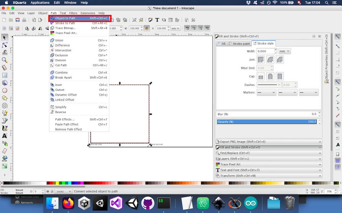
For testing purposes, we drew a simple square of 10cm and converted it to path:
To create the appropriate g-code, we used the extension that we just installed:
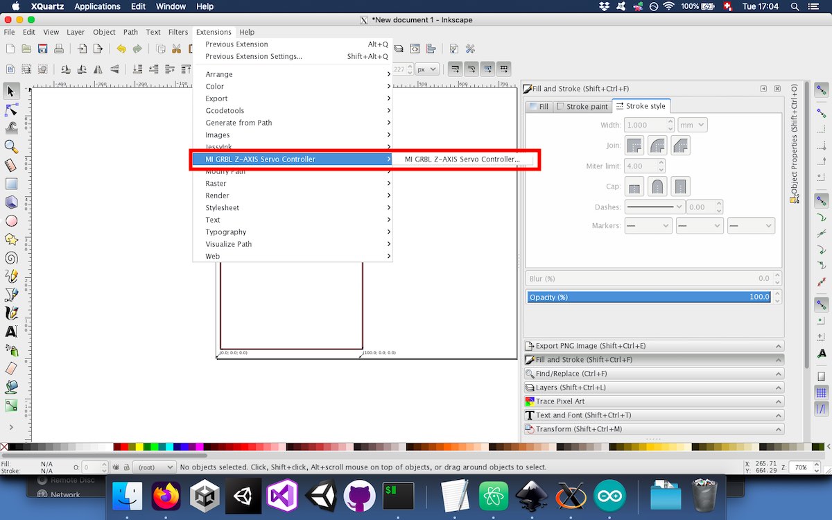
There are few options available when creating the g-code:
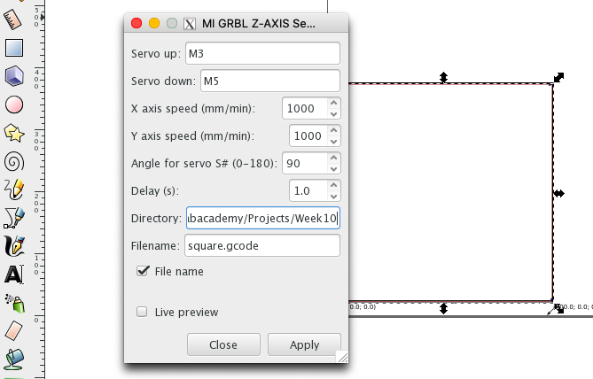
Here, we use M3 and M5, which are normally used to turn on and off the spindle, to pilot the servo motor.
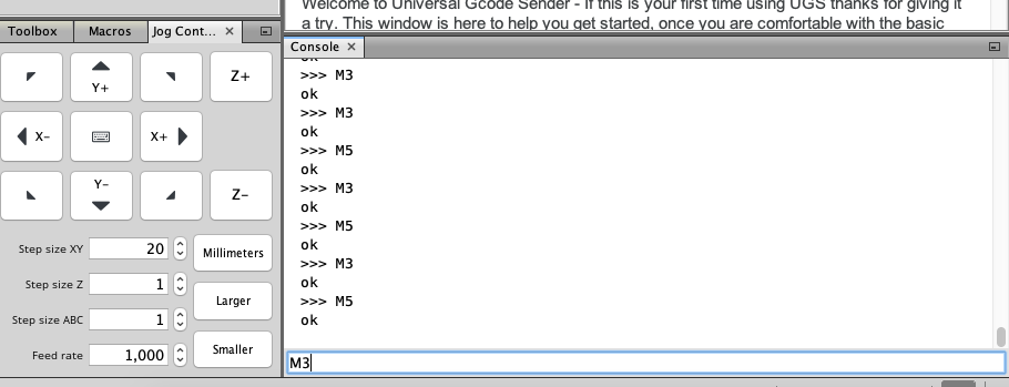
To test the servo, we could use the M3 and M5 commands in Universal Gcode Platform (UGS):
We then tried to feed UGS with some custom g code with an implementation for the servo motor without the lowering and lifting mechanism.
In order to modify the range of the servo’s movement, we modified the code like this:
...

#include "grbl.h"

#define RC_SERVO_SHORT     15       // Timer ticks for 0.6ms pulse duration  (9 for 0.6ms)
#define RC_SERVO_LONG      20       // Timer ticks for 2.5 ms pulse duration  (39 for 2.5ms)  (it was 32 before modification)
//#define RC_SERVO_INVERT     1     // Uncomment to invert servo direction

...
Addressing the slow movement
We had an issue with the movement of our CNC being correct but extremely slow. In order to mitigate this, the main variable we found was the ACCELERATION_TICKS_PER_SECOND. we decreased it significantly and the movement was less slow.
...

// The temporal resolution of the acceleration management subsystem. A higher number gives smoother
// acceleration, particularly noticeable on machines that run at very high feedrates, but may negatively
// impact performance. The correct value for this parameter is machine dependent, so it's advised to
// set this only as high as needed. Approximate successful values can widely range from 50 to 200 or more.
// NOTE: Changing this value also changes the execution time of a segment in the step segment buffer.
// When increasing this value, this stores less overall time in the segment buffer and vice versa. Make
// certain the step segment buffer is increased/decreased to account for these changes.
#define ACCELERATION_TICKS_PER_SECOND 50      // was 100

...
Conclusion
These two weeks making a machine together was quite fun. It was very interesting to learn about the CoreXY mechanism and to actuate our machine by hand. Once it was assembled there was quite a bit of tuning to do before it was actually working. This was a bit surprising to me but since I like solving this kind of problems, it was fun for me.