Machine Building Group Site
Project name
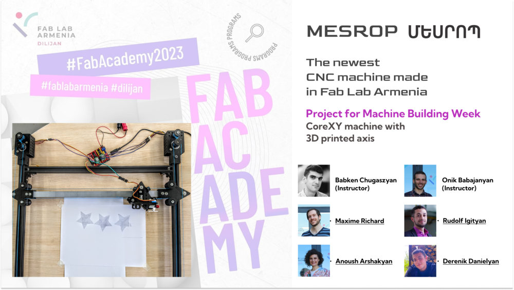
Մեսրոպ Mesrop
It’s named after Mesrop Mashtots. He is best known for inventing the Armenian alphabet c. 405 AD, and translating the Bible to Armenian.
Slide and Video
Just in case
Members
…
Students Maxime Richard, Rudolf Igityan, Anoush Arshakyan, Derenik Danielyan
Instructors Babken Chugaszyan, Onik Babajanyan
Story
- This machine is based on Beehive design by Quentin Bolsée which is one of many iterations of Urumbu design.
BOM
Files
3D print parts
481mm-long-rail.stl
main triangle.stl
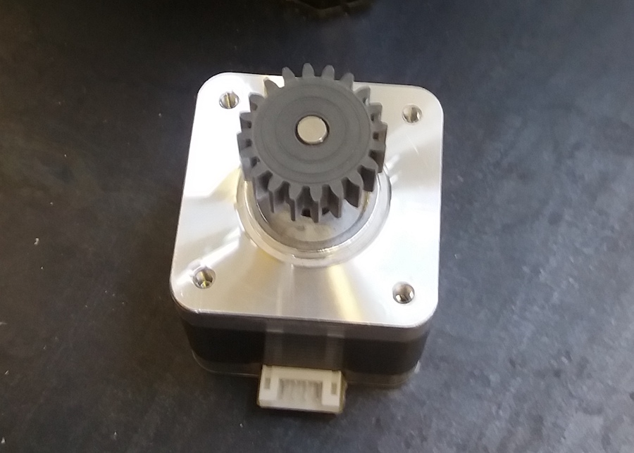
capstan_motor.stl
capstan_pulley.stl
pulley.stl
Spacer002 (Meshed).stl
Machine Dismantling
Creative destruction or how it all began.
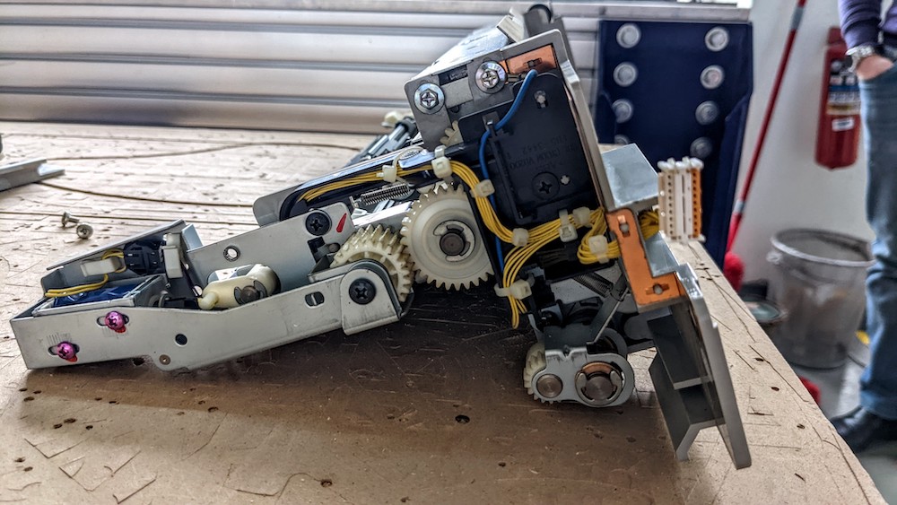
Our machine building process started with machine dissasembling (Canon printing station).
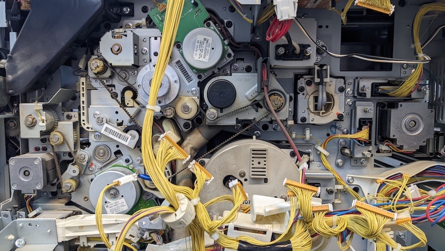
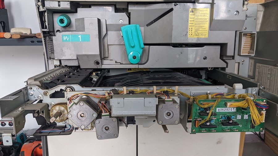
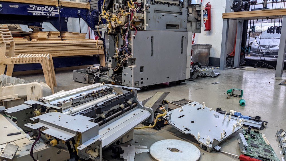 During the process of disassembling, we stumbled upon a trove of mechanical and electrical parts that we could have only dreamed of. Stepper motors, DC motors, cooling fans, bearings, solenoids, sensors,and countless wires - this intricate web was truly magical. These seemingly insignificant parts, which may have been destined for the trash heap, will find new life and purpose in the innovative machines created at the Fab Lab.
 Upcycling not only reduces electronic waste, but also saves energy and resources by minimizing the need to produce new components from scratch. Additionally, upcycling promotes a culture of repair and maintenance, encouraging people to value and extend the lifespan of their possessions. While upcycling may require more effort and expertise than simply buying new components, the benefits to the environment and economy make it a worthwhile pursuit. Furthermore, as technology advances and becomes more complex, upcycling can provide a valuable source of materials for future innovations.
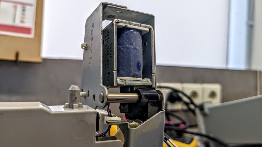
 Among the many “treasures” we found a solenoid, one of them was connected to the DC power supply. Look how beautiful it works!
Switches
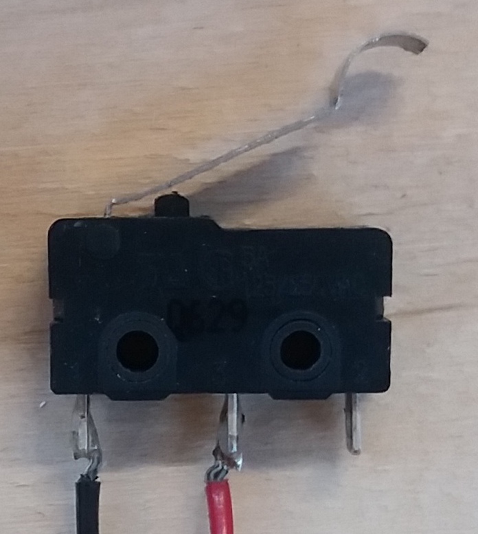
In the printer, we found some mechanical switches, which trigger when the metallic part is pushed:
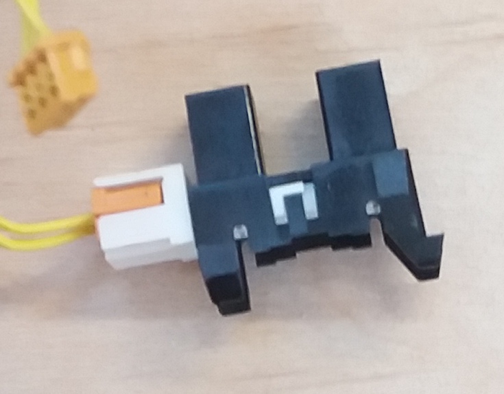
and also some optical switches:
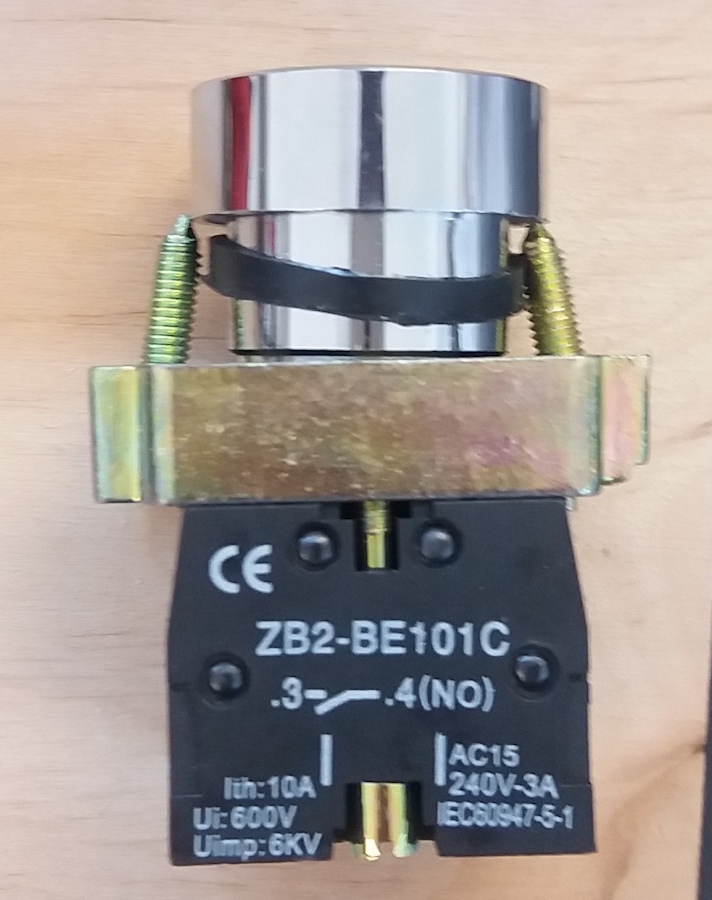
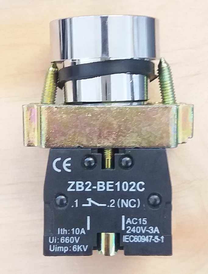
Buttons
We learnt about Normally Open (NO) and Normally Closed (NC) mechanism in buttons. The default state of the NO button is an open circuit, where no current is flowing, and in an NC button, the default state is a closed circuit, where the current can flow. Some buttons have the possibility to choose which default state we want:
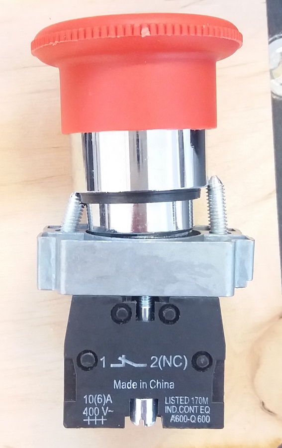
For safety button, the default state should always be closed, so that the button triggers in case of failure of its circuit:
Bearings
- radial bearing: designed to sustain forces applied perpendicular to the axis of rotation

- thrust bearing: designed to sustain forces applied parallel to the axis of rotation
- friction bearing: no balls, just lubricant
- tapered roller bearing: designed to sustain forces applied perpendicular to the axis of rotation, as well as one direction parallel to this axis.
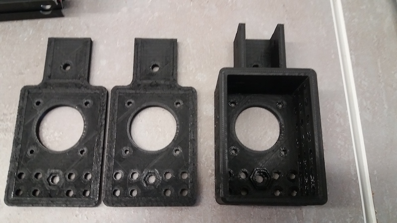
Printing the parts
For the frame of our CNC, we decided to use the printable parts made by Quentin Bolsée. We didn’t modify the parts for the frame and for holding the stepper motors.
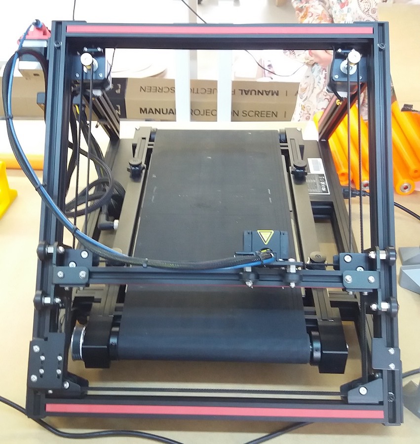
During this week we were lucky to recieve the CR30 printer that was ordered 5 months ago. We assembled it and were able to print one of the axis.
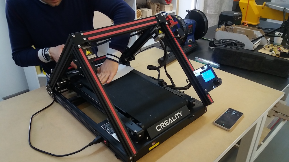
This printer has the same mechanism as the CNC we want to build: it’s a CoreXY
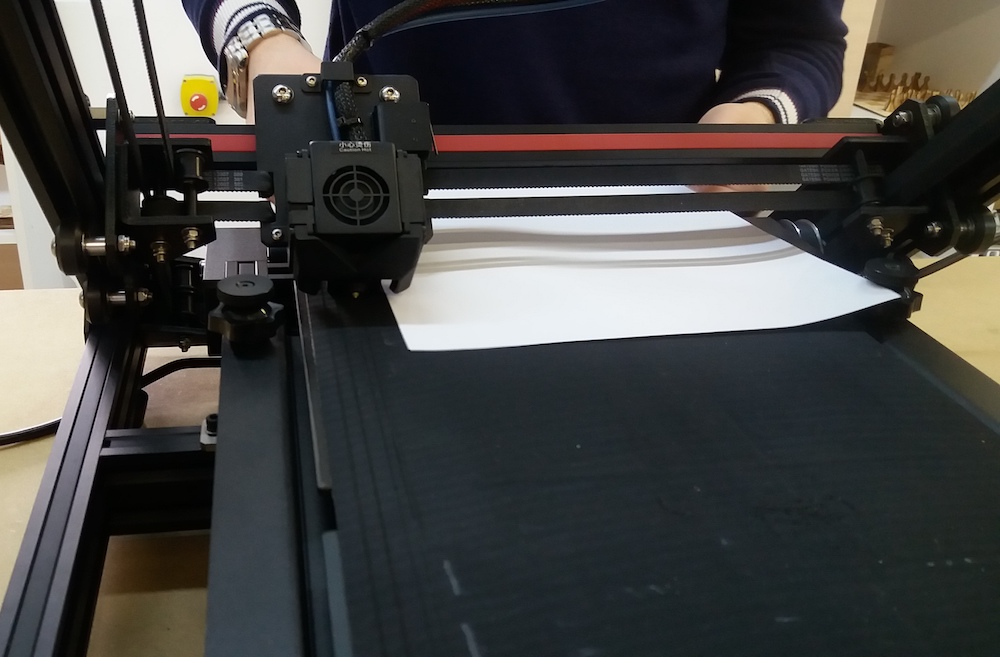
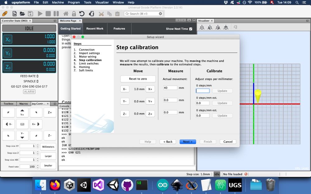
The setup wasn’t as easy as we thought. It took many trials and errors to achieve a satisfactory zeroing:
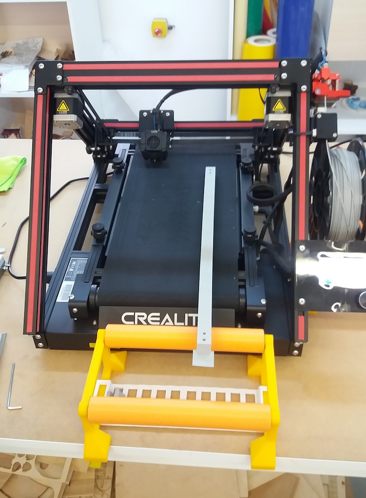
It was very useful for printing the movable axis of our CNC since it was too long for any of our other 3D printers:
Using the Arduino CNC shield
https://howtomechatronics.com/tutorials/arduino/stepper-motors-and-arduino-the-ultimate-guide/ https://howtomechatronics.com/tutorials/how-to-setup-grbl-control-cnc-machine-with-arduino/
in Arduino -> libraries -> grbl -> config.h
...

// Enable CoreXY kinematics. Use ONLY with CoreXY machines.
// IMPORTANT: If homing is enabled, you must reconfigure the homing cycle #defines above to
// #define HOMING_CYCLE_0 (1<<X_AXIS) and #define HOMING_CYCLE_1 (1<<Y_AXIS)
// NOTE: This configuration option alters the motion of the X and Y axes to principle of operation
// defined at (http://corexy.com/theory.html). Motors are assumed to positioned and wired exactly as
// described, if not, motions may move in strange directions. Grbl requires the CoreXY A and B motors
// have the same steps per mm internally.
#define COREXY // Default disabled. Uncomment to enable.
https://www.youtube.com/watch?v=zUb8tiFCwmk

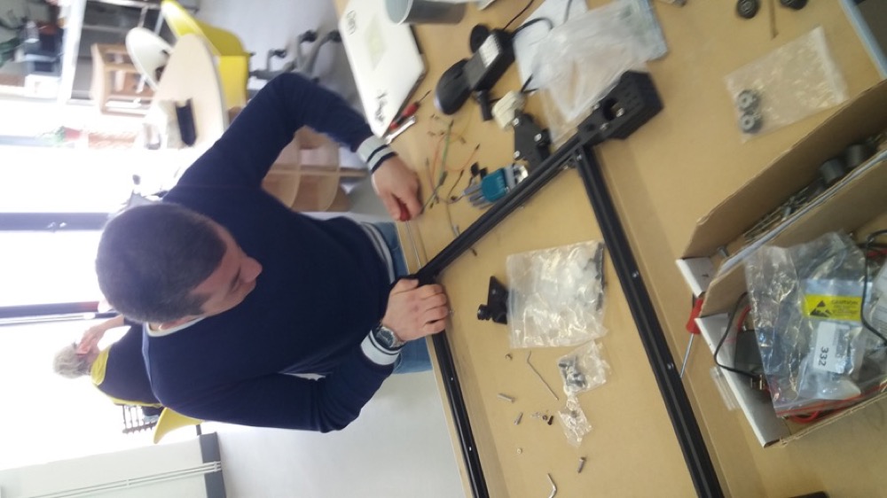
Assembling the CNC
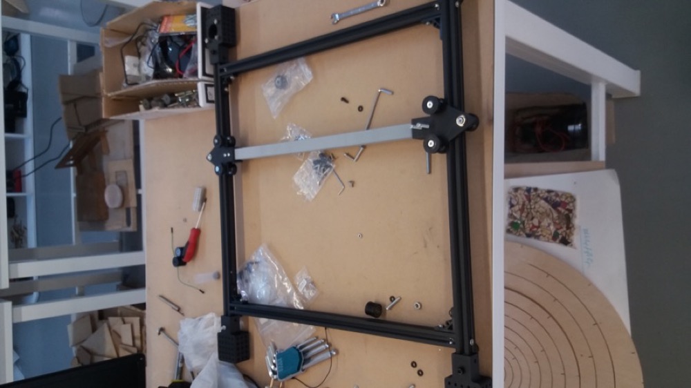
Once we had printed and gathered most of the parts needed, we could start assembling our machine.
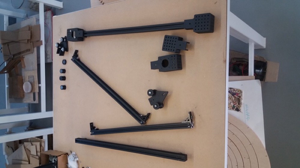
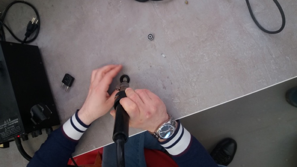
The aluminium profiles used to belong to a 3D printer and some holes were already made. We used the holes available, but we had to make our own thread:
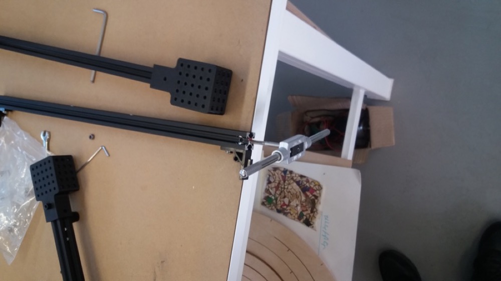

We could then screw our aluminium profiles perpendicular to each other:
We printed some pulleys, and we had to insert a radial bearing in each of them. In order to do so, we blew some hot air on it to soften the plastic.
It was then easier to insert the bearing:

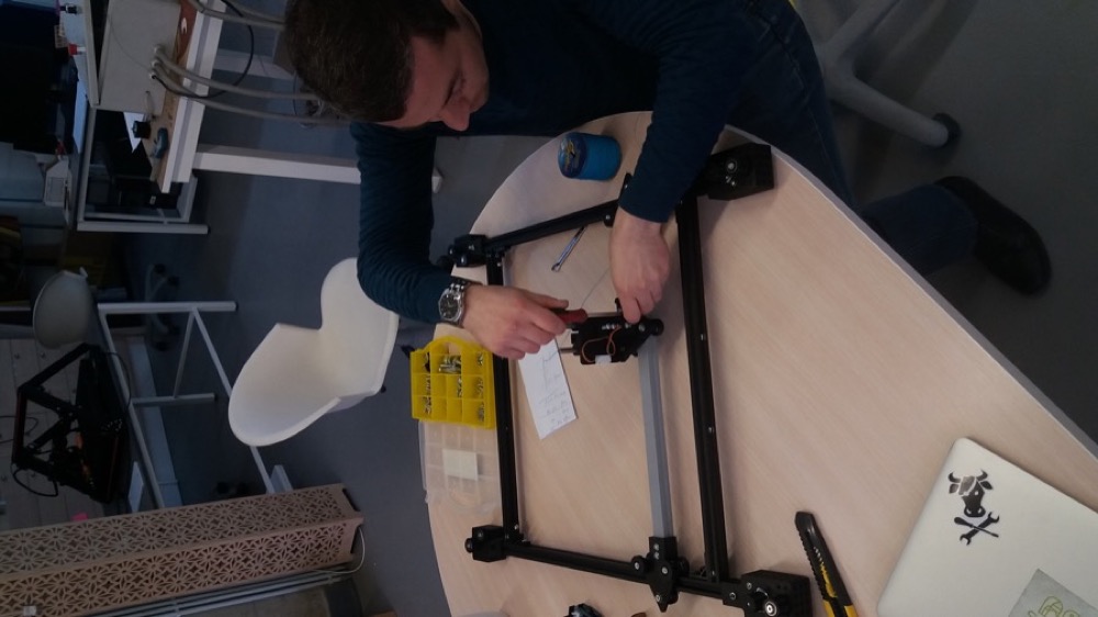
One of the main challenges we faced when assmbling the CNC was to find the right nuts and bolts in our limited stock. The ones we recovered from the printer we disassembled came in handy.
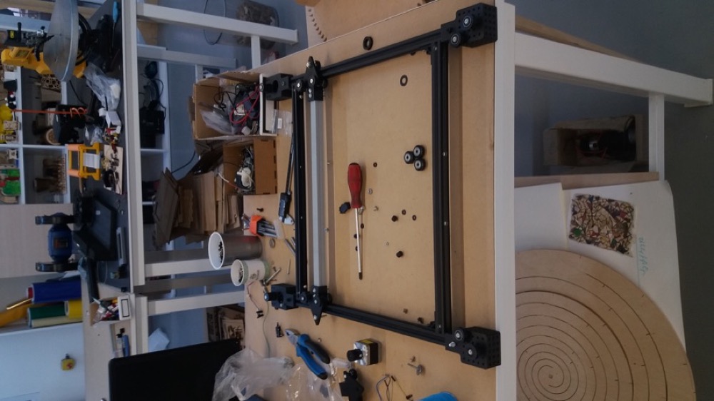
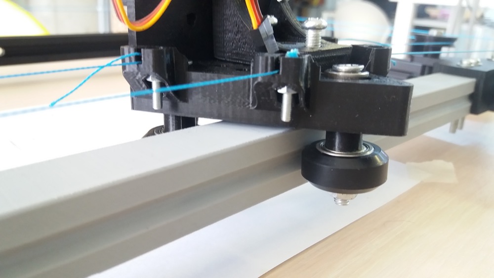
Once the main frame was assembled, we could add the pen holder:
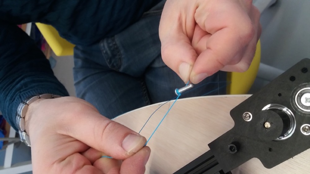
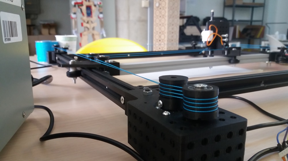
Eventually, we could install the wire:
Once everything was assembled, we noticed that the 3D printed beams’ slit had a slit which was slightly too small for our wheels:
Using the CNC


Implementing the servo
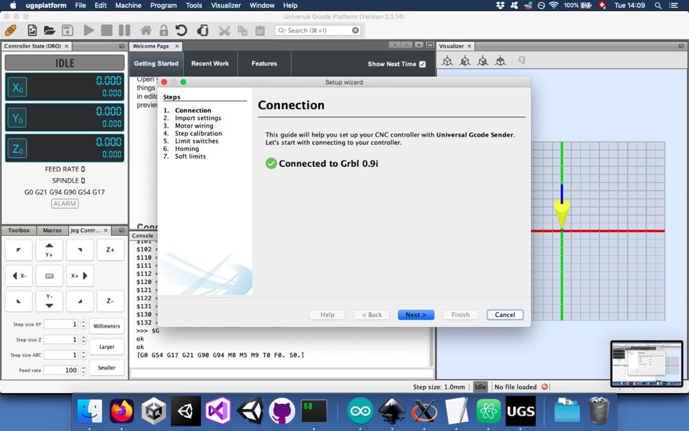
Since we wanted to use our CNC as a pen plotter, we couldn’t use the software Universal Gcode Platform as is. It is able to control a third stepper motor for the Z-axis but, we are using a servo motor. In order to overcome this obstacle, we followed these instructions.
We first had to install a modified version of GRBL on the Arduino. We remved all
the files in the ~/Arduino/libraries/grbl folder and pasted the corresponding
files downloaded here.
We then wired the servo motor to the CNC Shield:
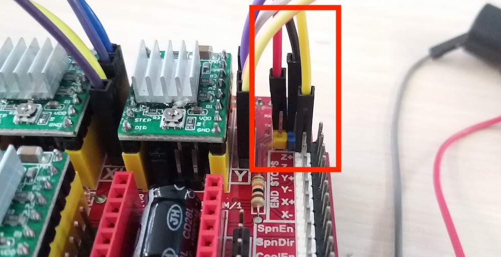
We plugged the ground and the +5V wires to the corresponding pins on the shield. For the signal wire, we used the Z+ pin of the shield, since we wouldn’t use it anyway. This pin would be used if we would have Z-axis stop switch.
In order to produce the appropriate g-code, we had to install an extension to Inkscape. We downloaded the appropriate files here and copied them in the appropriate directory. Since we were using MacOS, it was:
~/.config/inkscape/extensions
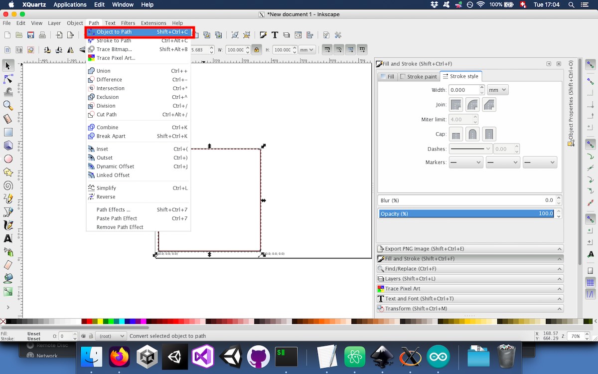
For testing purposes, we drew a simple square of 10cm and converted it to path:
To create the appropriate g-code, we used the extension that we just installed:
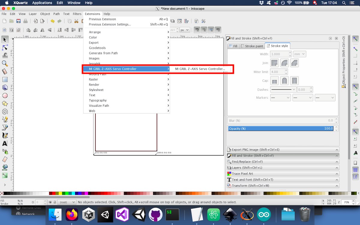
There are few options available when creating the g-code:
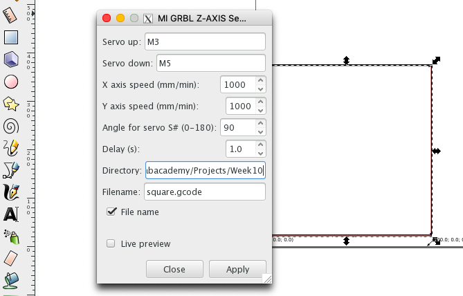
Here, we use M3 and M5, which are normally used to turn on and off the spindle, to pilot the servo motor.
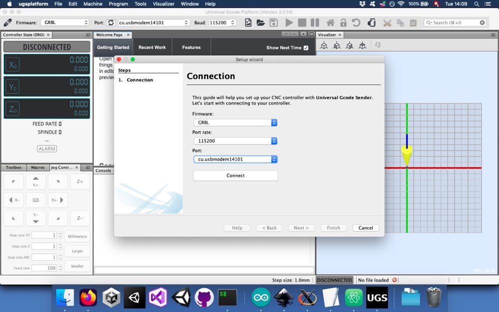
To test the servo, we could use the M3 and M5 commands in Universal Gcode Platform (UGS):
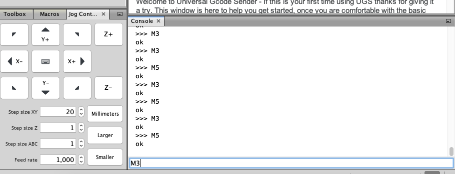
We then tested to feed UGS with some custom g code with an implementation for the servo motor without the lowering and lifting mechanism: