5. 3D Scanning and printing
Group assignment
Differences in working with MakerBot Replicator 2 and Creality Ender-3 v1 3D printers
Table characteristics
-
MakerBot Replicator 2, the platform on which the part is printed is made of acrylic, paper scotch is attached to its upper side so that it can be replaced. The platform can be easily removed. The filament adheres rigidly to the surface of the table. Sometimes, to tear off from the table, you have to use a knife or a spatula. This table is not heated.
-
The Ender-3 has a static desk platform made of aluminum with a special coating on it. The platform is not removable. The platform is endowed with a heating function. The disadvantage of such a table is that if the ratio of the height of the printed model to the area of the lower part of the model is large, then it needs raft or brim to increase the adhesion area to the table surface, otherwise it is likely that the part will come off the table surface during printing. Which in turn increases the number material used.
Types of material used
-
MakerBot works with PLA
-
Ender-3 with both PLA and ABS (not recommended for indoor use, good ventilation is needed)
3D printer extruder nozzle
-
MakerBot has a static 0.4 mm extruder nozzle, not designed for frequent replacements
-
And the Ender-3 has a frequently replaced extruder nozzle, which allows you to put different sized nozzles which in turn enables to print more accurately, by increasing the printing time or less accurately but fast.
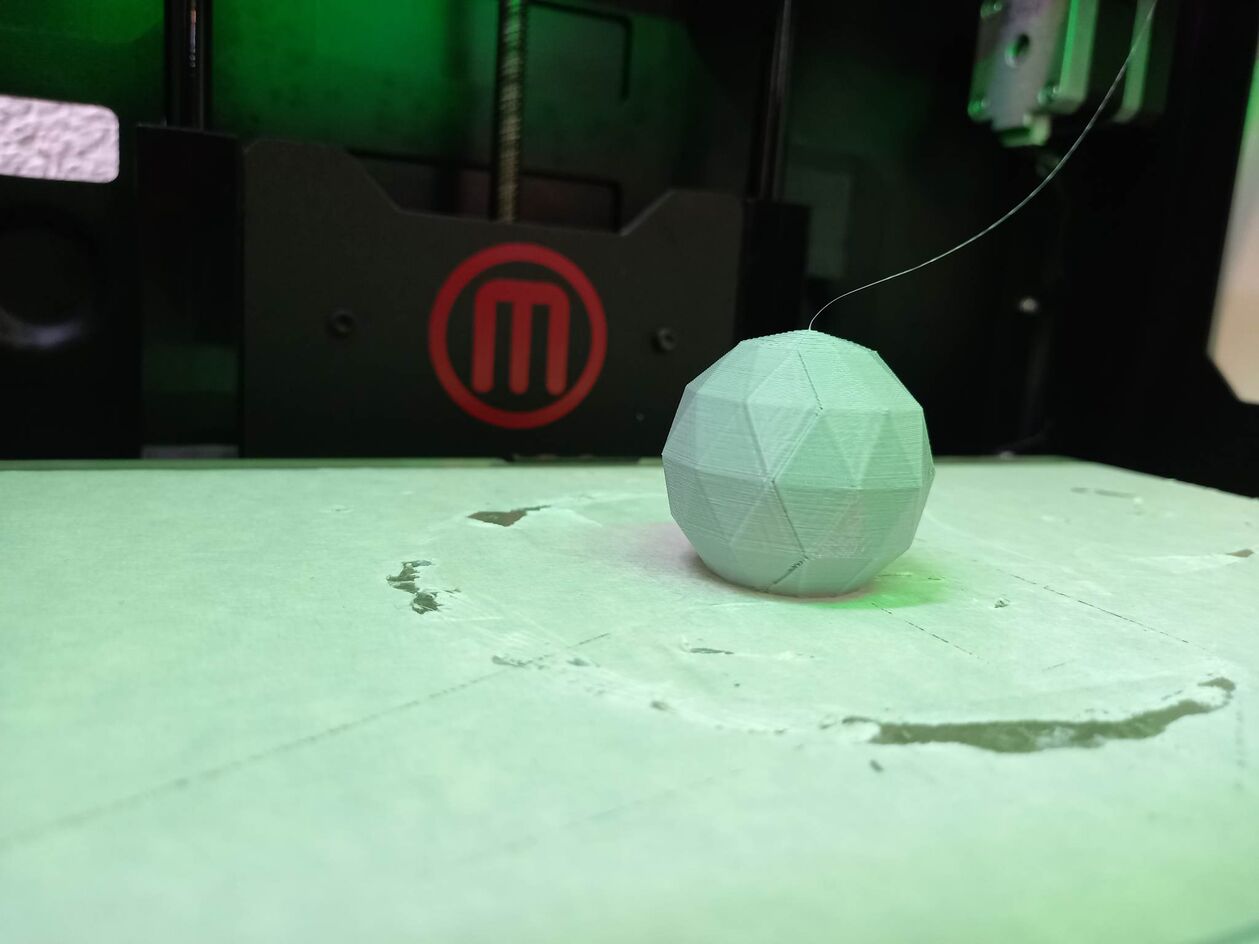
Print detail depending on Meshing options
In order to generate the (G code), we need to export the model we created in STL format. But before that, you need to modify the model to Meshing Design. Meshing Design represents our model assembled from triangles. And the smaller the size of the triangles, the cleaner our model will be printed.
As part of the group work, we decided to design a sphere with a radius of 18mm cutted from the bottom. We cut the sphere from the bottom by 6mm.
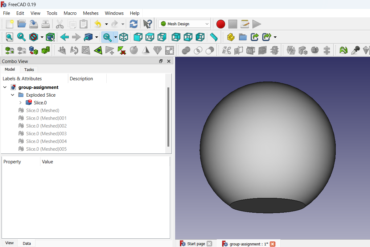
Meshing options
In order to get STL file we need to create a mesh from a solid. Freecad has nice meshing options we wanted to experiment with and create a guide. In order to create a mesh one has to go to Mesh Design workbench.
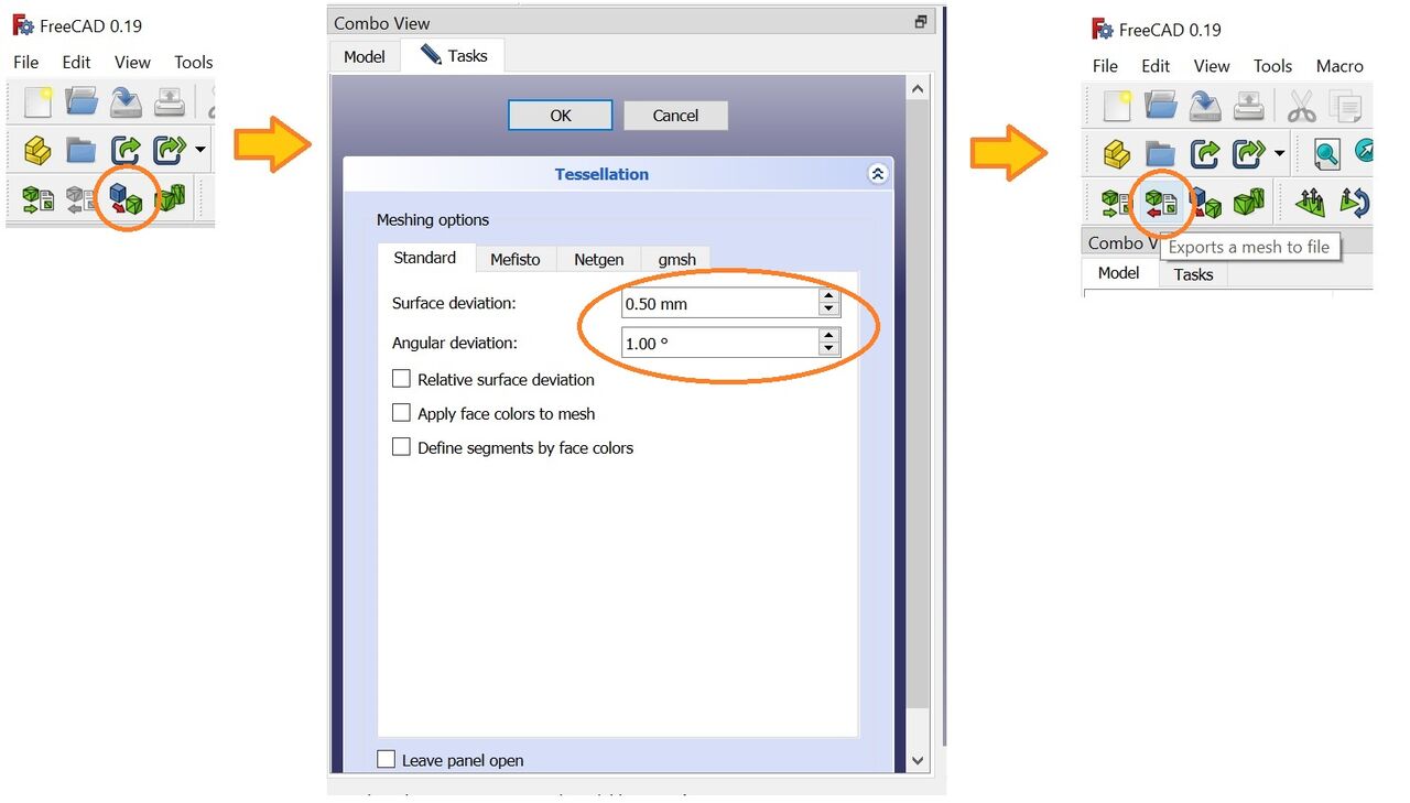
By changing the two settings Surface deviation and Angular deviation we produced 6 different meshes and printed them.
| Model 1 | Model 2 | Model 3 | Model 4 | Model 5 | Model 6 | |
|---|---|---|---|---|---|---|
| Surface deviations | 50.0 mm | 30.0 mm | 10.0 mm | 5.0 mm | 1.0 mm | 0.1 mm |
| Angular deviations | 50.0° | 30.0° | 10.0° | 5.0° | 1.0° | 1.0° |
| STL file size | 5.84 KB | 13.1 KB | 49.7 KB | 428 KB | 10 591 KB | 10 600 KB |
Geometric characteristics
| Model 1 | Model 2 | Model 3 | Model 4 | Model 5 | Model 6 | |
|---|---|---|---|---|---|---|
| Number of Point | 61 | 136 | 511 | 4 388 | 108450 | 108544 |
| Number of Edge | 177 | 402 | 1 527 | 13 158 | 325 344 | 325 626 |
| Number of Face | 118 | 268 | 1 018 | 8 772 | 216 896 | 217 084 |
Model weight, print time and file size
| Model 1 | Model 2 | Model 3 | Model 4 | Model 5 | Model 6 | |
|---|---|---|---|---|---|---|
| Weight | 6.32 g. | 6.75 g. | 6.92 g. | 6.93 g. | 6.94 g. | 6.94 g. |
| Print time | 27 min | 28 min | 29 min | 29 min | 29 min | 29 min |
| File size | 5.84kb | 13.1kb | 49.7kb | 418kb | 10.3Mb | 10.3MBb |
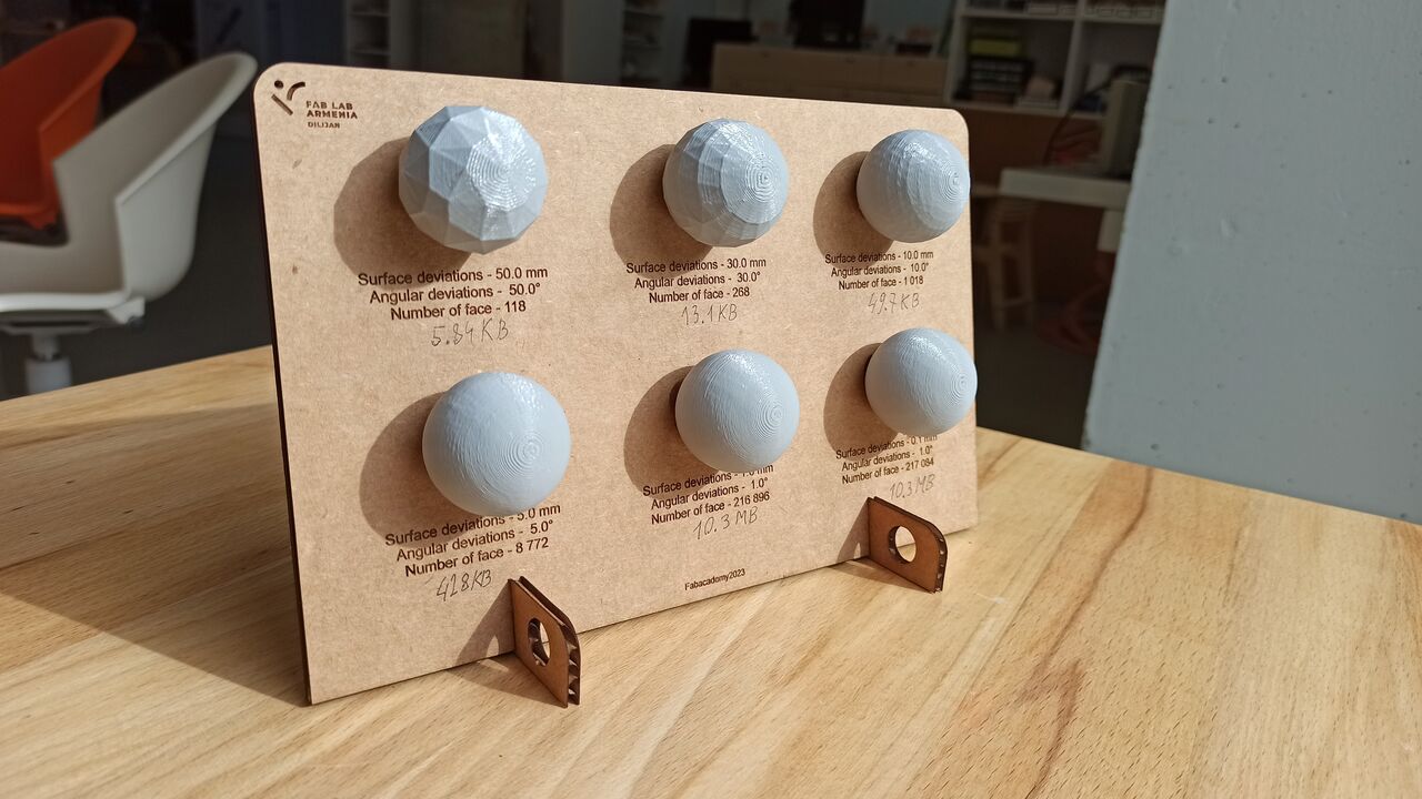
After we got the prints we lasercutted a board with the settings and results. Unfortunaltely we forgot to put file sizes so we added them later with pen.
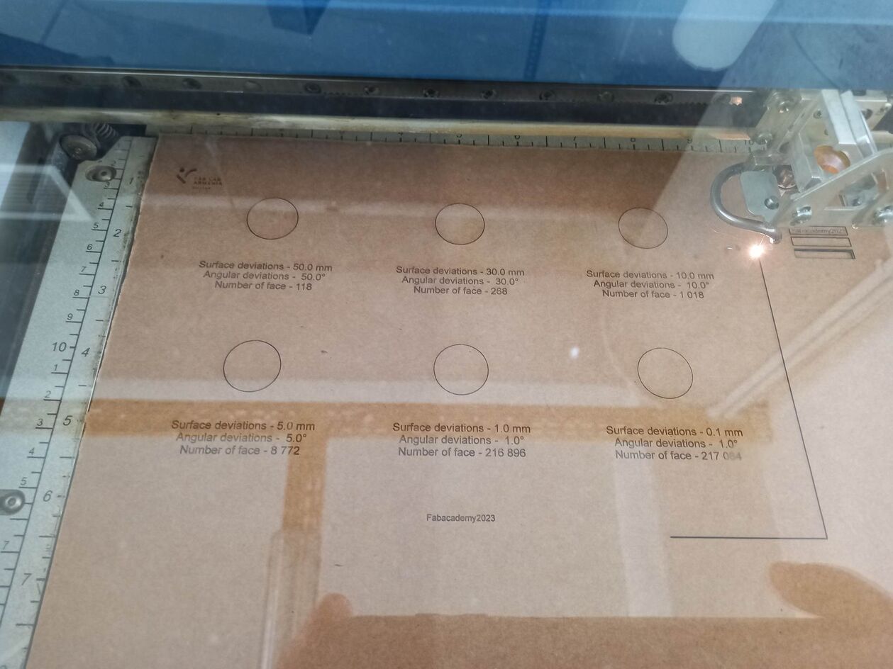
Here is the result of our work
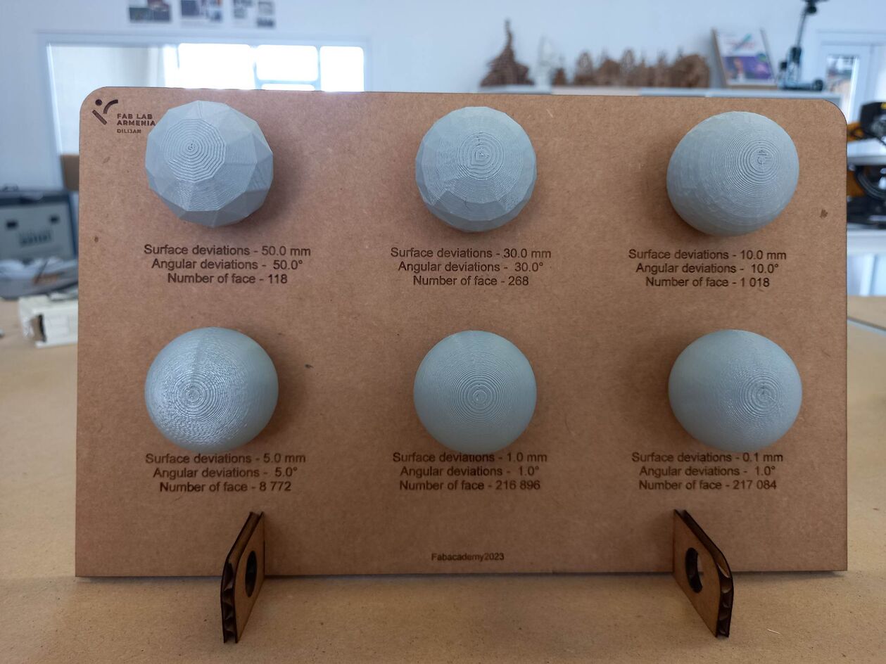
Then we added the file sizes to the lasercutted board
Here are the files:
FreeCAD file
Model 1
Model 2
Model 3
Model 4
[Model 5] and [Model 6] were more than 10MB and were almost the same so we decided not to put them here.