11. Input devices
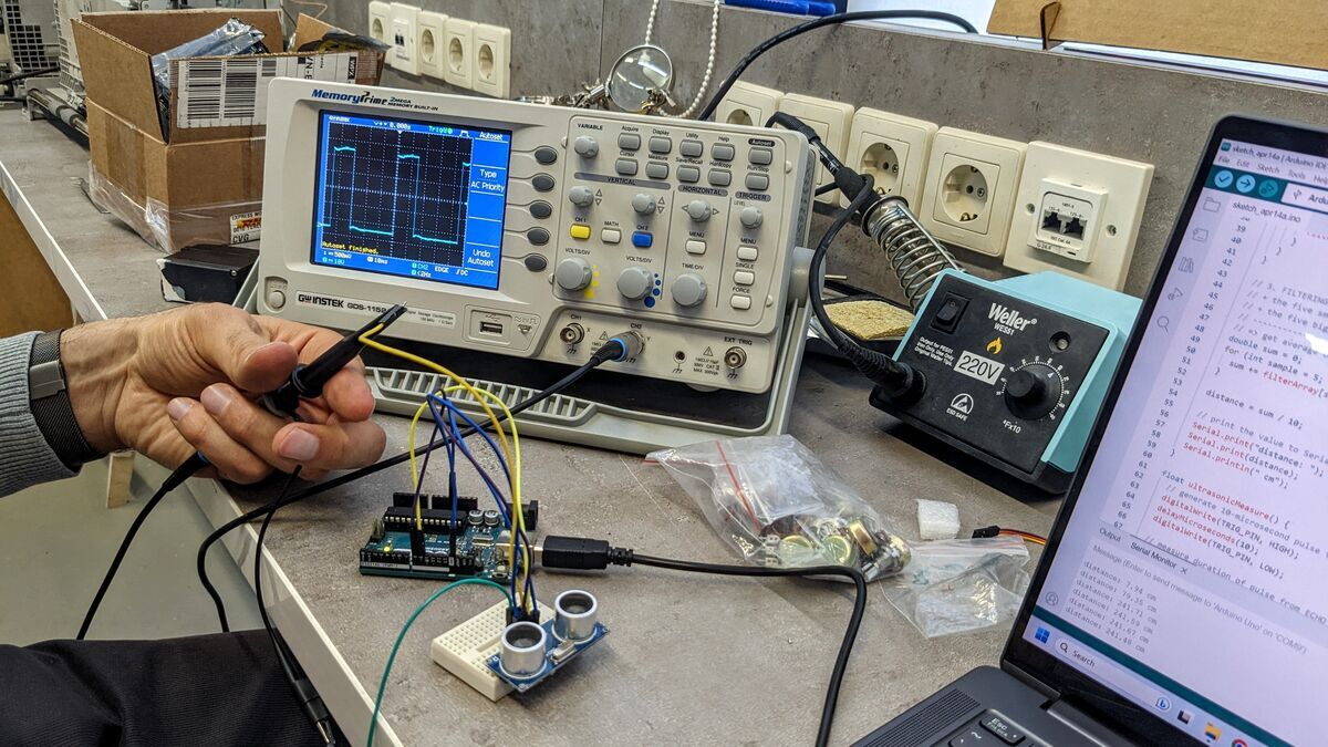
This week we tested and learned about analog and digital sensors. To visually see the values produced by the sensors, we used an oscilloscope and multimeter. And oscilloscope is an electrical device that makes it possible to see electrical vibrations with the eye.
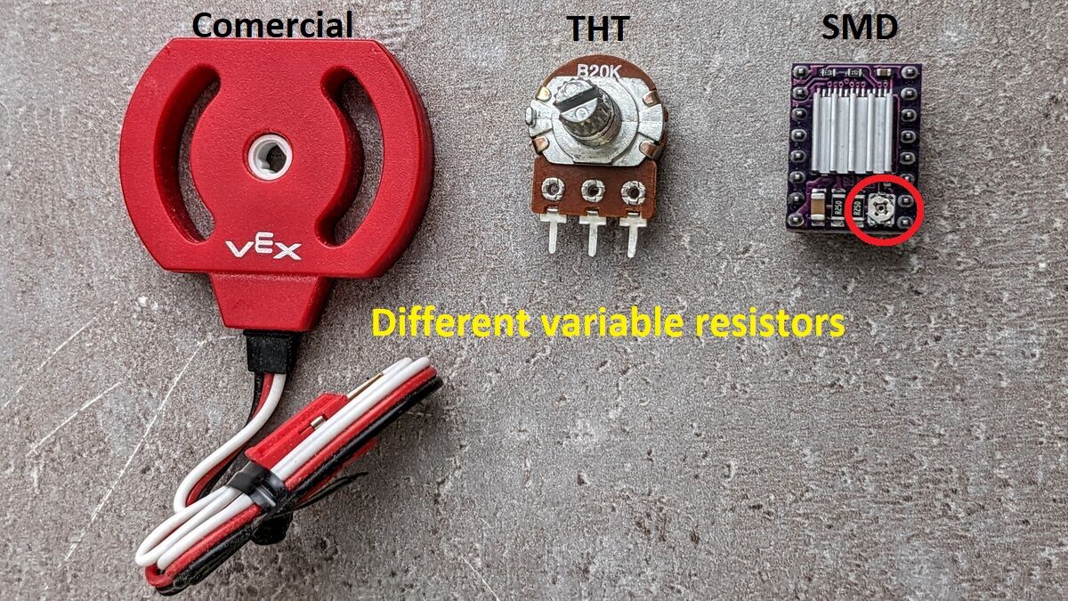
Variable linear resistors (potentiometers)
Mher one of our school’s art teachers joined us that day to learn about the sensors and their types. We started with variable resistors and Babken showed us different types that are found around us in everyday life.
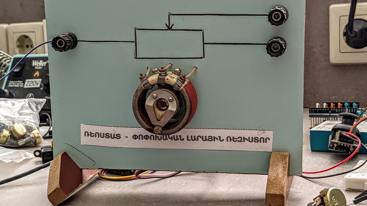
 Mher remembered that our school has an old educational stand of potentiometer so he found it and brout to test.
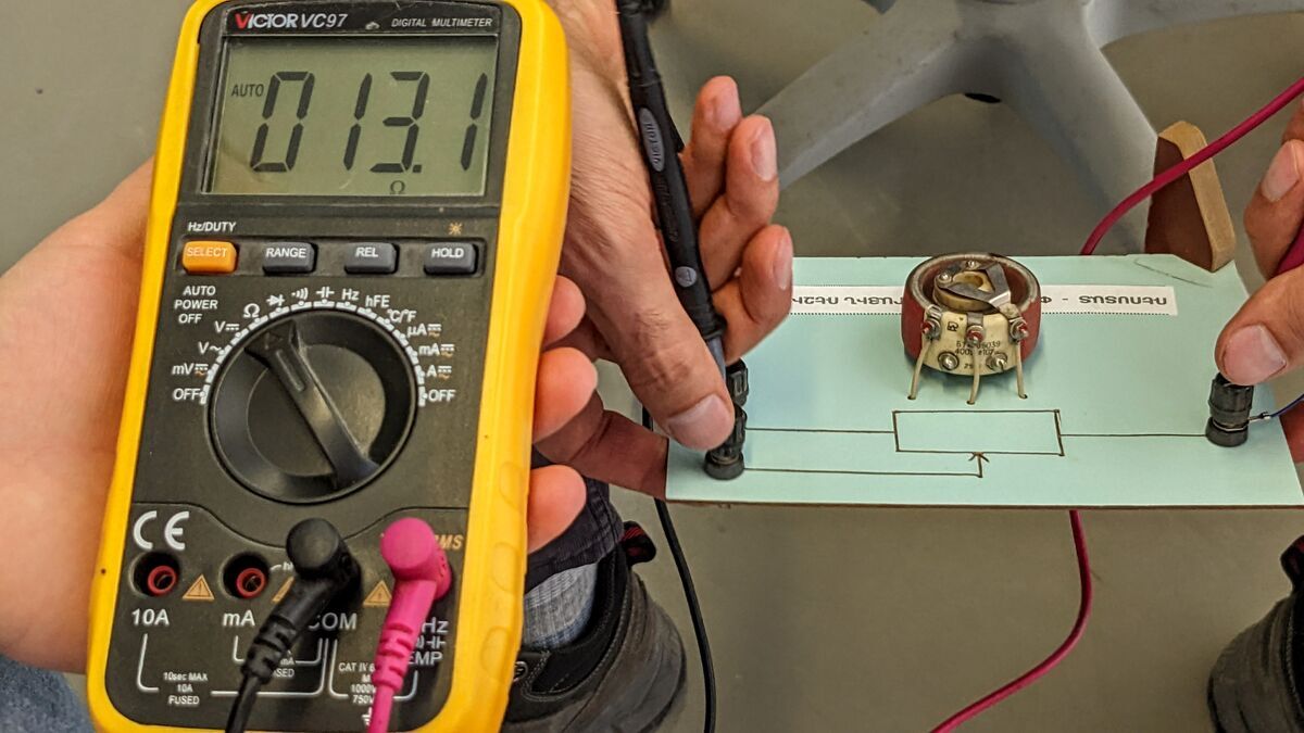
 we tested them with a multimeter to find their extreme values. In order to do that one should rotate the knob to the extreme points and compare values. Usually they start from 0 and go all the way to Kohms.
 Next we learned about voltage dividers and why do we need them: Voltage dividers can be used to allow a microcontroller to measure the resistance of a sensor. The sensor is wired in series with a known resistance to form a voltage divider and a known voltage is applied across the divider.(wikipedia)
LDR
LDRs are light dependent resistors that change their resistance based on light intensity applied to them. In oder to use one we need to build a simple circuit called voltage divider.
Voltage dividers can be used to allow a microcontroller to measure the resistance of a sensor. The sensor is wired in series with a known resistance to form a voltage divider and a known voltage is applied across the divider.(wikipedia)
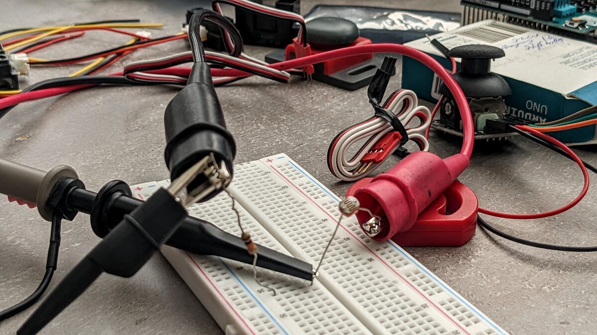 we connected the powr supply and the oscilloscope to see the changes.
We could see how the voltage reading was changing when the LDR was covered with hand resulting in less light falling on it.
IR range sensors
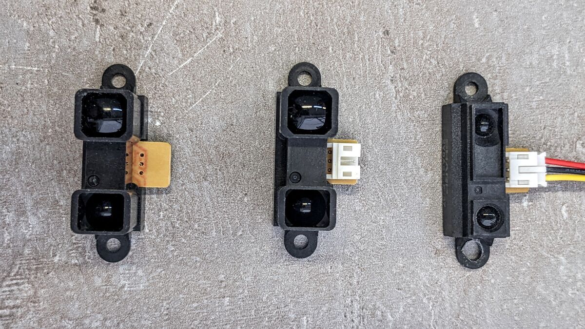 These sensors are very easy to work with since they already have a voltage divider, noise filter and what’s even more cool a modulated Infrared beam. This enables the sensor to exactly know whether the reading is coming from his source or it’s a foreign source like sun or light. We connected them to oscilloscpe and tested their behaviour.
Unfortunately no one took videos of that moment.
Ultrasonic sensor
In contrast to previous sensors this sensor is digital. This means that our microcontroller is not going to measure voltage differance but something else in our case pulse duration, in other cases it might be data or pulse counts.
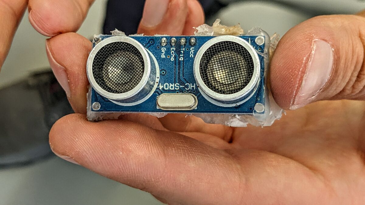 This sensor has 4 pins VCC, GND, Trigger and Echo.
As name implies the trigger needs a trigerring signal a 10ms pulse after which the echo pin sends back a pulse whose duration indicates the distance between the sensor and the obsticle.
This sensor has 4 pins VCC, GND, Trigger and Echo.
As name implies the trigger needs a trigerring signal a 10ms pulse after which the echo pin sends back a pulse whose duration indicates the distance between the sensor and the obsticle.
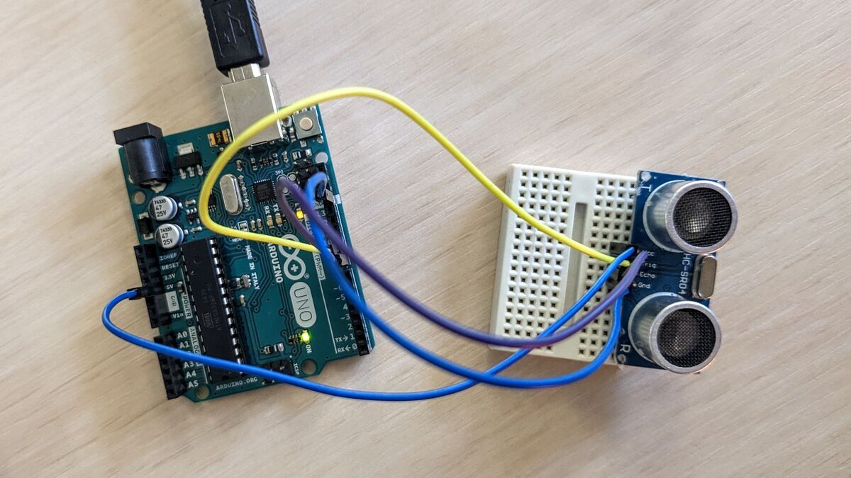 We used Arduino Uno to send the triggering pulse and test the sensor.
Here we connected the echo pin to oscilloscope to see how actually the sensor works.
We used Arduino Uno to send the triggering pulse and test the sensor.
Here we connected the echo pin to oscilloscope to see how actually the sensor works.
 Here is the video how it works.