8. Electronics Production
The main resource that helped us start was this great tutorial made by the Aalto Fablab in Finland. For example, we learnt that, as a rule of thumb, the cut depth should be around 75% the diameter of the tool.
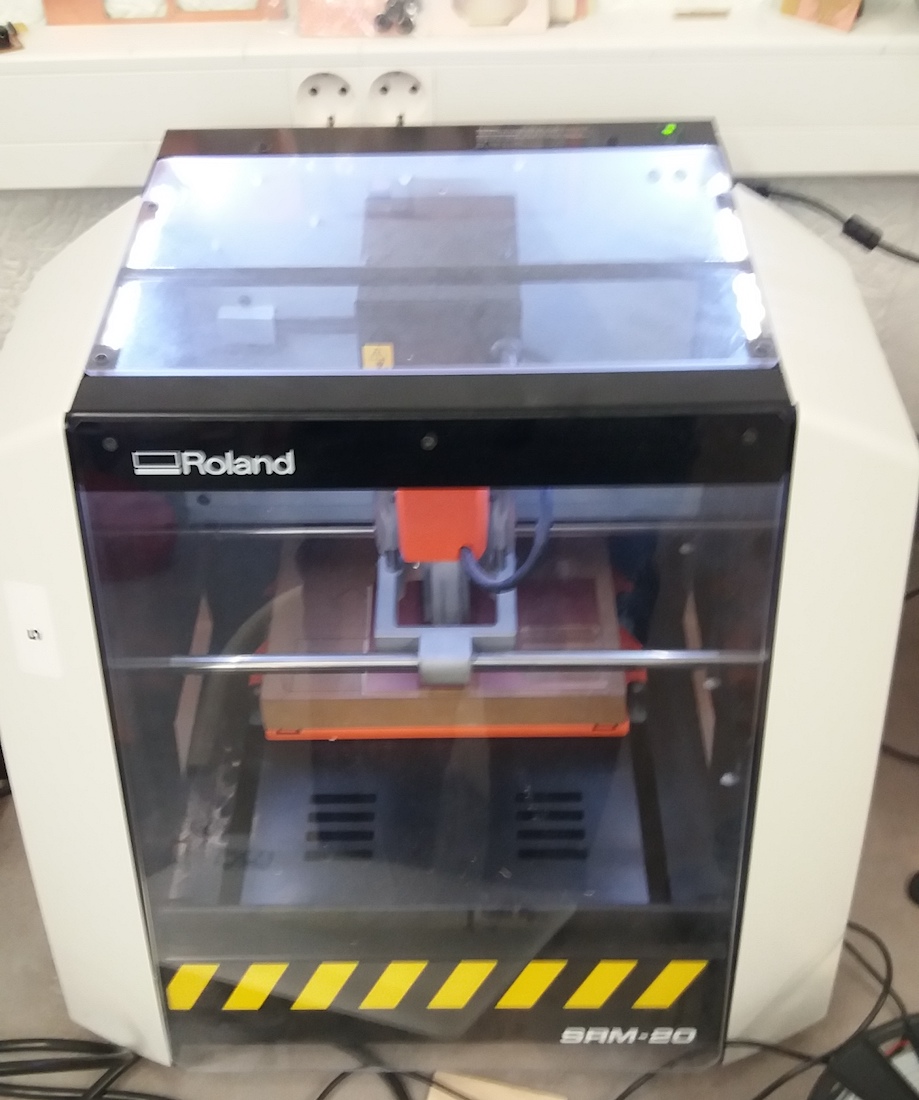
The CNC-machine we used was a Roland SRM-20.
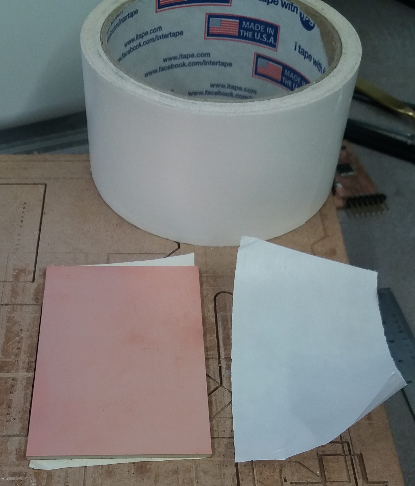
To install a new board on the MDF table, we used some double sided scotch tape. To improve the adherence, we sometimes use a clamp and to pieces of wood to tighten the board to the table. But we could also do it by hand, depending on the size of our board.
The software we used to control the CNC was “VPanel for SRM-20”:
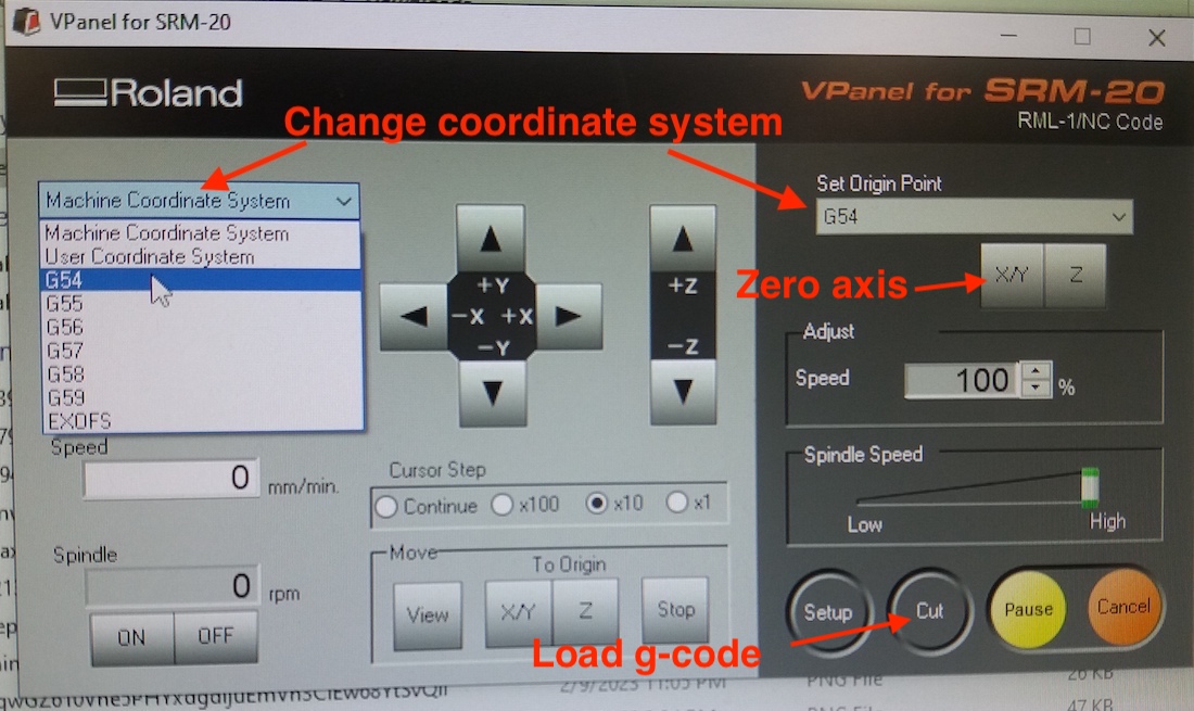
In order to zero the z-axis, we manually lower the bit close to the board. Once it’s pretty close, we use the appropriate hex key to release the bit and gently lower it until it’s touching the board. Once there is contact, we tighten the screw, and the z-axis is zeroed.
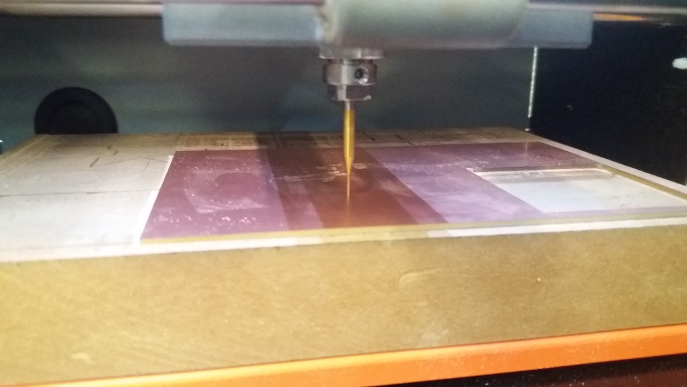
Once the machine was ready, we downloaded the png files to conduct our tests and used mods to generate the g-code. First, we used the 0.5mm bit to test in how many gaps it would go. (To cut the board, we used a 1/32 inches mill):
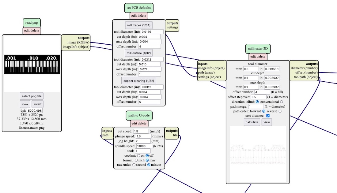
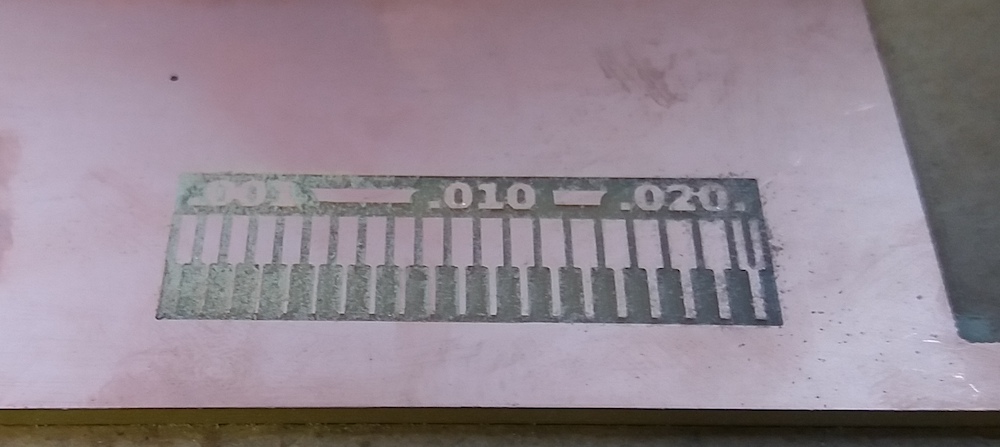
We noticed that the first line carved by the CNC was less and less deep and disappearing at the end. This meant that the table was not flat. A solution would have been to mill the whole table with a large bit at a certain height. However, to gain time, we decided to zero the CNC z-axis on the lower part of the table, so that it would carve even here.
For this test with the 0.5mm mill, it was only able to carve inside the 0.020 inch gap. Which is coherent, because 0.020 inch is equal 0.508 and 0.019 inch is equal to 0.4826mm.
Afterwards, we tried with a 0.1mm v-shaped bit:
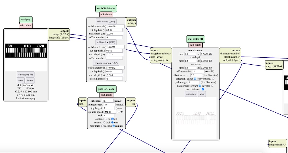
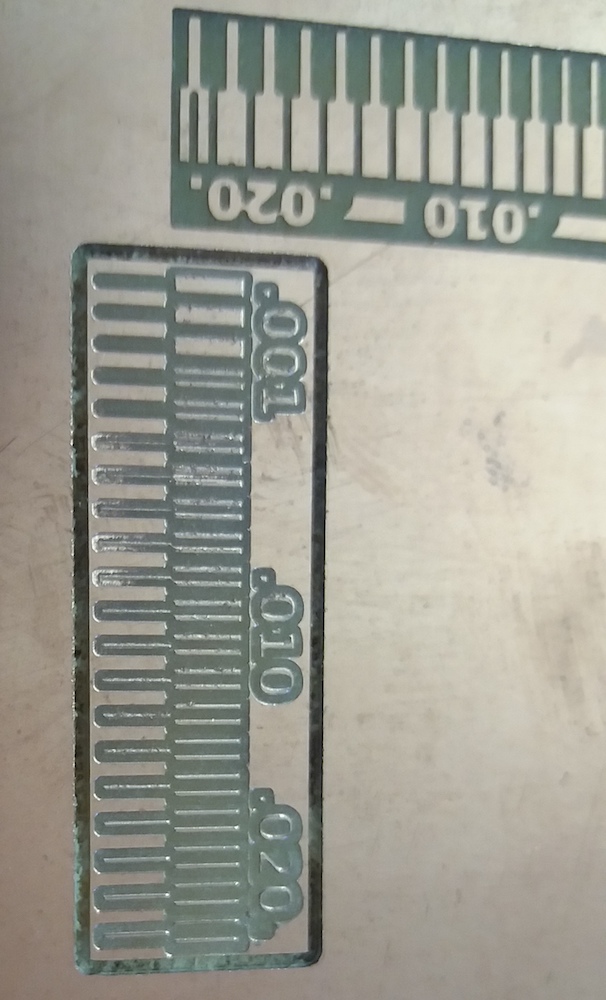
When we compared with the previous result, we saw that there was something wrong. It seemed that the bit carved much more than it was supposed to. I hypothesis was that, because of the uneven level of our table, we zeroed below the carved surface and, because of the v-shape, it cut much more than 0.1mm.
G code
Our instructor, Babken, told us that the g code can be read and that each line corresponds to something human understandable. For example, we deleted the M03 line in the g-code and the mill wasn’t rotating anymore, while the CNC was moving for the “air cut”.
Also we learned that G54 command tells the CNC machine where your part is located. From G54-G59 you can select different coordinate systems or “Work offsets” by simply changing G54 to another value. This might be helpful when you want to mill several jobs and don’t want to change the endmills back and forth. You can find more info here
%
G17
G21
G40
G49
G54
G80
G90
G94
T1M06
F90.0000
S11000
G00Z2.0000
M03     <- this line
G04 P1000
G00Z2.0000
G00X4.3253Y17.3941Z2.0000
G01Z-0.0930 F90.0000
F90.0000
G01X7.0460Y17.3941Z-0.0930
...