Week 4: Embedded Programming
✓ browse through the data sheet for your microcontroller
✓ write program for a microcontroller development board
✓ use different languages
✓ compare the performance and development workflows for other architectures
Group assignment: comparing controllers
For this assignment, we were lucky to have Onik Babajanyan, a 2022 Fab Academy graduate, who introduced us with microcontrollers during a workshop.
ATMega328P vs STM32 comparison
We compared these two controllers using their data sheets: ATMega328P and STM32 F303 xB or xC. We obtained the following differences:
| Feature | STM32 | ATMega328P |
|---|---|---|
| Register size | 32-bits | 8-bits |
| Operating conditions | 2 - 3.6 V | 2.7 - 5.5 V |
| Flash memory | 128 - 256 kB | 32 kB |
| SRAM | up to 40 kB | 2 kB |
| Clock speed | 4 - 32 MHz | 0 - 16 MHz at 4.5 - 5.5 V |
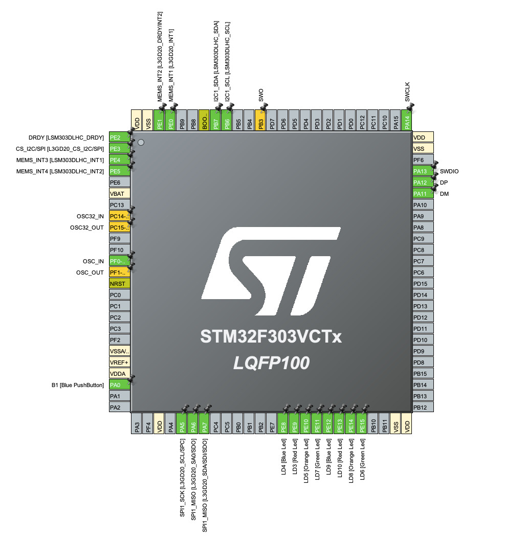
We also checked the differences in their pin configurations:
For the ATMega328P:

And for the STM32:
Development worflow for ATMega328P
Since this microcontroller is on an Arduino UNO, we can use the standard Arduino IDE. I already had it on my computer, so I just had to start a open a new project and I obtained the following starting file:
![]()
It is then quite straight forward to implement a project using C and the available Arduino libraries.
Development workflow for STM32
The development workflow for this microcontroller is quite more involved than for Arduino. For this part, this tutorial for the STM32 F3 Discovery and this video about STM32 were a great help.
Installing STM32Cube IDE
I downloaded and installed the STM32Cube IDE on MacOS but when trying to launch it, I encountered an error telling me that “STM32CubeIDE” is damaged and can’t be opened. After trying to reinstall the software, I found a fix on stackoverflow suggesting to use the following command:
sudo /Applications/STM32CubeIDE.app/Contents/MacOS/stm32cubeide
And it worked!
Starting a new project
When we start a new project with the STM32 Cube IDE, we are greeted with this screen:
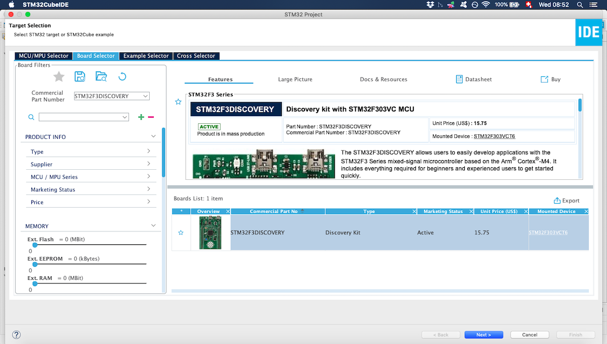
This screen enables us to rapidly find our board (STM32 F3 discovery), which will greatly simplify the configuration. If we would use a non standard board, we would have to go to the “MCU/MPU Selector” and we could select which MCU we would use.
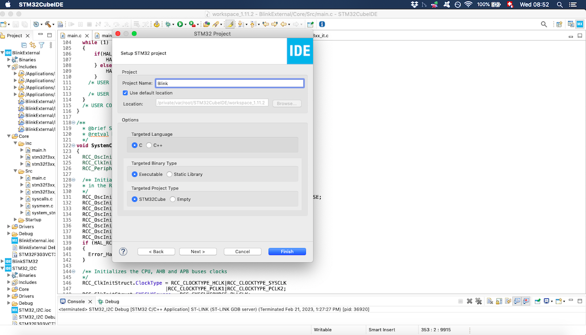
We can then name our project, as well as choose between few options like the programming language we want to use:
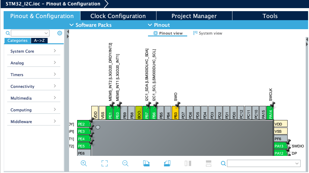
Once the project is created, we can use a graphical user interface to handle several things. The first one enables us to understand the pin mapping of the MCU:
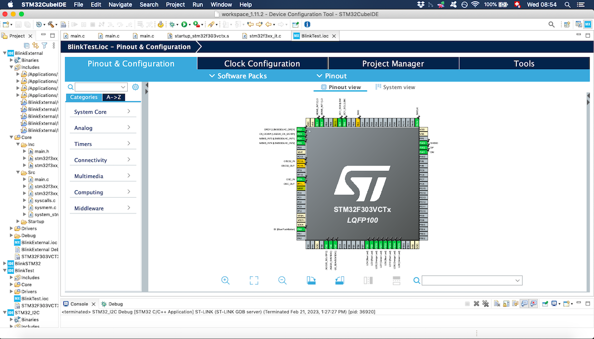
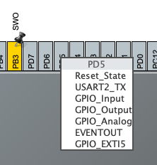
It is also possible to attribute a function to a specific pin:
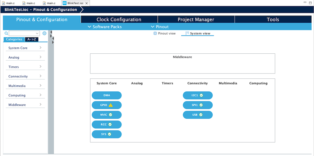
Another useful GUI is the System view. In my case, I could check here that the I2C1 was activated:
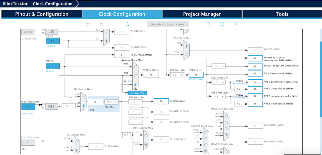
There are other interfaces, like the Clock Configuration panel or the Project Manager panel. However, I didn’t use these panels during this week.
The Clock Configuration would enable us to change the maximum MCU frequency, for example:
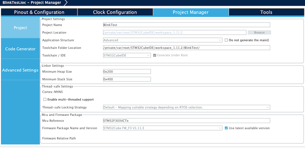
The Project Manager would be useful if we wanted for example to change the heap or stack sizes:
Once we are happy with our settings, we can press Save and the code will be generated. The main.c looks then like this:
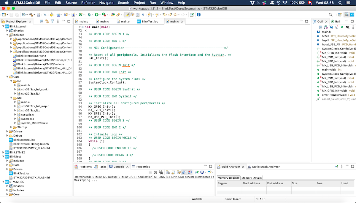
It is more complicated than the Arduino version, the tradeoff for the Arduino simplicity is performance. There is however a way to make programming for the STM32 a bit easier: using the Hardware Abstraction Layer (HAL) API. That’s what I did this week.
Programming
Arduino in C
For this week, I wanted to later understand a simple program in Assembly. Since one of the simplest programs on Arduino is to blink the built-in LED, I started with its C version taken from the Basic Examples directly available in the IDE:
void setup() {
  pinMode(LED_BUILTIN, OUTPUT);

}

void loop() {
  digitalWrite(LED_BUILTIN, HIGH);
  delay(1000);
  digitalWrite(LED_BUILTIN, LOW);
  delay(1000);
}
From this data sheet to the Arduino UNO, we can know that the built-in LED is connected to the pin D13:
Therefore, instead of
pinMode(LED_BUILTIN, OUTPUT);
we could have written:
pinMode(13, OUTPUT);
Arduino in assembly
Blink built-in LED with delay in C
To try to understand a tiny bit os Assembly language, I used this video tutorial on how to use assembly to blink an LED. The code below in Assembly directly comes from this tutorial and I didn’t change it, except for the index of the register to correspond to the built-in LED in this section and the numerical values for the loops in the next section.
In order to use Assembly with Arduino, we need to have a .ino file written in C. I will not show the code here since I am focusin on Assembly, but it is available at the bottom of this page with the other source files.
The .S file with the Assembly code looks like this:
#define __SFR_OFFSET 0x00
#include "avr/io.h"

.global start
.global led

start:
  SBI   DDRB,5        ;set bit in the 5th DDR register of port B to 1 (output)
  RET

led:
  CPI   R24, 0x00     ;compare the value in register 24 passed as parameter to the function to 0x00
  BREQ  ledOFF
  SBI   PORTB,5       ;set bit in the 5th PORT B register to 1 (HIGH)
  RET

ledOFF:
  CBI   PORTB, 5      ;set bit in the 5th PORT B register to 0 (LOW)
  RET
The start and led functions used here are called from the .ino file. The delay() function is implemented in the .ino. I first had to look up all the instructions to have an idea of what was this program doing. I used this manual concerning the instructions set for the 8-bit AVR devices.
| Instruction | Meaning | #Clocks |
|---|---|---|
| SBI | Set Bit in I/O Register | 2 (AVRe) / 1 (else) |
| RET | Subroutine Return | 4 / 5 |
| CPI | Compare with Immediate | 1 |
| BREQ | Branch if Equal | 1 / 2 |
| CBI | Clear Bit in I/O Register | 2 (AVRe) / 1 (else) |
I then tried to understand what were these DDRB and PORTB. From this Arduino documentation, I found that PORTB maps digital pins 8 to 13. The same documentation enabled me to understand what was the relation between PORTB and DDRB: “Each port is controlled by three registers, which are also defined variables in the arduino language. The DDR register, determines whether the pin is an INPUT or OUTPUT. The PORT register controls whether the pin is HIGH or LOW, and the PIN register reads the state of INPUT pins set to input with pinMode().”
For example, this instruction:
SBI DDRB,5
corresponds to this C code:
pinMode(LED_BUILTIN, OUTPUT);
Blink built-in LED with delay in Assembly
We can go further and also implement the delay in Assembly instead of C. The first part of the code is the same as in the presious section and I show below only the new code:
...

led:
  ...
  RCALL myDelay
  RET

ledOFF:
  CBI   PORTB, 5      ;set bit in the 5th PORT B register to 0 (LOW)
  RCALL myDelay
  RET

.equ  delayVal, 10000 ;initial count value. Defines the actual delay

myDelay:
  LDI   R20, 100              ;initial value of the outer loop
outerLoop:
  LDI   R30, lo8(delayVal)    ;puts the low byte of delayVal into register R30
  LDI   R31, hi8(delayVal)    ;puts the high byte of delayVal into register R31
innerLoop:
  SBIW  R30, 1                ;subtract 1 to the 16-bits value in R30 and R31
  BRNE  innerLoop             ;jump to innerLoop: if countVal is not equal to 0

  SUBI  R20, 1                ;subtract 1 from value present in R20
  BRNE  outerLoop
The new instructions have the following meaning:
| Instruction | Meaning | #Clocks |
|---|---|---|
| LDI | Load Immediate | 1 |
| SBIW | Subtract Immediate from Word | 2 |
| BRNE | Branch if Not Equal | 1 / 2 |
| SUBI | Subtract Immediate | 1 |
Since I struggled to understand how this delay works, I decided to run a quick test by setting larger values for delayVal and R20 register in order to time the blinking by hand with a stopwatch. I chose a value for delayVal which was close to the maximum value I could put in a 2 bytes integer. For the outer loop counter initial value stored in R20, I had 1 byte at my disposal.
For delayVal = 65000 and R20 = 200, I measured the following blinking times:
| Time [s] | |
|---|---|
| Sample 1 | 3.24 |
| Sample 2 | 3.23 |
| Sample 3 | 3.30 |
| Sample 4 | 3.22 |
| Sample 5 | 3.24 |
| Average | 3.246 |
| Standard Deviation | 0.031 |
I then had to calculate a theoretical value according to my understanding of this code:
I am not sure how many clock cycles BRNE needs. I am guessing that if it has to branch, it will be 2 clock cycles and if it doesn’t, it will need only 1. To test this hypothesis, I calculated the total time with the 2 values and obtained:
| BRNE # Clocks | Approximate calculated time [s] |
|---|---|
| 2 | 3.25 |
| 1 | 2.44 |
Since the first value is much closer to the measured time, I suppose that my hypothesis was correct, provided that the rest of the calculation is correct. I calculated the time following this formula (for BRNE #Clocks = 2, outer loop initial value = 200, inner loop initial value = 65000 and 16MHz):
Time = 200 * (2 * #LDI + 1 * #SUBI + #BRNE_out * 2 + 65000 * (#SBIW * 2 + #BRNE_in * 2))
This calculation considers that all BRNE instructions need 2 clock cycles, which isn’t true. It is however close enough to reality for my purpose.
Sketch memory use comparison
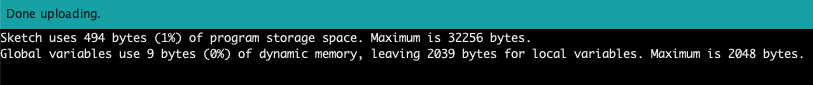
One of the reasons that one would want to use Assembly over C is performance. One of the ways to measure performance is to look at the memory used by each sketch. Indeed, these sketches needed less memory when using more Assembly code:
Blinking LED using C:

Blinking LED using Assembly and C for the time dely:

Blinking LED using Assembly:
Blinking with STM32
I explained above the basic worflow to program the STM32 F3 Discovery. I followed here the same workflow and just had to modify the while loop inside the main function in this way:
while (1)
  {
      HAL_GPIO_TogglePin(GPIOE, GPIO_PIN_9);
      HAL_Delay(100);
      HAL_GPIO_TogglePin(GPIOE, GPIO_PIN_10);
      HAL_GPIO_TogglePin(GPIOE, GPIO_PIN_9);
      HAL_Delay(100);
      HAL_GPIO_TogglePin(GPIOE, GPIO_PIN_11);
      HAL_GPIO_TogglePin(GPIOE, GPIO_PIN_10);
      HAL_Delay(100);
      HAL_GPIO_TogglePin(GPIOE, GPIO_PIN_12);
      HAL_GPIO_TogglePin(GPIOE, GPIO_PIN_11);
      HAL_Delay(100);
      HAL_GPIO_TogglePin(GPIOE, GPIO_PIN_13);
      HAL_GPIO_TogglePin(GPIOE, GPIO_PIN_12);
      HAL_Delay(100);
      HAL_GPIO_TogglePin(GPIOE, GPIO_PIN_14);
      HAL_GPIO_TogglePin(GPIOE, GPIO_PIN_13);
      HAL_Delay(100);
      HAL_GPIO_TogglePin(GPIOE, GPIO_PIN_15);
      HAL_GPIO_TogglePin(GPIOE, GPIO_PIN_14);
      HAL_Delay(100);
      HAL_GPIO_TogglePin(GPIOE, GPIO_PIN_8);
      HAL_GPIO_TogglePin(GPIOE, GPIO_PIN_15);
      HAL_Delay(100);
      HAL_GPIO_TogglePin(GPIOE, GPIO_PIN_8);
  }
And here is the result:
I2C communication: adding a button the hard way
Arduino to Arduino communication
I have to admit that I first tried STM32 to Arduino communication but since I couldn’t make it work, I tried to make two Arduinos communicate. I started from the code given in this tutorial
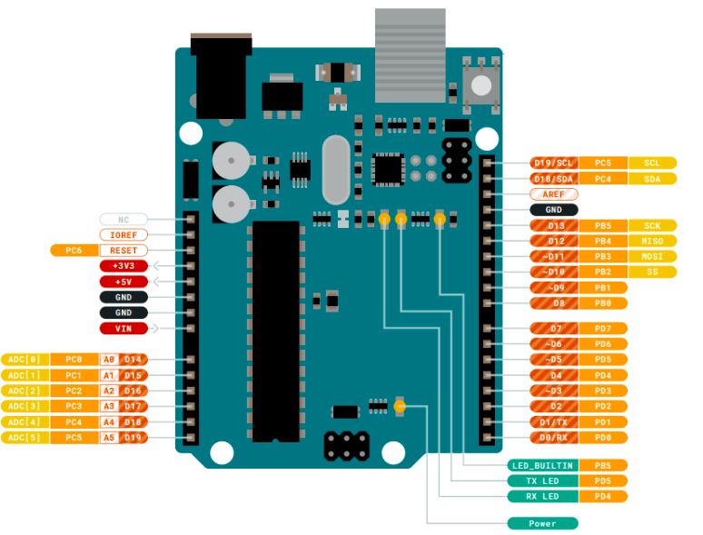
To wire the Arduino boards correctly, I needed to know which pin was SDA and which one was SCL. From the pin-out diagram of the ATMega328P shown above, we can know that the SDA corresponds to the port pin PC4 and the SCL corresponds to the port pin PC5. From the Arduino UNO board pin mapping shown above, we know that PC4 corresponds to A4 and PC5 to A5. Therefore, we need to connect the two A4 together and the two A5 together. Furthemore, we also need to connect the one GND from each board together.
The code for the primary device:
#include <Wire.h>

#define SLAVE_DEVICE_ID 0x33

bool ledON = true;

void setup()
{
  Wire.begin();
  Serial.begin(9600);
}

void loop()
{
  Wire.beginTransmission(SLAVE_DEVICE_ID);  //we need to know the device ID on from the secondary in advance
  if (ledON) {
    Wire.write('1');
    ledON = false;
  } else {
    Wire.write('0');
    ledON = true;
  }
  Wire.endTransmission();

  delay(200);
}
The code for the secondary device:
#include <Wire.h>
byte xByte = 0;
#define DEVICE_ID 0x33

void setup()
{
  pinMode (13, OUTPUT);
  Wire.begin(DEVICE_ID);            //we need to put this same device ID on the primary
  Wire.onReceive(receiveEvent);
  Serial.begin(9600);
  Serial.println("Begin");
}

void receiveEvent(int bytes)
{
  xByte = Wire.read();
  Serial.println("received");
  Serial.println(xByte);
}

void loop()
{
  if (xByte == 49)          //we test the received byte to see if it corresponds to '1' (but why is '1'==49?!)
  {
    digitalWrite(13, HIGH);
  }
  else
  {
    digitalWrite(13, LOW);
  }
}
The serial monitor on the receiving part looked like this:
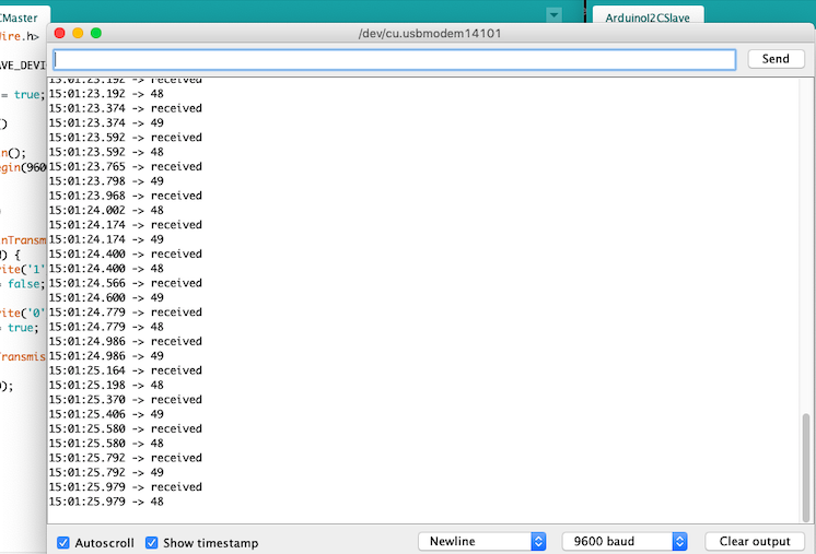
In order to make it work, I had to first experiment and print the received value on the receiving side and then I could write the comparison: if (xByte == 49). However, I don’t understand why the char ‘1’ sent translates to 49.
STM32 to Arduino communication
Once I managed to make it work on Arduinos, I proceeded to implement the primary side on the STM32 F3 Discovery board. I used this tutorial, this one and this one. First I needed to identify the SDA and SCL pins on the STM32:
Using the pin-out GUI from the STM32 Cube IDE, it was pretty easy. We could however read the data sheet in order to reach the same conclusions:
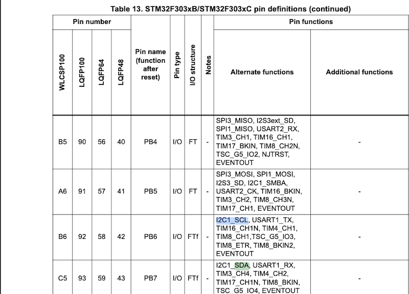
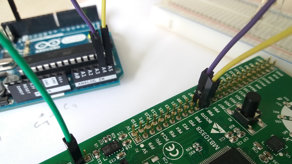
For the wiring, again I needed to connect two GND together. For the SDA connection, I wired the A4 from the UNO to the PB7 from the STM32. For the SCL connection, I connected the A5 from the UNO to the PB6 from the STM32.
Relevant code for the primary implemented on the STM32:
...

#define I2C_SLAVE_ADDRESS (0x33<<1)

...

while (1)
  {
    if(HAL_GPIO_ReadPin(GPIOA, GPIO_PIN_0)) {
          HAL_GPIO_TogglePin(GPIOE, GPIO_PIN_10);
          HAL_I2C_Master_Transmit(&hi2c1, I2C_SLAVE_ADDRESS,(uint8_t*)'1', 1, 20);
          HAL_Delay(100);
      } else {
          HAL_I2C_Master_Transmit(&hi2c1, I2C_SLAVE_ADDRESS,(uint8_t*)'0', 1, 20);
          HAL_Delay(100);
          HAL_GPIO_WritePin(GPIOD, GPIO_PIN_5, 0);
      }
  }

...
Again, I had to experiment first before setting the correct value to compare with on the Arduino receiving side.
Conclusion
This week was very fun for me. I had written code for the Arduino before but it was the first time I used another microcontroller. It was also very exciting to try to understand some Assembly, even though I am still very far from writing any real program by myself using this language.
It was also interesting to dive into data sheets to understand what is under the hood of these microcontroller, and this is something that will definetely be handy in the following weeks.