Week 12: Molding and casting
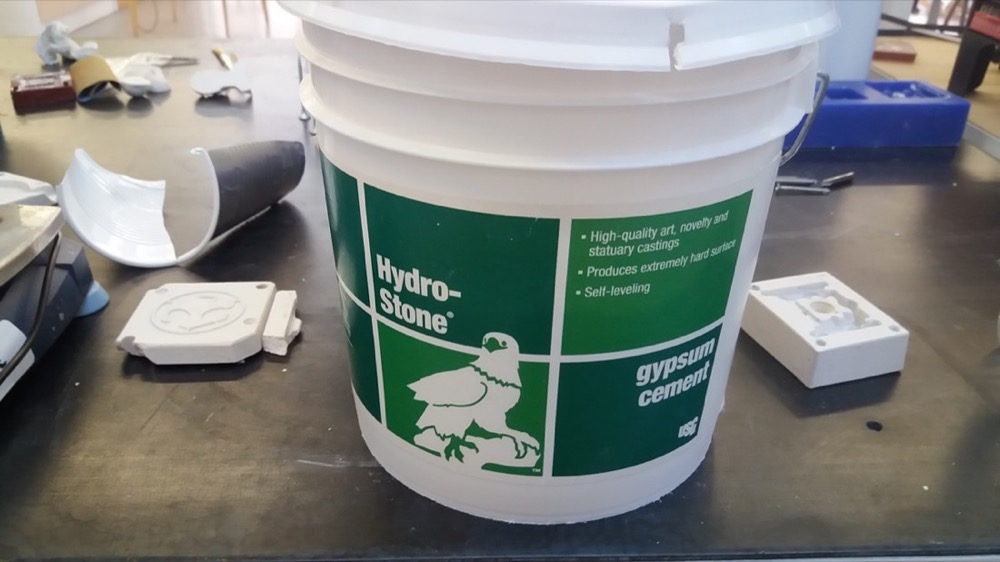
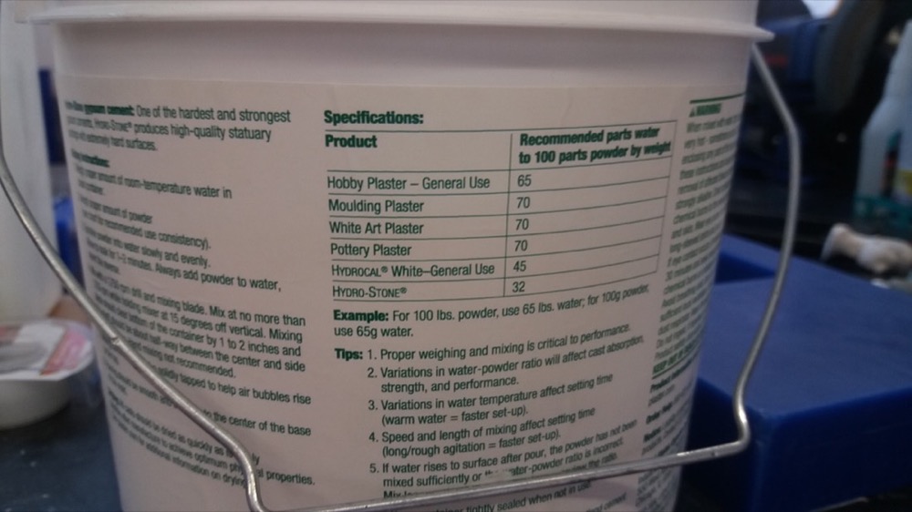
✓ review the safety data sheets for each of your molding and casting materials
✓ make and compare test casts with each of them
✓ design a mold around the stock and tooling that you’ll be using
✓ mill it (rough cut + three-axis finish cut)
✓ use it to cast parts
This week, I had in mind to make a very basic gamepad with 8 buttons. As introduction to the topic, I watched a tutorial of the Aalto Fablab concerning 3D modeling for designing moulds. I also watched a quick video about how gamepads are made.
Design
I decided to make the gamepad in two parts: a bottom part which would be made out of hard material, and a thinner top part which would contain the PCB and would be made out of a soft material.
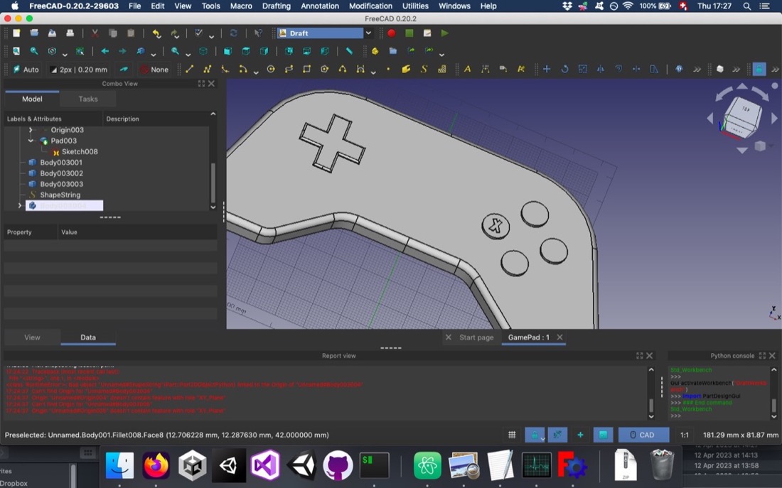
I first designed the bottom part:
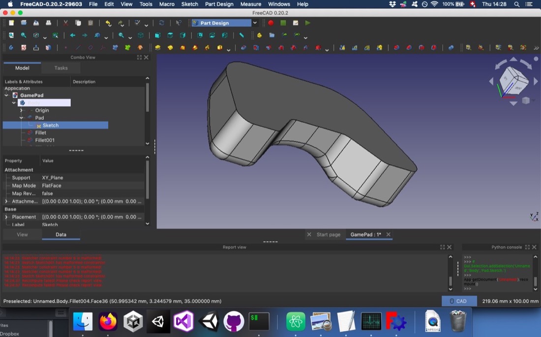
In order to make the demoulding of the piece possible, I had to add draft angles on the faces parallel to the demoulding direction:
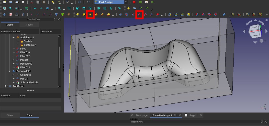
I used the additive and subtractive loft tools in freecad:
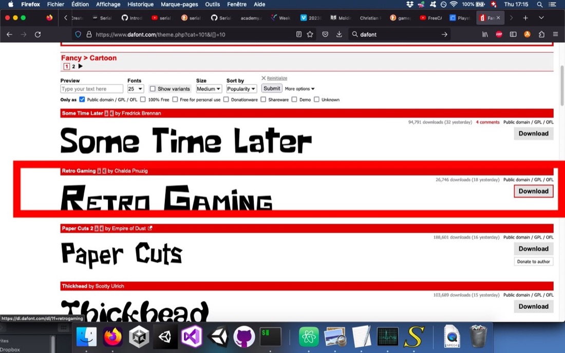
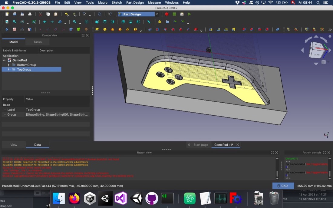
And then the top part, which would have some buttons with some letters. I chose a font free of rights:
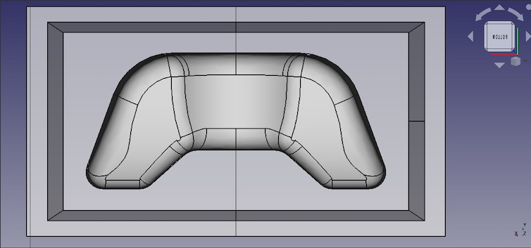
Since the top part would be made of a soft material, I could directly make it in the wax mould, so I had to design a negative mould with a boolean operation:
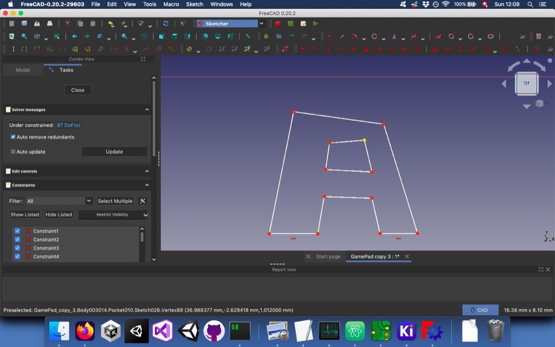
After realizing that the letters were too thin for the endmill that I would use, I had to modify them. I didn’t find how to simply convert a letter to a sketch in Freecad, so I just traced over each letter:
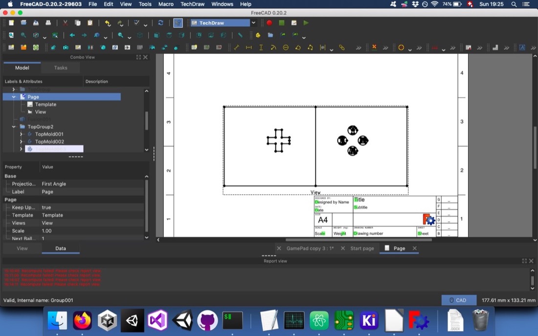
Eventually, I exported the buttons as an svg to be able to carve them with a 2D tool, which would be much simpler than 3D milling them, as we’ll see later:
Generating g code
This part was, surprisingly for me, the most frustrating this week. I had problems with mods that bugged me down and, eventually, after many many trials, I used ParWorks 3D.
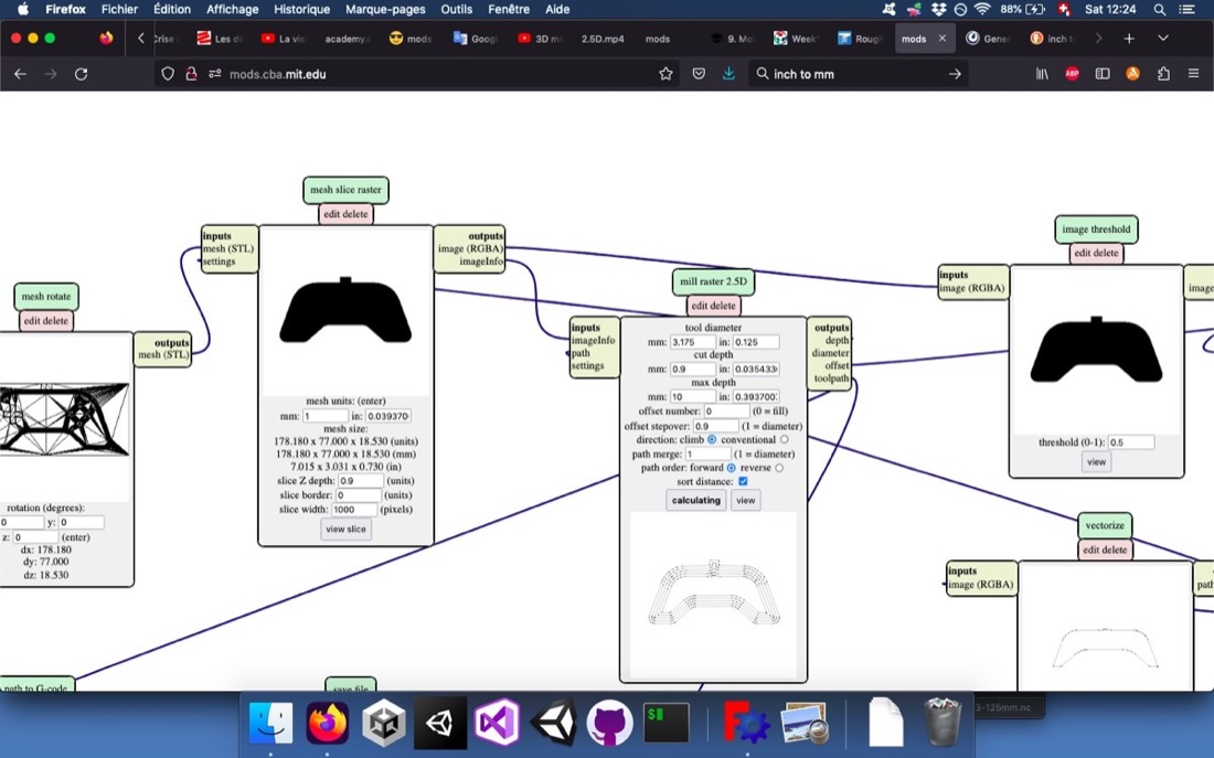
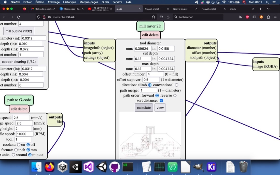
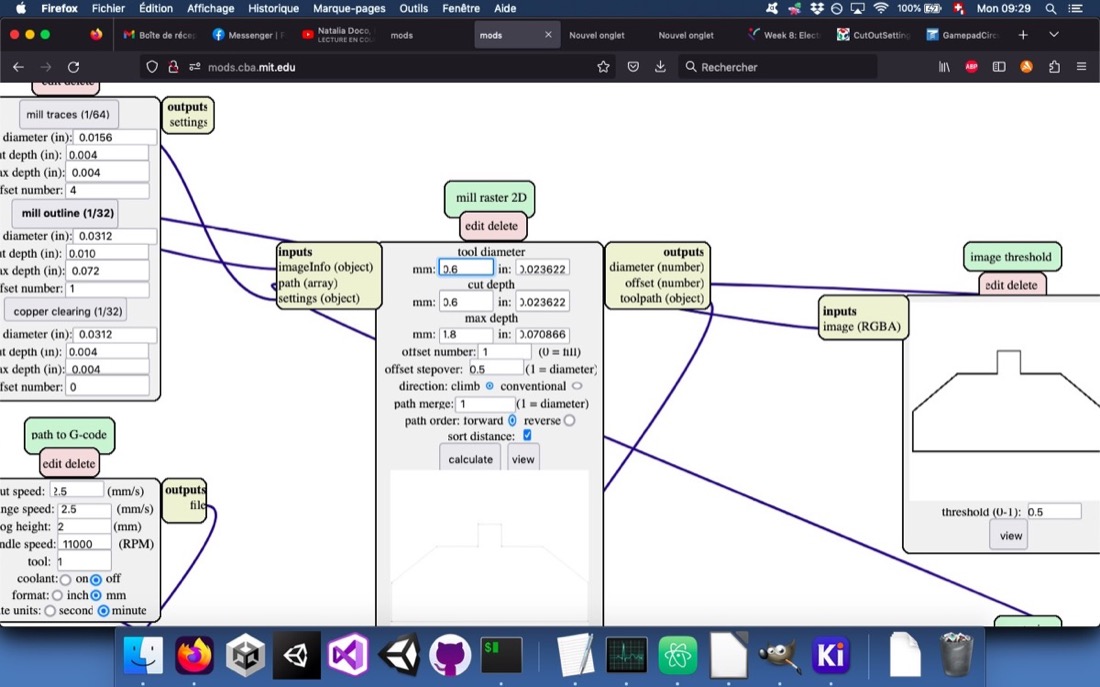
In mods, I started by generating the gcode with the 2.5D raster milling program. I had to tune a bit the cut depth in order to get the buttons carved:
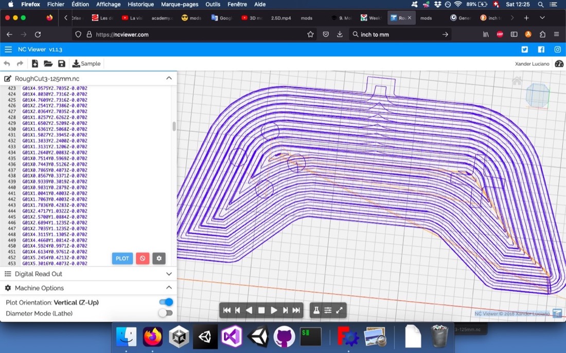
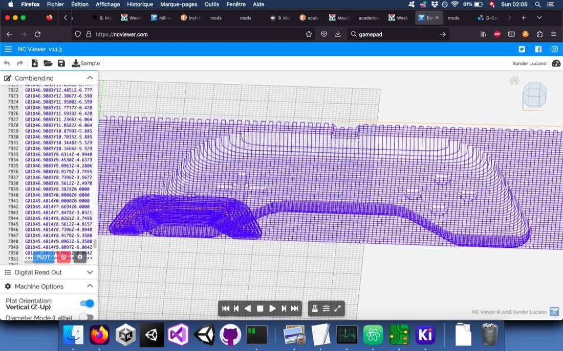
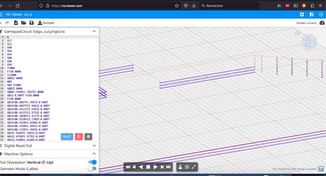
It looked fine in NCViewer:
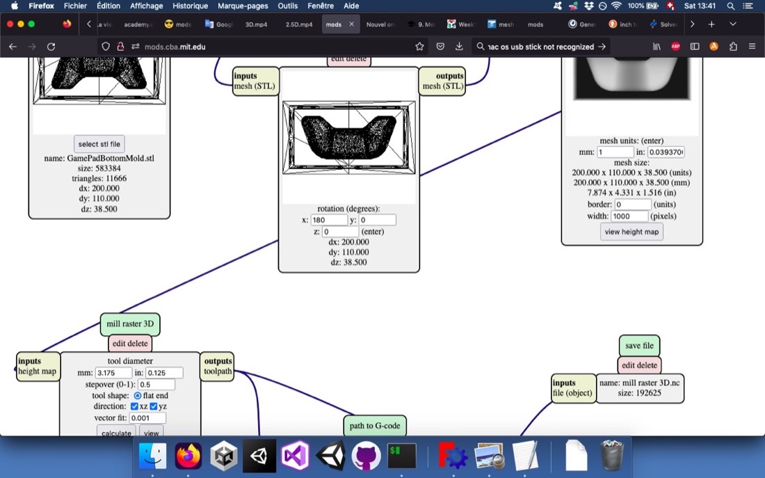
I then proceeded to calculate the finishing cut with the 3D milling program. First, with the default parameters, the calculation seemed to be stuck and no output was given. Babken, my instructor, told me to change the mesh units from 25.4 mm to 1 mm:
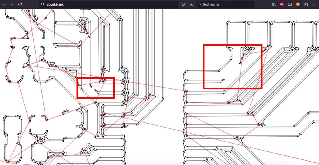
This worked and I got an output file. However, the scale seemed strange to me. To check this, I pasted the coordinates of one of the finish cut gcode file into the rough cut gcode file:
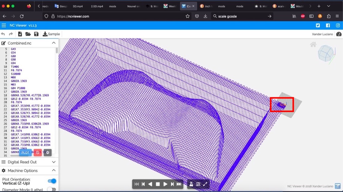
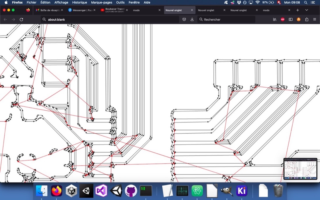
The tiny red rectangle shows the visualization of the rough cut… Then, Babken told me that there might be a gcode command that tells the program in which unit it is. Indeed, the G20 command means that the coordinates are in inches and G21 stands for mm. I thought that if I would copy paste the whole gcode (and not only the coordinates), the paths would have the same size in the gcode visualizer. However, if the scale difference was less dramatic, the paths were still not the same size:
At this point, I gave up on mods and switched to ParWorks3D. As Anoush managed to cut her mould with mods, I learnt that the gcode files I generated would actually work!
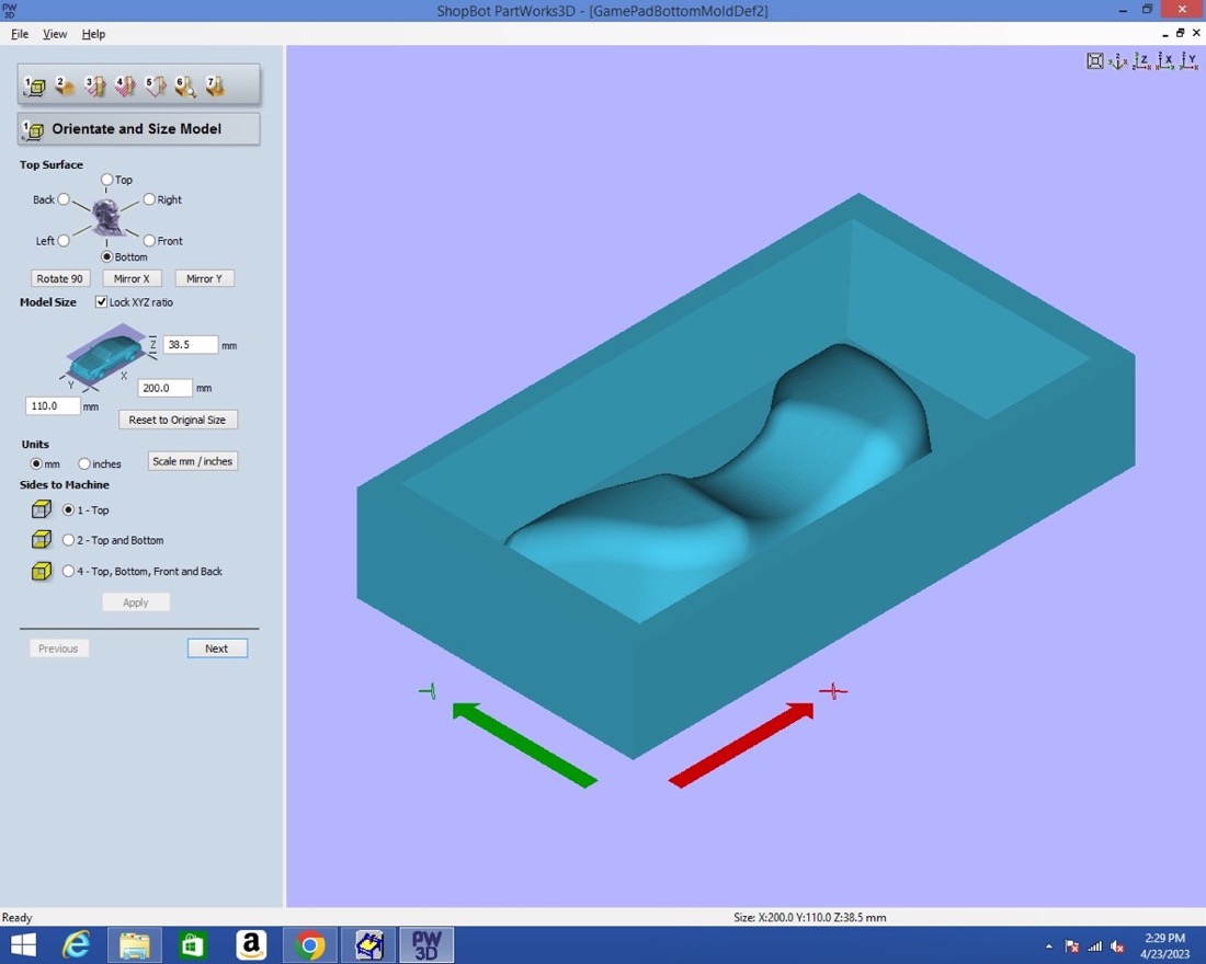
The first step in ParWorks3D enables us to orient and scale our piece:
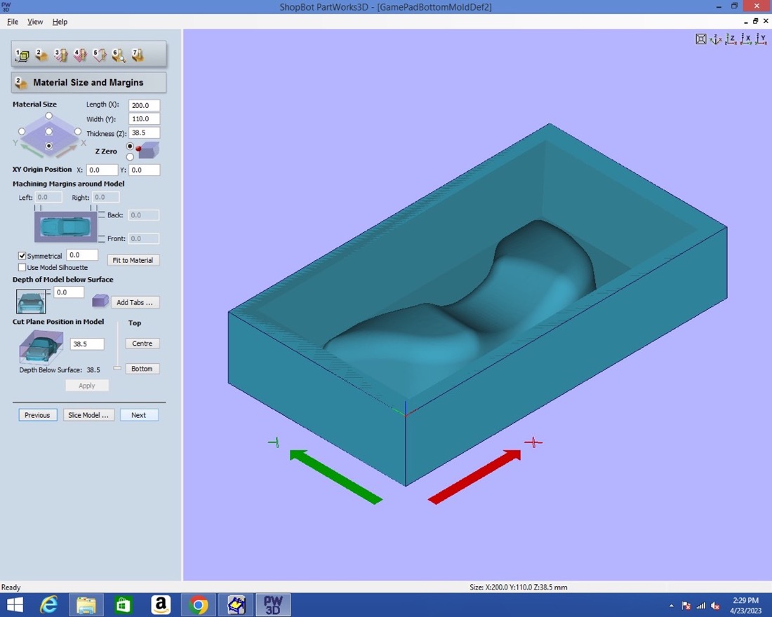
In the second step, it is important to set correctly the zero (as I would learn later):
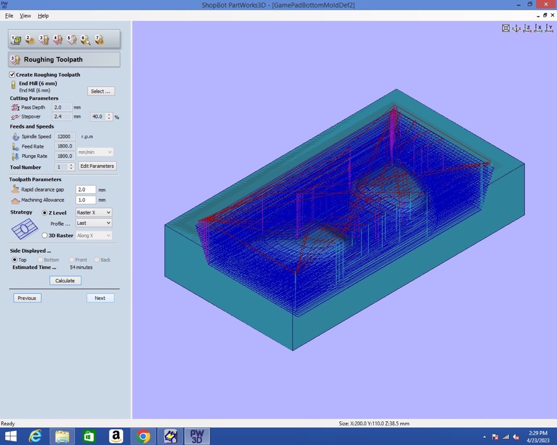
For the rough cut, I used a 6mm flat nose endmill:
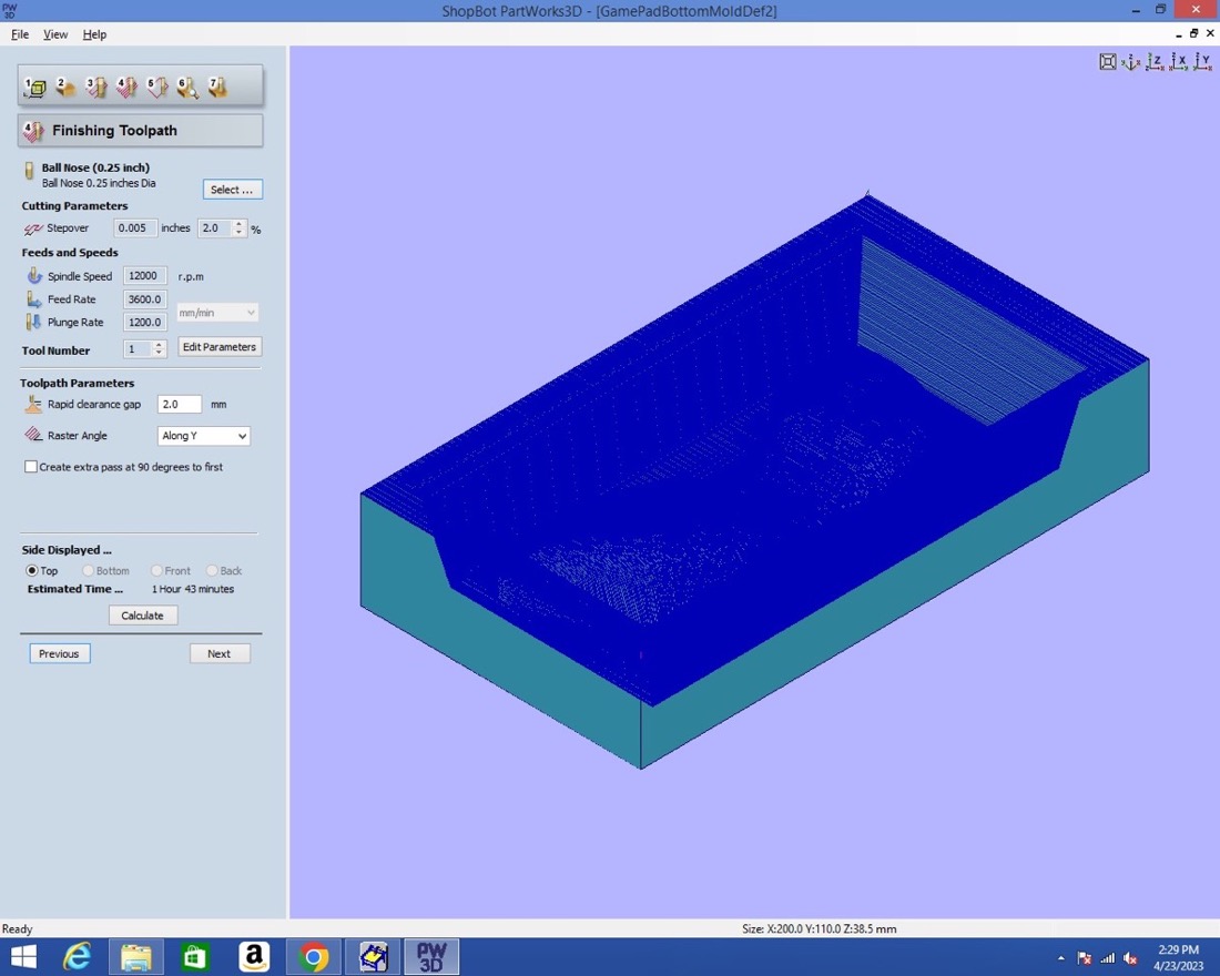
For the finish cut, I used a 1/4 inch ball nose endmill:
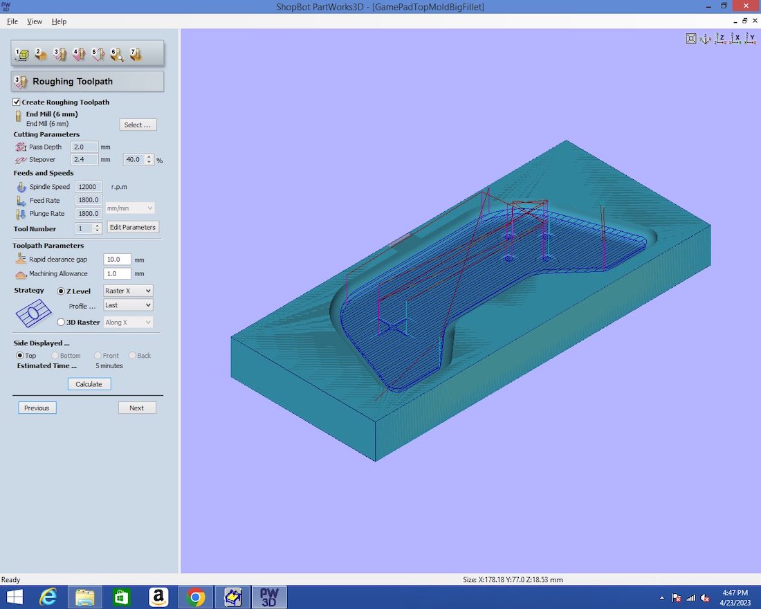
For the top mould, I proceeded in the same way. For the rough cut:
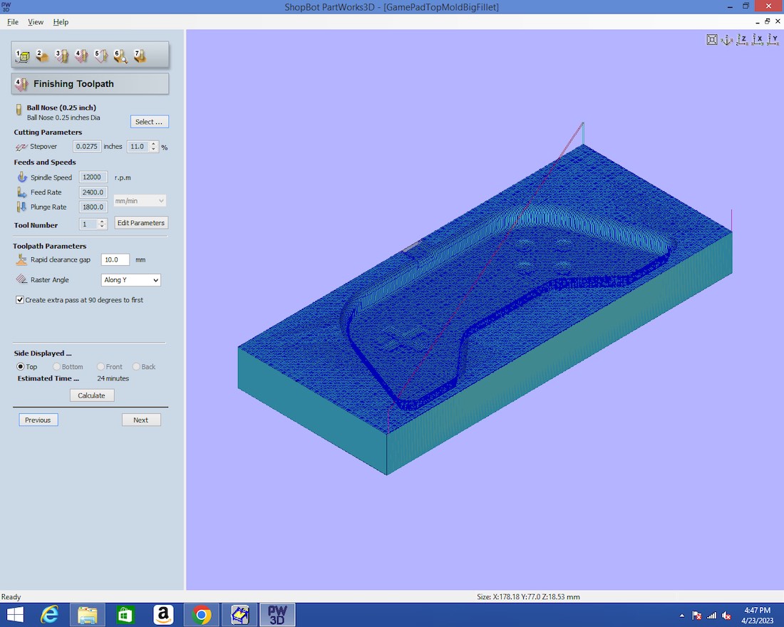
For the finish cut:
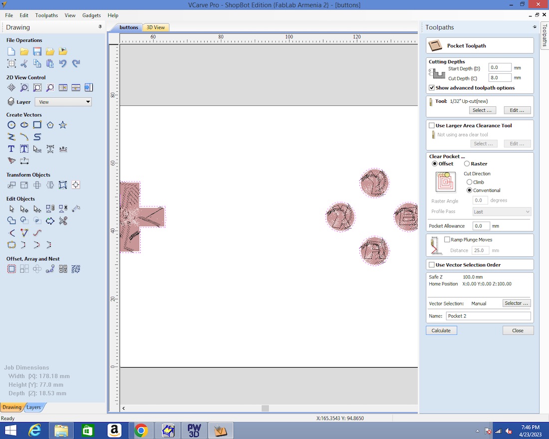
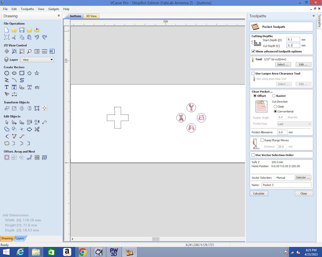
In addition to that, I carved the buttons and letters using the Vcarve 2D tool. I first generated the toolpath for the buttons:
And then for the letters:
Making the moulds
Moulding the bottom part
For working with the Shopbot, Mkhitar, a voluteer at the Fablab Dilijan, helped me a lot and I want to thank him a lot for this!
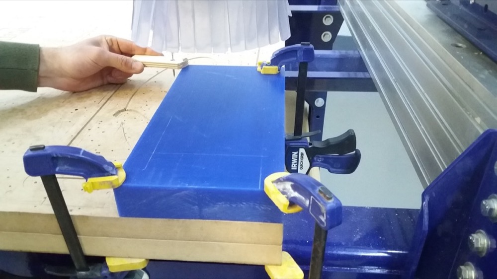
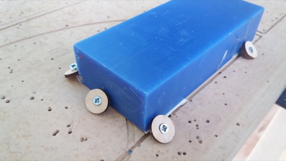
To secure the wax to the sacrificial layer, I first used some double face scotch tape. As it wasn’t enough, Mkhitar, helped me to add some clamps on three of the corners:
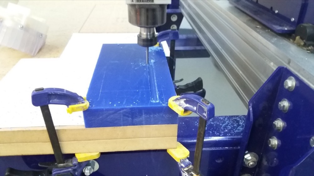
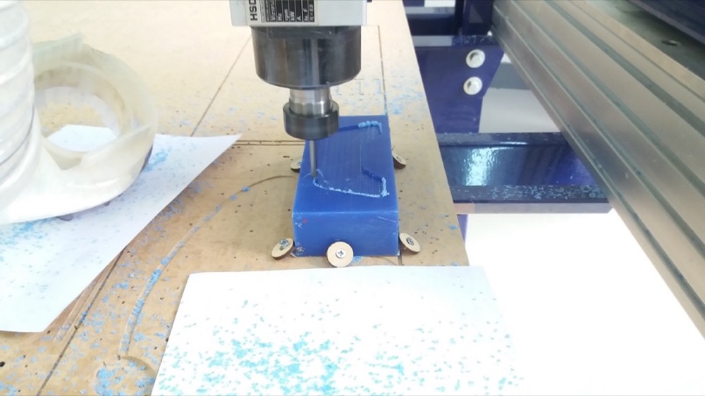
Start of the rough cut:
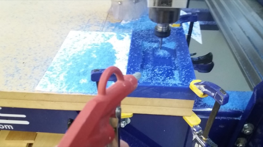
I used pressurized air to remove the wax chips from a safe distance:
After the rough cut was finished, I touched the computer with my foot and it shut down. This caused the loss of the XY zero. Since I remembered that the position should be an integer number of cm, I was able to recover the XY zeroing by measuring the approximate position of the spindle and rounding up or down to the closest cm.
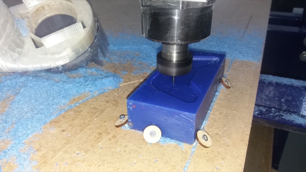
Finish cut in progress:
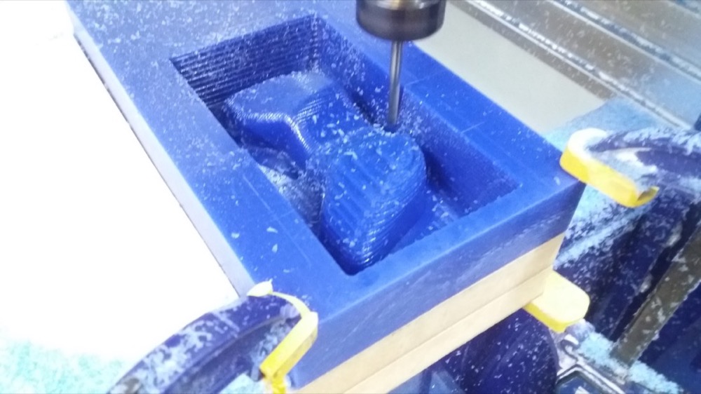
We had to do some breaks from now and then to let the Shopbot cool down since it was a long job:
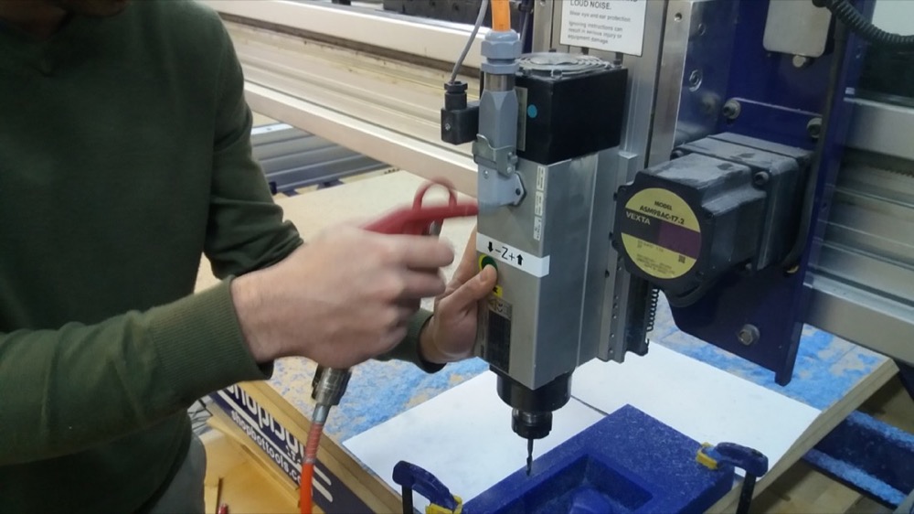
After starting the finishing work, I was adviced to reduce the Stepover. I remade the file for the finish cut after reducing the Stepover and started over the job. Unfortunately, since the computer had been restarted inbetween, I lost some of the settings I set in PartWorks3D. Most importantly, the zero by default is in the middle of the piece, but I thought that it was still on the bottom left corner. The spindle started with an unexpected trajectory, which I promptly stopped. But it probably hit a boundary, which caused the loss of the XY zeroing again! Mkhitar helped me to zero it by using small planks of wood pressed against the MDF sacrificial layer close to the (0,0) of the machine. We let the endmill barely touch the wood and then subtract half a diameter of the millbit.
After I recovered the zero, I started the finish cut. This time, it ran smoothly.
Second finish cut in progress:
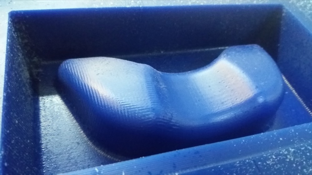
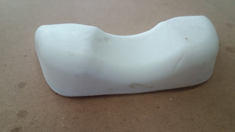
Finished piece:
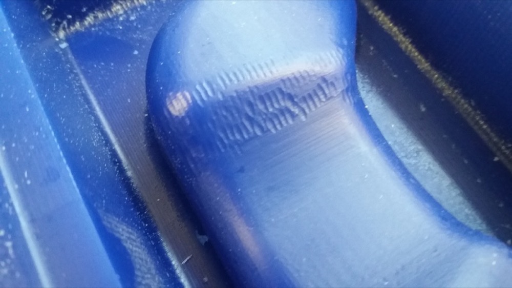
The rezeroing must not have been perfect, since I had this kind of artifacts:
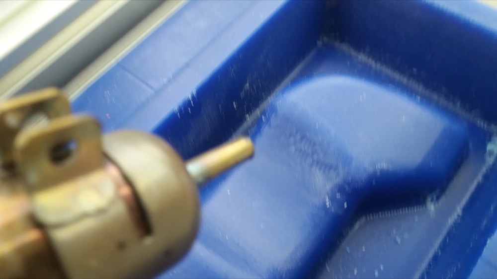
I tried to use the heat gun to correct these defaults and remove the tiny ships of wax:
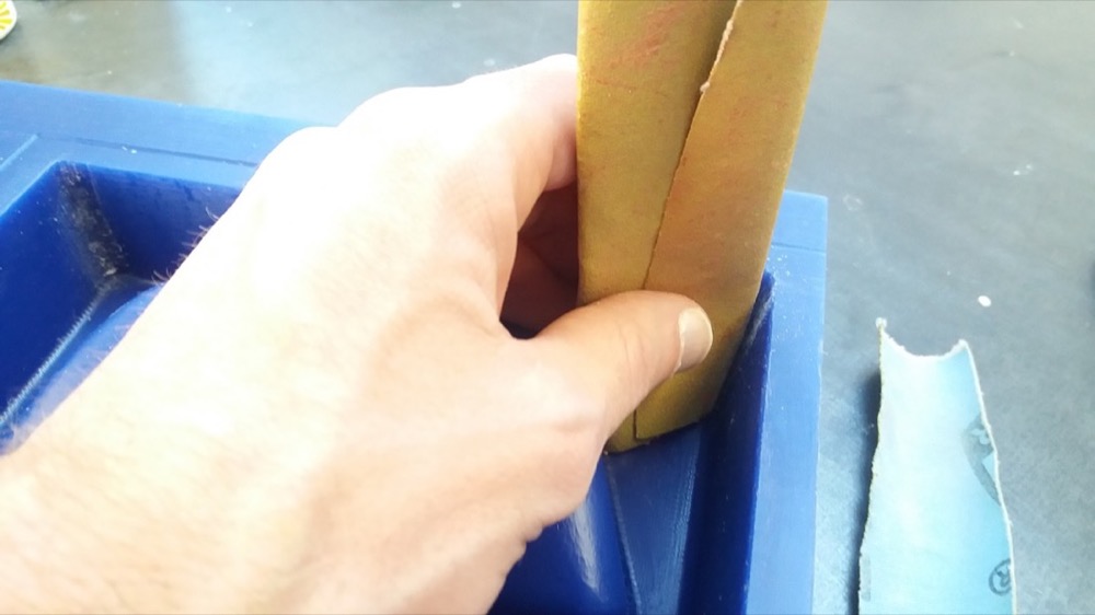
I also used sand paper to remove the bumps in the corners to allow demoulding:
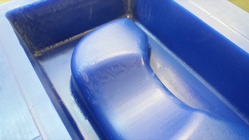
It didn’t solve everything but the defaults were less visible:
Moulding the top part
Since I used a smaller wax block, I didn’t have place for clamps. I had to get creative:
Rough cut in progress:
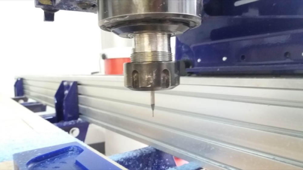
To carve the buttons and the letters, I used a 1/32 inch bit:
I made an air cut to make sure that everything was fine:
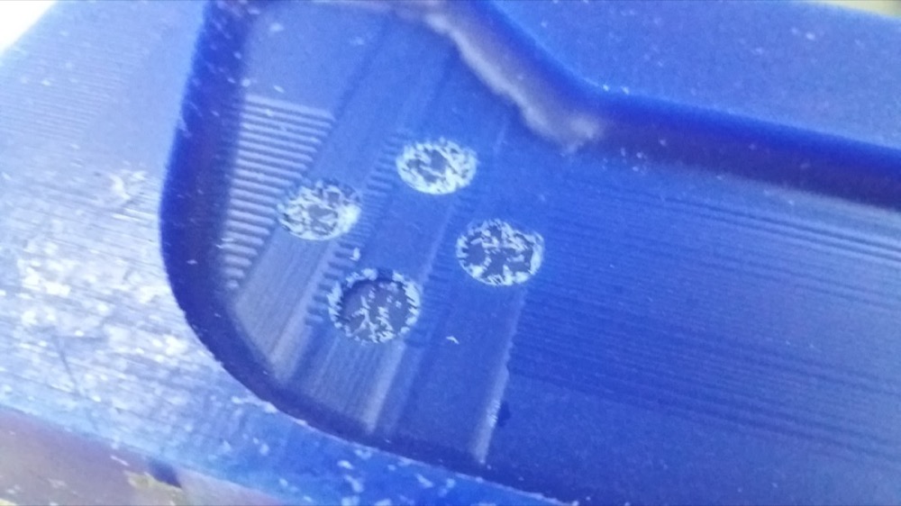
The buttons came out sharp and I was satisfied with this result:
However I had some problem with my second finish cut. I used the same strategy as the one that worked for the bottom mold:
- Rough cut
- Finish cut with two passes at 90° (along x and along y) with a stepover of 11%
- Finish cut with only one pass but a stepover of 2%
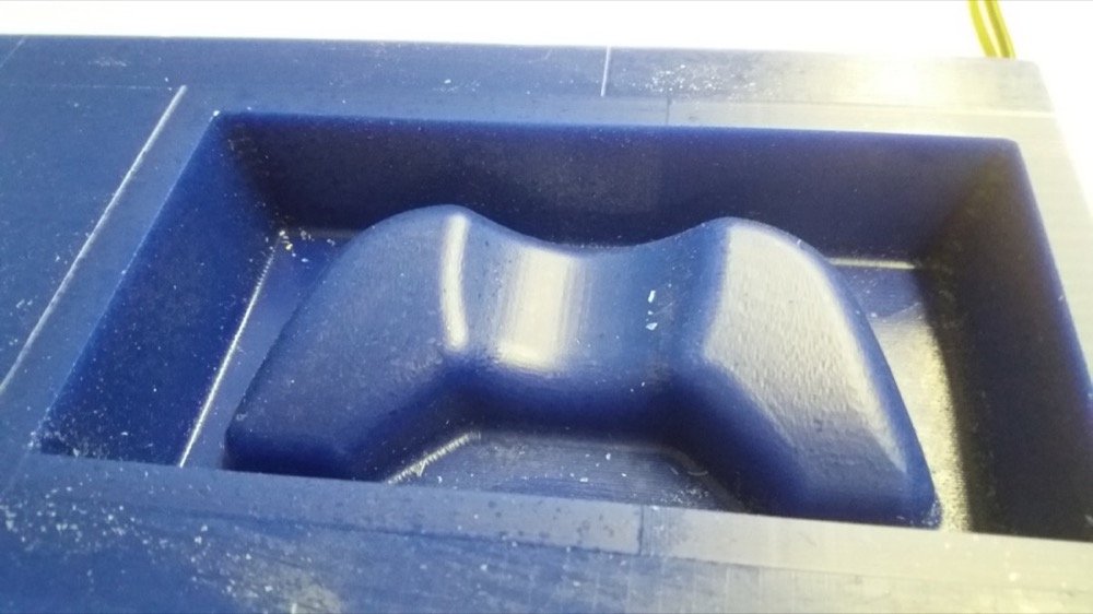
This time, it resulted in some strange artifact:
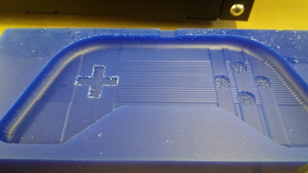
The final cut was made along the smaller axis. Where the buttons are, the finish is very smooth, but along the tool paths where there are no buttons, the tool seems to have cut much higher than what it should have…
Making the PCB
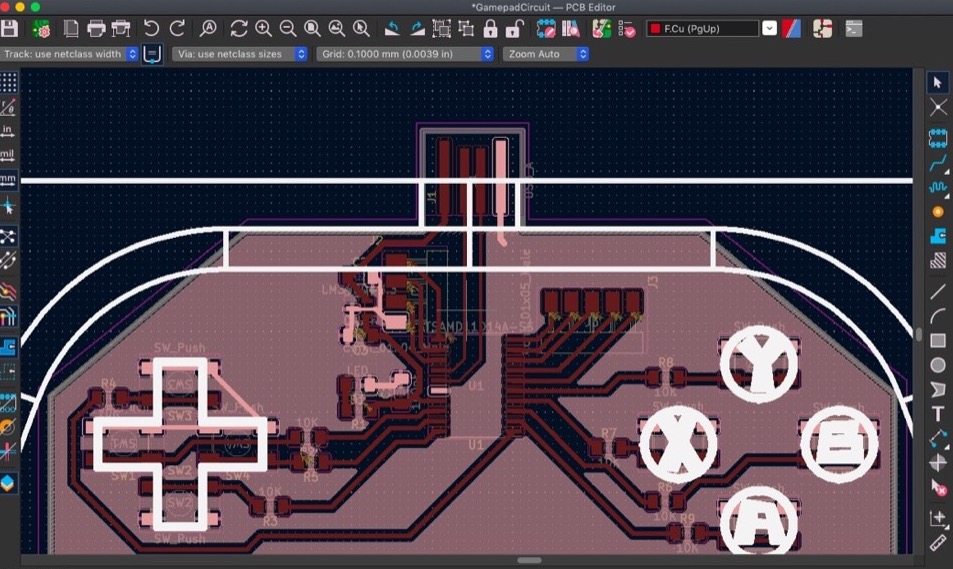
I imported the gamepad design as svg in order to position the buttons correctly on the PCB:
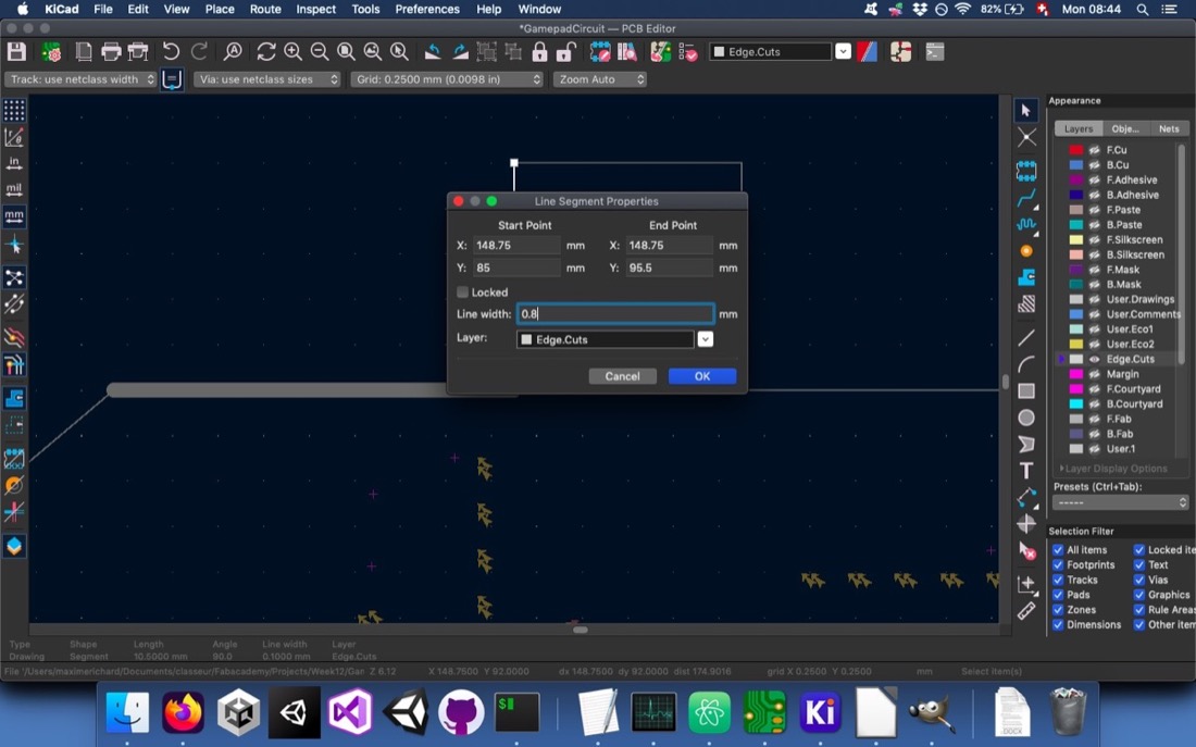
Since my edge cut lines were too narrow the previous weeks, I remembered to set them at least as wide as the cutting tool, this time:
Even though I set the gap width at 0.4mm, I still had some problems when generating the toolpath:
I widened the minimum gap and these issues were fixed:
Since I had many problems the previous weeks with the cutting depth which wasn’t deep enough, I set it to 0.12mm right away:
With the default parameters for the edge cut, I didn’t get a good gcode file:
So I decreased the tool width and the gcode was correct:
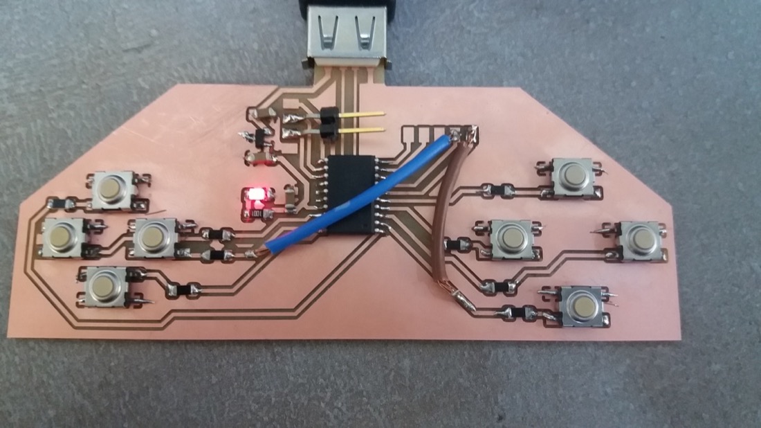
I could then cut my PCB:
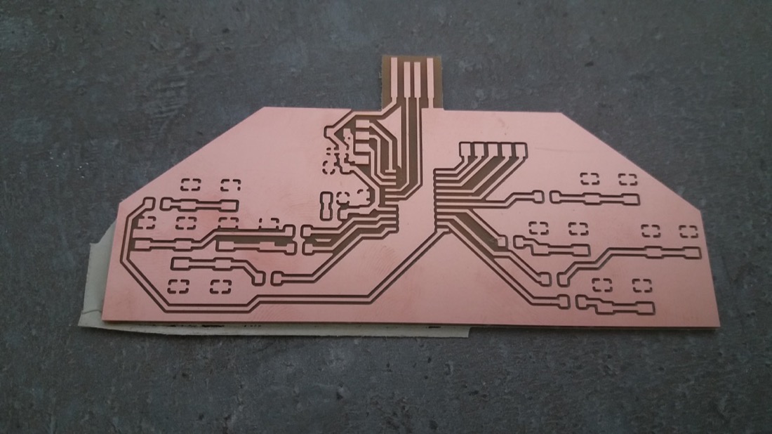
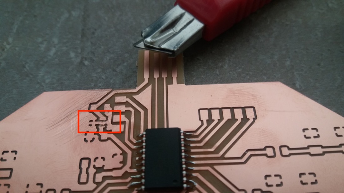
When visualizing the gcode, I didn’t notice that I still missed some cuts, so I made them with a cutter:
I felt more comfortable and faster for soldering, this time.
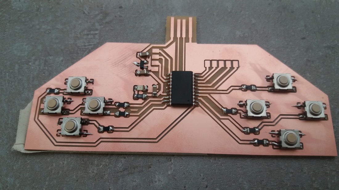
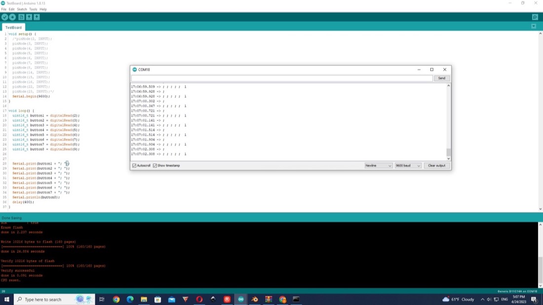
After programming the board, I wrote a short code in order to test the buttons. At first, only one button seemed to work:
After few trials, I got 5 out of 8 buttons to work:
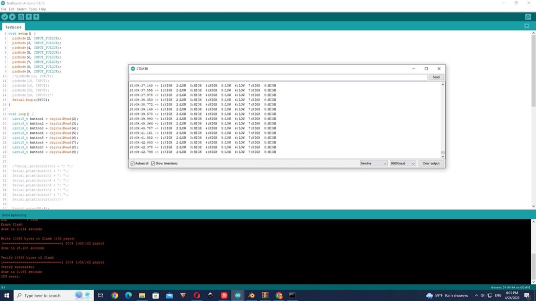
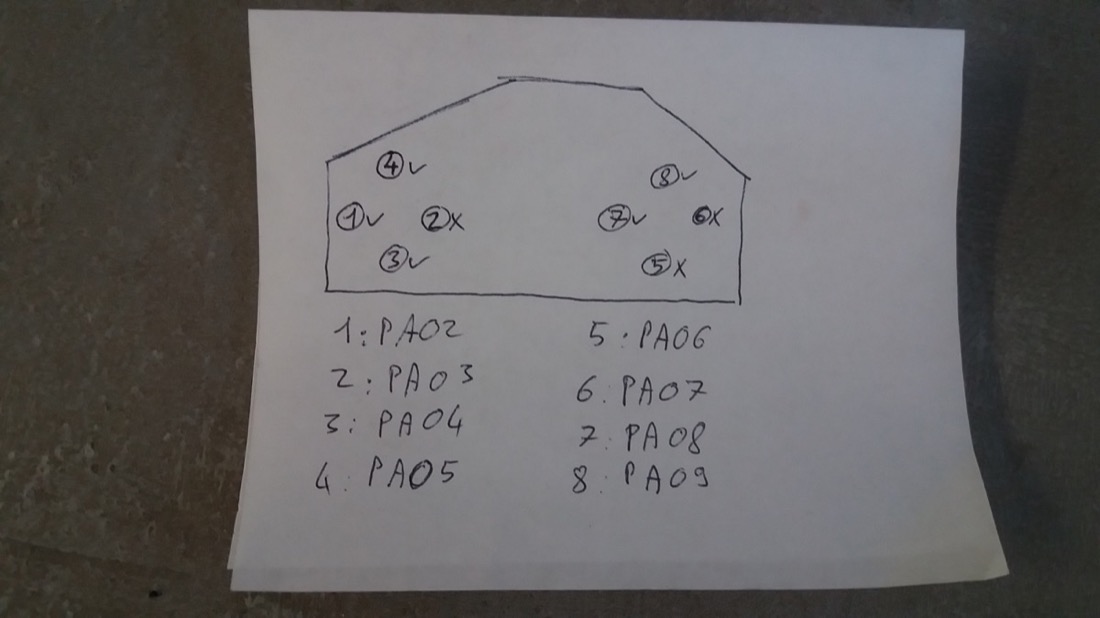
I also checked the other pins by setting them as output and measuring the voltage on each of them. 2 out of 5 were working. Using some wires, I connected the 2 working with 2 of the buttons to get 7 out of the 8 buttons:
Casting
Casting the bottom part
For the casting Ashot Margaryan, a former student of the Fabacademy, helped me a lot! He is working in a metal casting factory and his insights were very helpful.
I chose to use plaster to cast the negative mold for the bottom part:
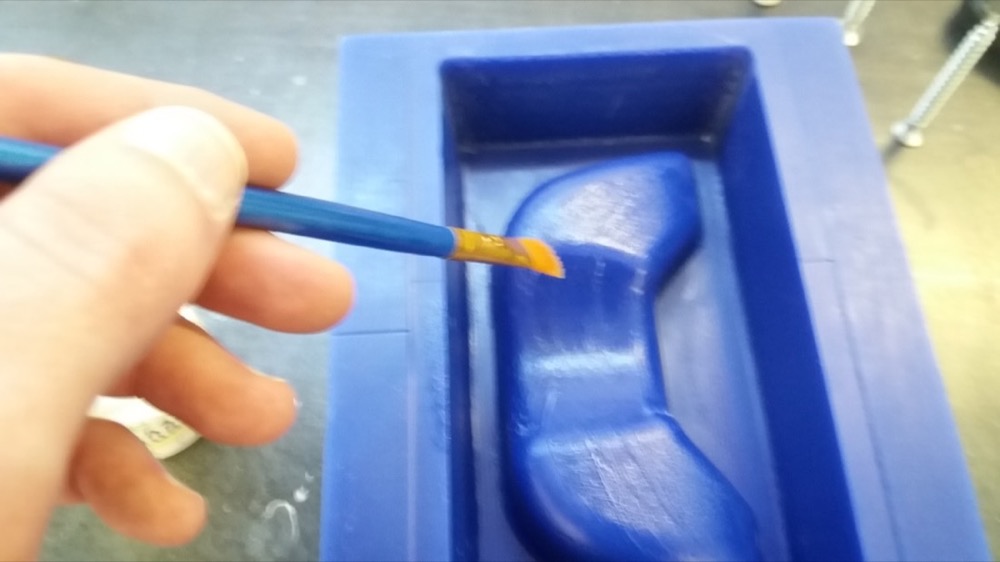
In order to make the demoulding easier, I used vaseline to lubricate the mold:
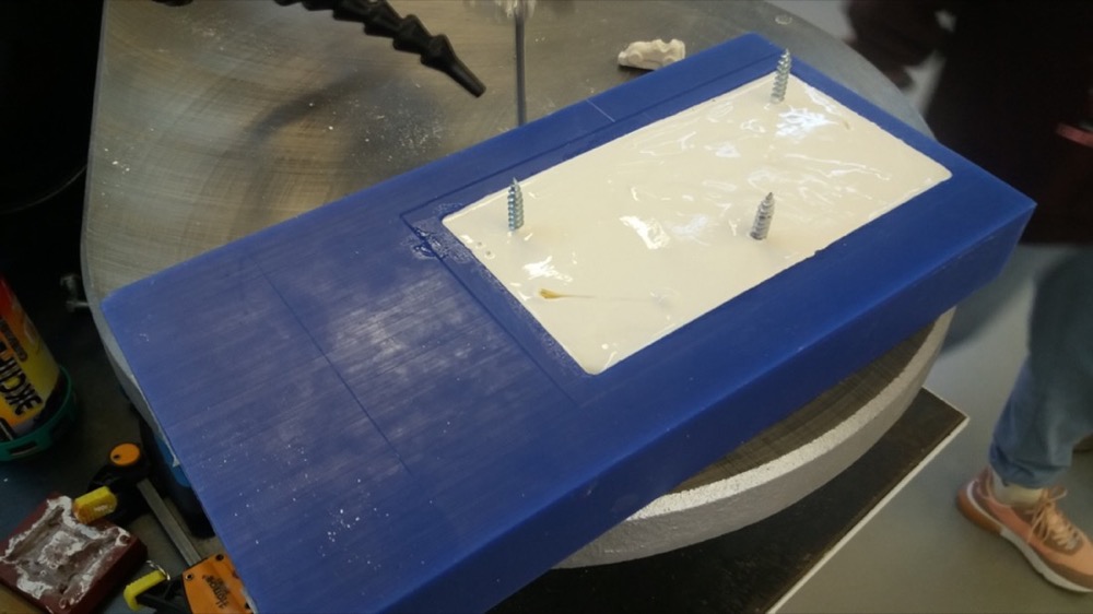
put some screws to pull on the plaster part
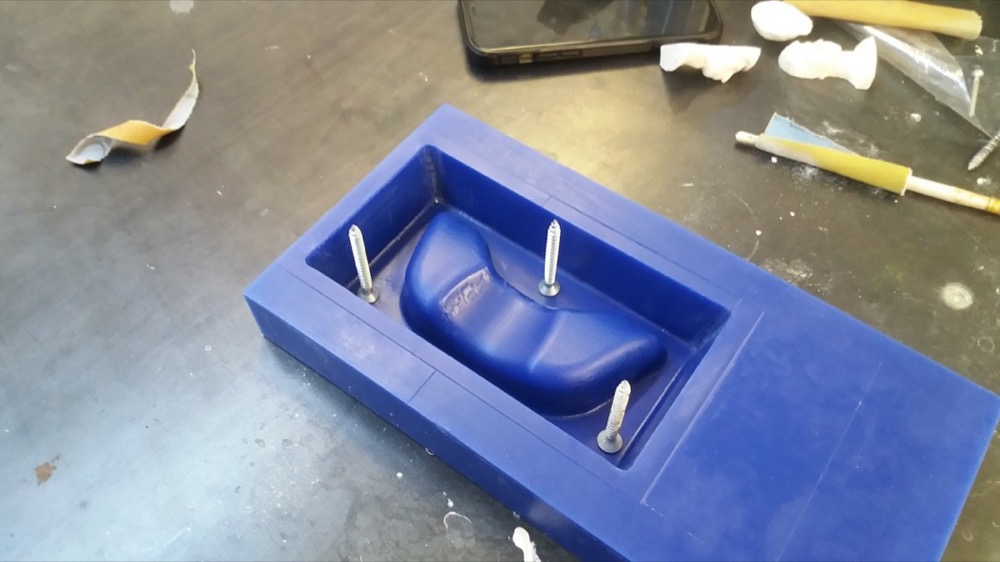
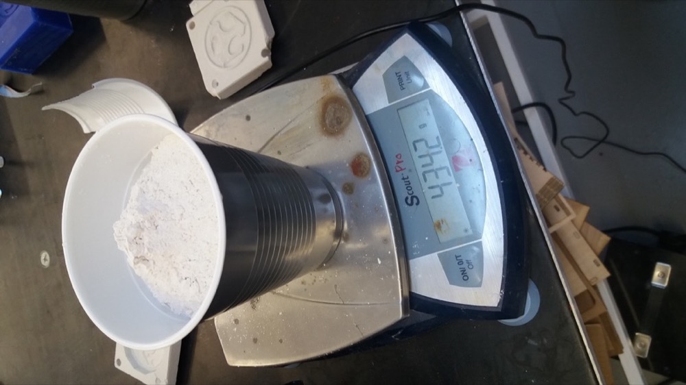
Since I forgot to measure the volume of the mould with water before putting the vaseline, I used a different technique: I measured the width, length and depth of the mold to obtain a max value for the volume. I realised that I need almost a full glass of plaster:
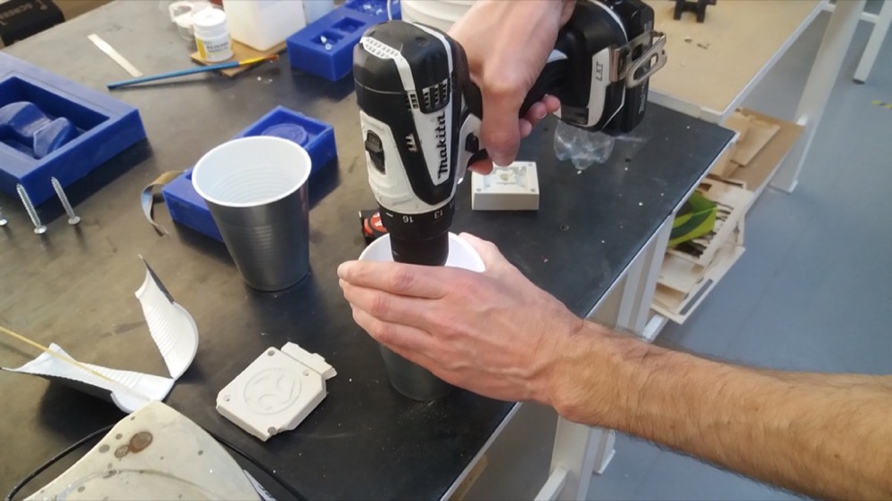
To mix the plaster, we used a powertool:
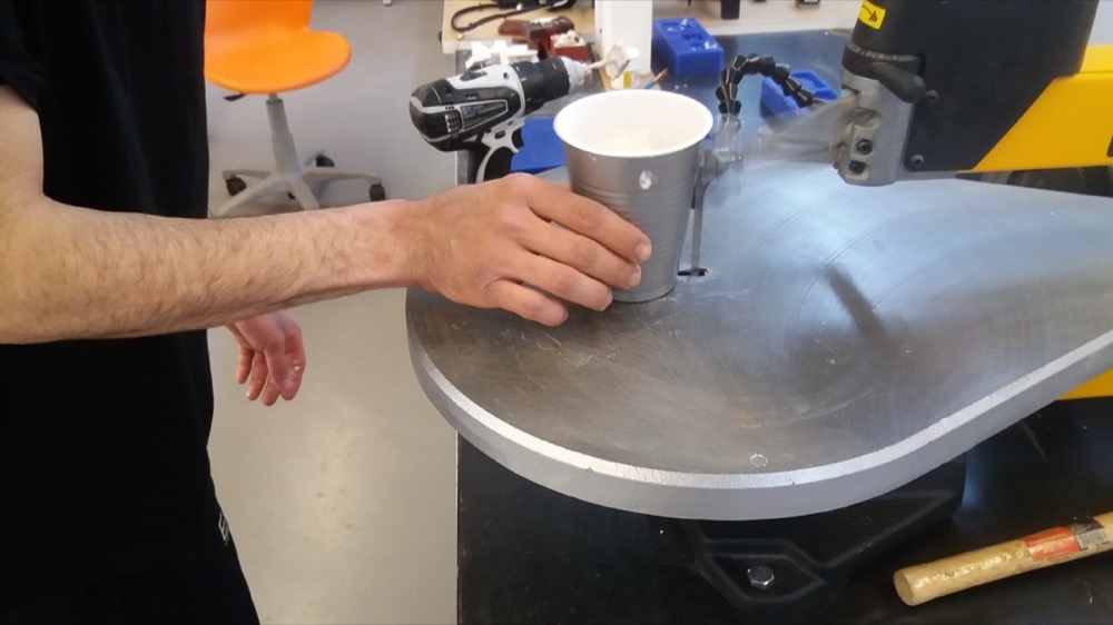
To remove the bubbles trapped inside, we used the vibrations created by a saw:
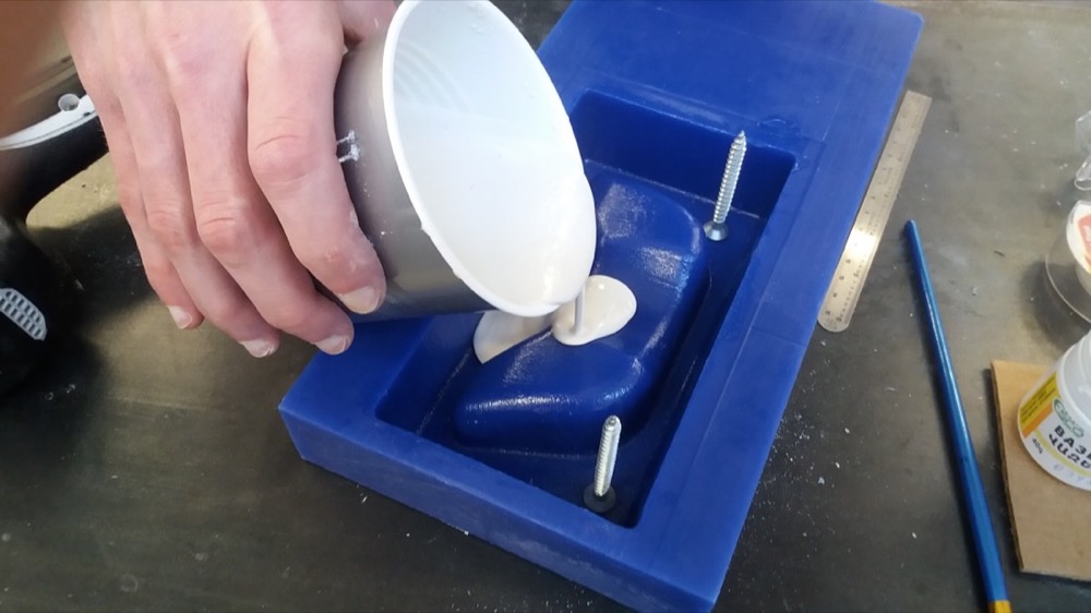
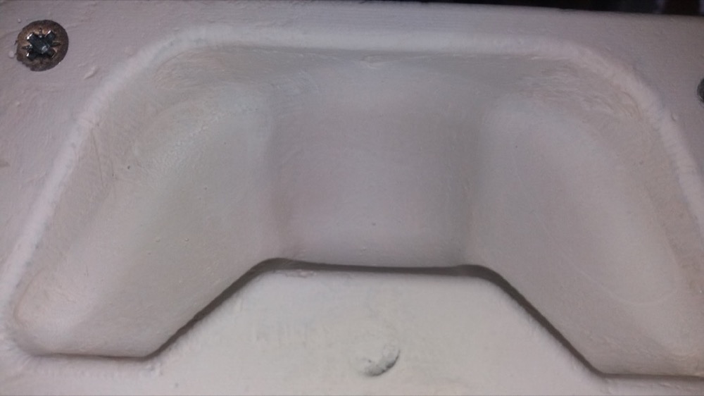
We then poured the plaster into the mould:
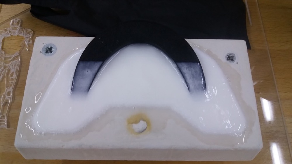
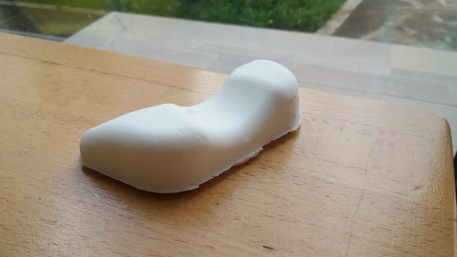
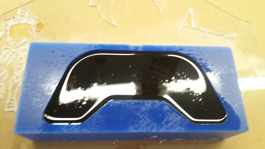
After about 15-30 minutes, I could remove the part from the wax mould. The result wasn’t perfect, but I didn’t expect too much, working with plaster:
I left it dry for about one day and then started to prepare for casting with Smoothcast 305 with all necessary safety equipment. I also opened the window:
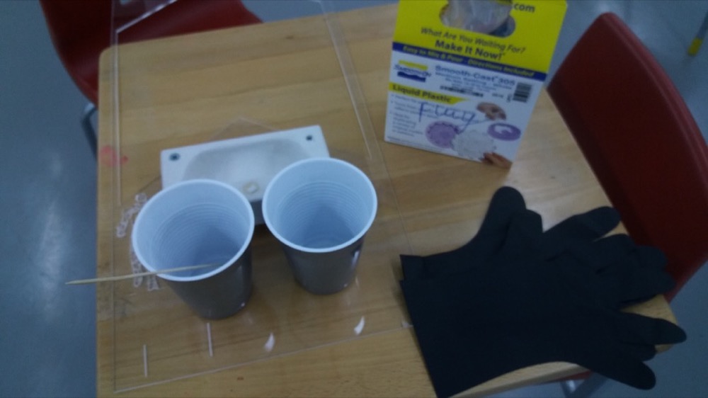
I used a thin round stick to mix because it doesn’t incorporate air as much as a flat one. I stirred horizontally, with no vertical movement.
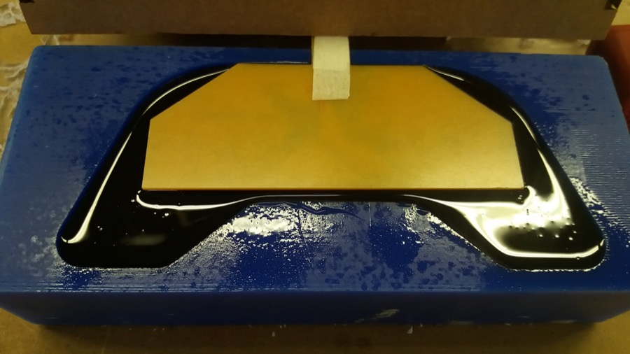
In order to pull the plastic out of the mold, I 3D printed a handle that I sticked inside the mould after pouring the mixture. Unfortunately, it fell down before the polymer solidified:
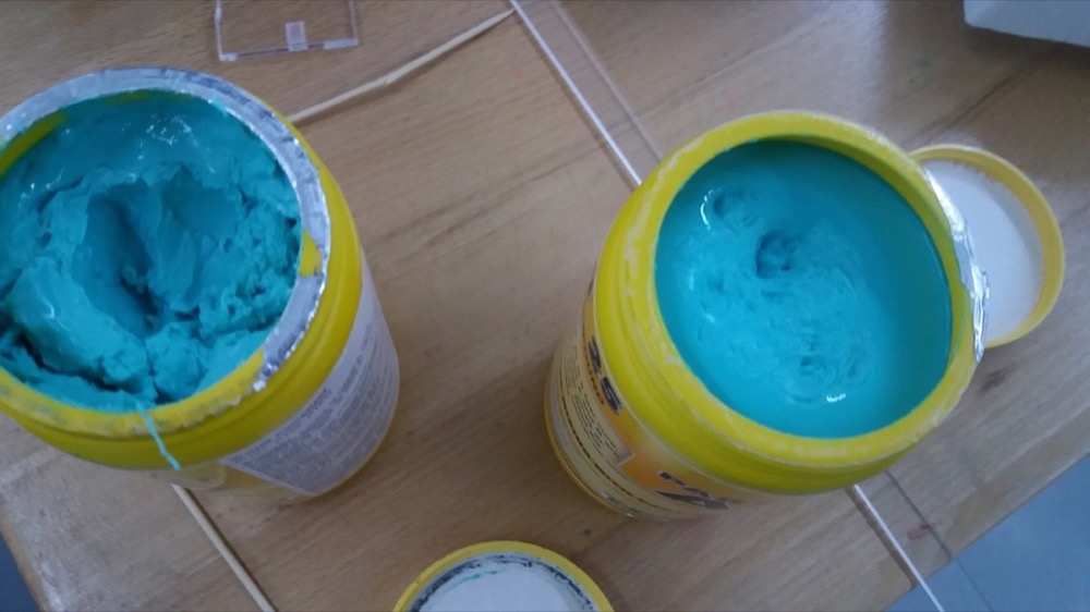
On the same day, I wanted to also cast the top part, but all the oomoo 25 left were not usable. The already open part A was solid (left on the picture), but when I opened a new container of part A (right on the picture), it was also solid:
Demoulding the bottom part
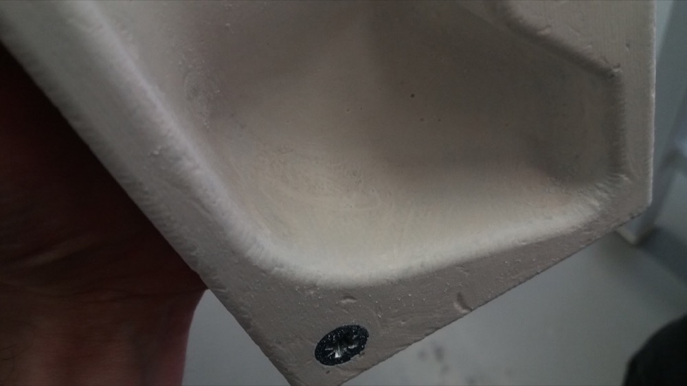
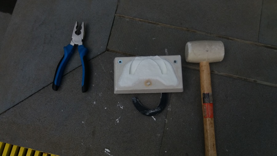
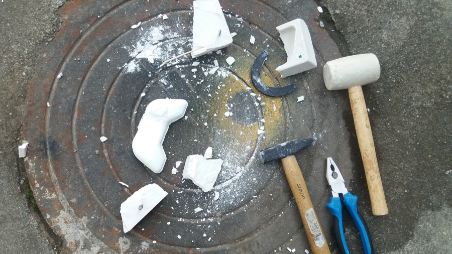
As expected, I didn’t manage to remove the plastic part from the plaster mould just by pulling on it and hitting the mould. I resolved to break the mould to take out the part:
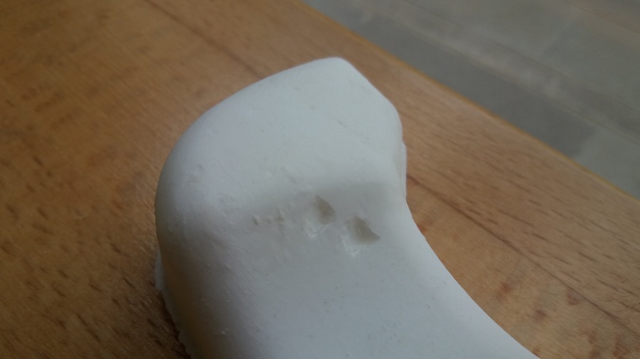
I had poured too much misture into the mould. The part would have had a smoother top surface if I had poured less:
Unfortunately, when removing the mould, I hit the part twice with hammer:
I tried to use sandpaper to smooth some of the defects, but manipulating the plastic in this way colored it in some places. I didn’t expect this and was a bit disappointed:
Casting the top part
Before casting, I measured the volume of the mould with water:
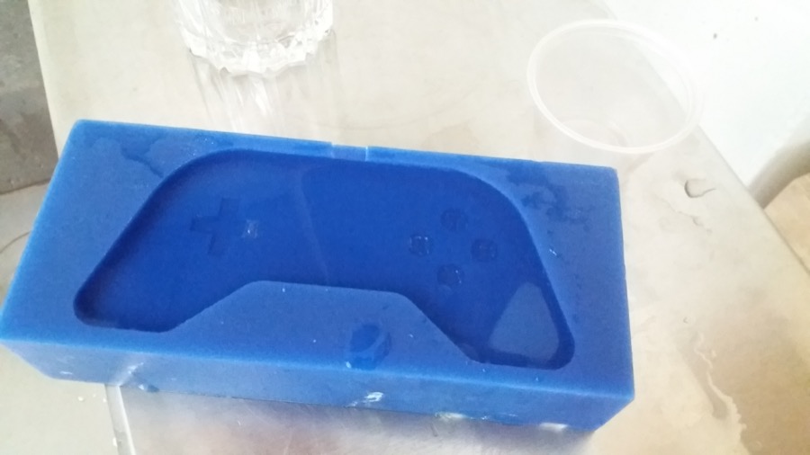
I used a silicone lubricant to facilitate demoulding:

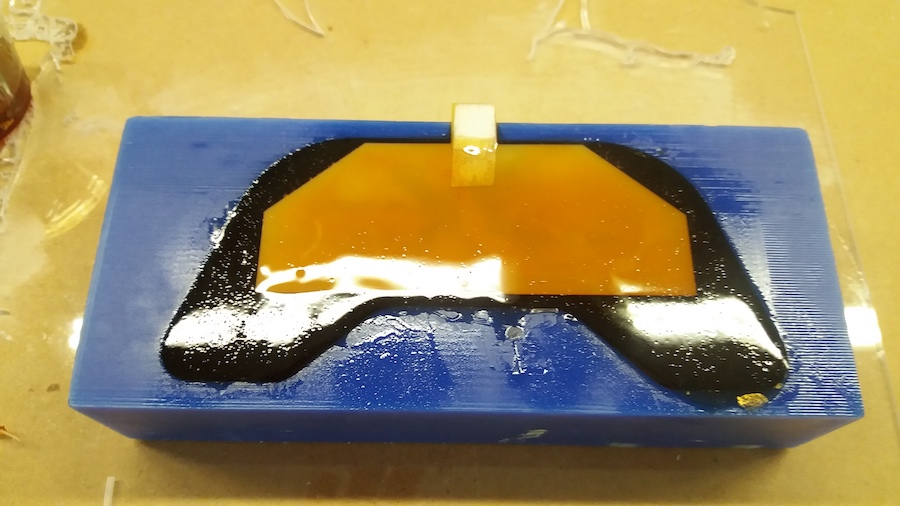
I didn’t fill it to the top, because I needed to add the PCB:
After adding the PCB, I realized that I needed to add a bit of mixture:
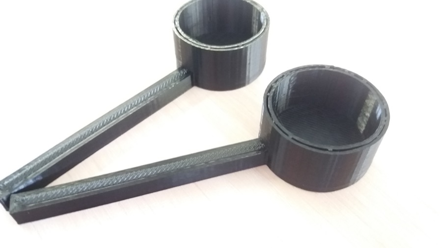
Since I needed a very small quantity and that the viscosity of part A makes it hard to pour, I 3D printed some small spoons of a bit more than 5ml:
I poured until the PCB was fully covered:
The demoulding went well and the result was quite smooth. However, I realized that I had made a very stupid mistake: the left and right buttons were swapped, I forgot that when making a negative mould, I needed to mirror it horizontally!
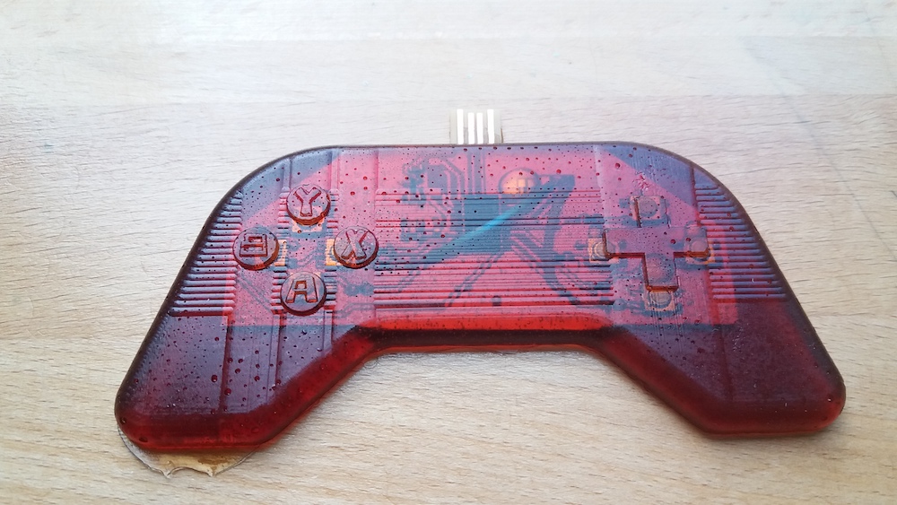
There were many bubbles but I intentionally stirred the mixture in order to incorporate a lot of air to obtain a visual effect on the gamepad.
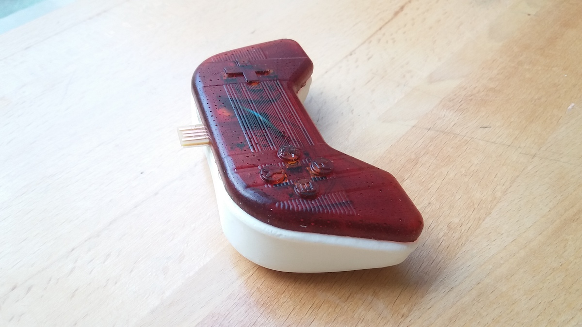
And here is the whole gamepad:
Testing the gamepad
When plugging my PCB, I was satisfied to see that the buttons that were previously working were still working:
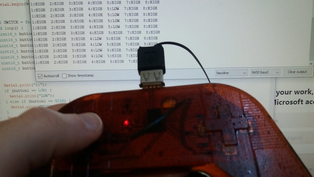
I didn’t manage to make it work as a USB peripheral this week, but I’m thinking to try to continue this project next week, since it’s some kind of network communication between the gamepad and the computer.
Group assignment
Here is the link to our group assignment.
We were lucky to have Ashot Margaryan, a former student of the Fabacademy, in the lab for a few days. He is experienced with metal casting.
I was surprised to see that it was possible to cast aluminium with the help of a simple high temperature oven and plaster molds. I would however still be afraid of wet plaster. Indeed, this could cause a very fast gasification of water and cause some high temperature liquid to squirt.
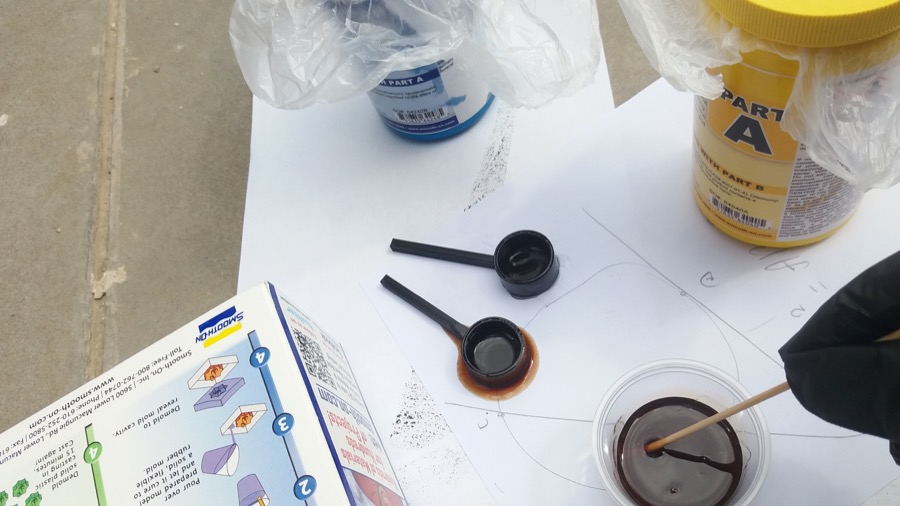
When casting with the rubber, we didn’t mix enough and some of our results were not good. This is probably due to the small stick we used for the big quantity we were making. I used the same process for small quantities during my individual assignment and didn’t have any problem. So in the future, I will need to be careful when making bigger quantities that the mixture is homogeneous.
Conclusion
This week was the busiest one for me. I was in the lab everyday for many hours. But in the end, I was satisfied to have a working device, even though there were many things that could have been improved.
The most frustrating part of the week was the g code generation. I was bugged down by the scale difference between the rough cut and finish cut files, even though it would have worked if I would have tried.
The mirrored buttons was a bitter mistake, because I only realized it at the end, when the product was almost finished.
I think that the gamepad looks not too bad, even though the white plastic is damaged. However, it is very hard to use, as the buttons need a lot of force to be pressed. This could be maybe mitigated by having a thinner layer of rubber on top of the PCB.
Files
ZIP folder for the files of this week