Week 2: Computer-aided design
✓ model (raster, vector, 2D, 3D, render, animate, simulate, …) a possible final project
✓ compress your images and videos
✓ post a description with your design files on your class page
2D Vector Design
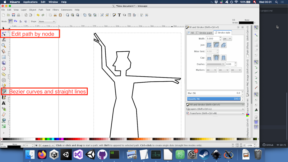
First, I used Inkscape to draw the silhouette of a character of my diorama. Vector drawing is using mathematical formulas to represent lines. It has the advantages of being perfectly scalable. Furthemore, the default saving format, .svg, can be directly imported into a 3D parametric design software to then create a solid.
I used the tool to draw straight lines and Bézier curves in order to sketch the shape of a woman dancing. Then, I used the tool to edit the path by node. The path is represented by the lines I just drew and the nodes are the individual points that make up this path:
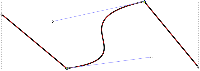
If my understanding is correct, the Bézier curves tools enables to draw a spline, which is a mathematical function defined piece by piece by polynomials, which, in this case, are Bézier curves. These “pieces” are defined by two nodes and maximum two handles. The order of a polynomial defined by four control points is three. In the example below, we have therefore one cubic Bézier curve and two linear Bézier curves:
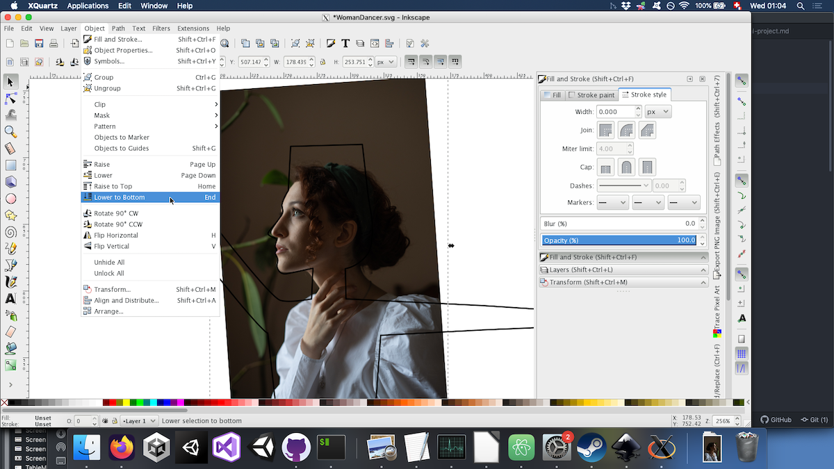
In order to refine my drawing, I traced a face from an image free of right found on Pexels. In order to trace upon it, I first had to send the image below my path:
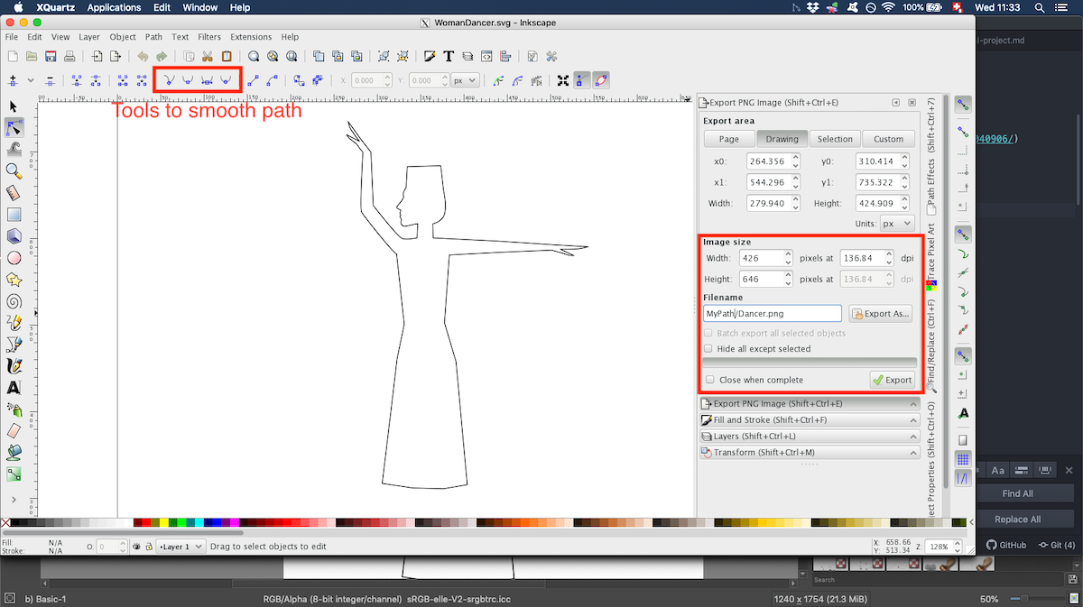
After smoothing some nodes and refining the shape, I exported the image as a .png.
Raster 2D design
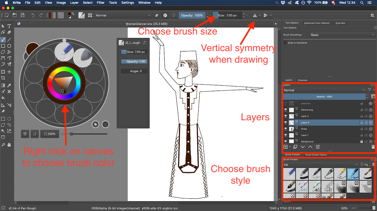
Instead of representing images with mathematical functions like in vector design, raster graphics represent images with a matrix of pixels. The software I chose is Krita, since it is free and open source and has a set of brushes that I like.
Since I will mostly use wood, it should be possible to burn some graphics with the laser. First, I imported the .png file of the silhouette made with Inkscape by dragging it onto the canvas. I could then draw on other layers inside this silhouette.I used the vertical symmetry when drawing the patterns:
FreeCAD tutorials
I have a small experience using the 2D design softwares Krita and GIMP for raster 2D design and Inkscape for vector design. I’m also sometimes using Blender, so I will use this program for 3D rendering. However, I’ve never used any 3D parametric design software before. Since FreeCAD was the software shown more extensively in the lecture, I decided to explore this one. Besides the lecture that already presented many features of this software, I started by watching a few youtube tutorials:
- A short tutorial on how to make a phone holder
- A longer beginner tutorial which goes over more functionalities
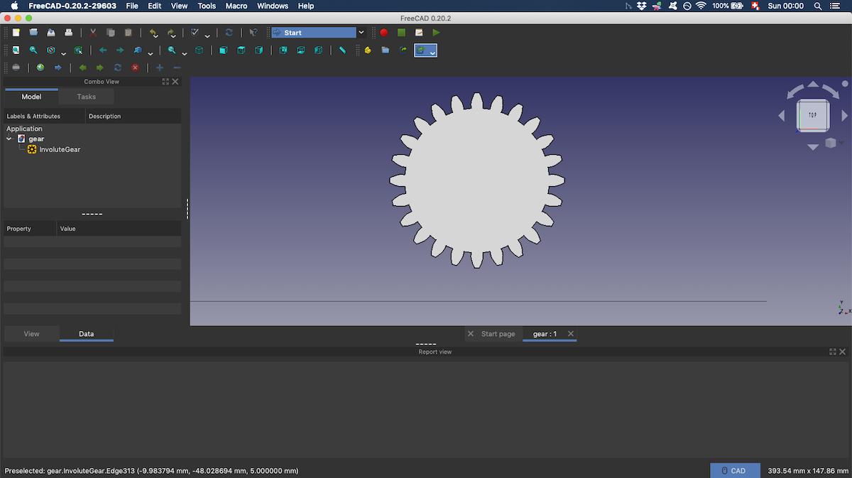
Since my final project will probably need some gears, I also followed a tutorial on how to make gears. I struggled a bit doing basic tasks. Since I used the Freecad Gear add on, creating a basic gear wasn’t difficult. But when I tried to add a circle in a sketch in order to make a simple hole through the gear, I didn’t manage. Indeed, I forgot to create a body before adding the gear. So I just erased everything and started again.
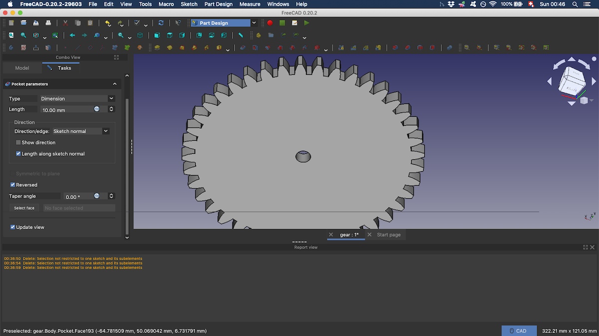
I also encountered difficulties when making the hole using the pocket function. All the parameters seemed correct, but no hole nore pocket would show in the viewport. After some trial and error, I understood that I had drawn my circle on the wrong face of the gear. A quick fix was to tick the reversed box in order to “dig backwards”.
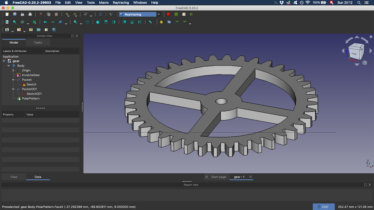
Eventually, I was able to model something that would resemble a gear:
Modeling the final project
In the diorama that I want to make as a final project, the main part will be a church inspired by armenian architecture. The towers are cylindrical on armenian churches and I anticipate that this will be the harder part to build.
Parametrizing some dimensions
Since I am not sure what will be the final scale of my project, it seemed important to be able to quickly change the size of the different parts of the model. Indeed, the measurments that I first chose will probably be anyway so small:
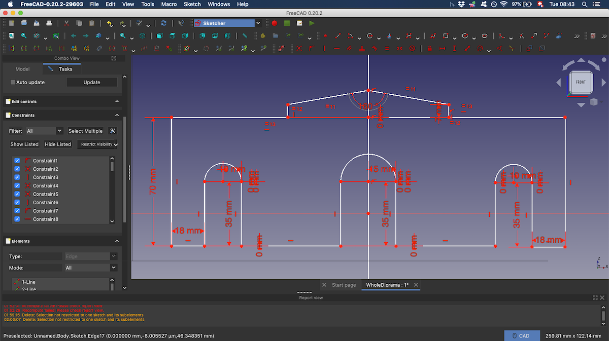
FreeCAD enables to parametrize dimensions through a spreadsheet, so I wanted to learn how to do this. I first watched a tutorial on parametric modeling and then started to implement it for my model:
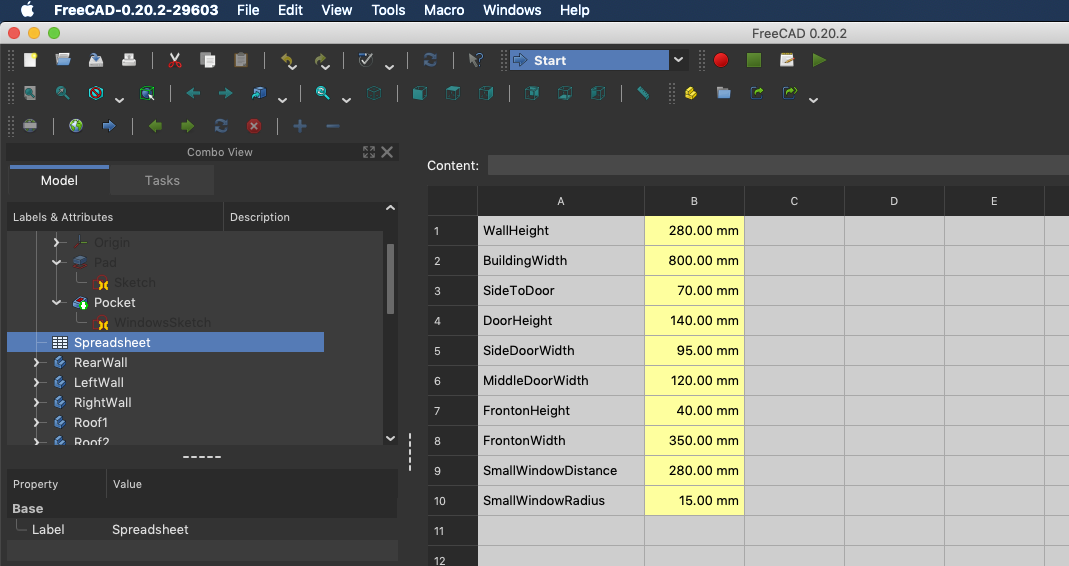
NOTE TO SELF
After changing a parameter in the spreadsheet, it doesn’t always update the body. In order to do so, right click on the body and select Recompute object.
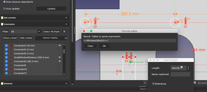
FAILURE
I struggled to refer another constraint from the same sketch. When trying to look for this reference in the formula field for a constraint, I couldn’t find the name of the other constraint.
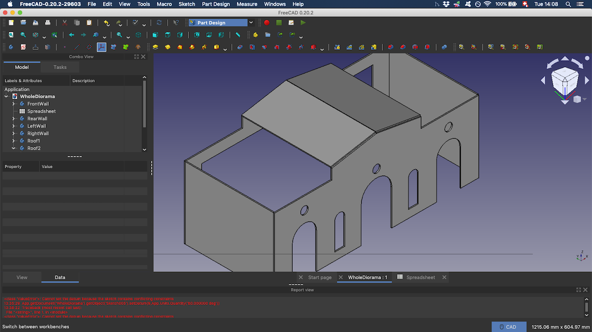
I eventually managed to model a first draft of the walls and part of the roof:
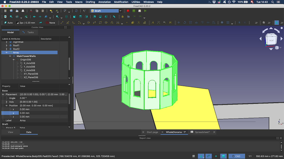
The round tower
Since I want to make most of this project by laser cutting wood, the tower won’t be perfectly round. I will approximate the circle by a polygon. I therefore started by sketching a piece of the wall with a window. Then, following a tutorial, I used the array tool inside the Draft workbench. It is possible to obtain a cylindre like shape by changing the “array type” from ortho to polar:
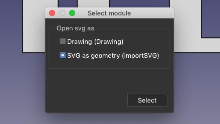
Importing the character drawn in Inkscape
I first imported the .svg file from the File dropdown menu as geometry:
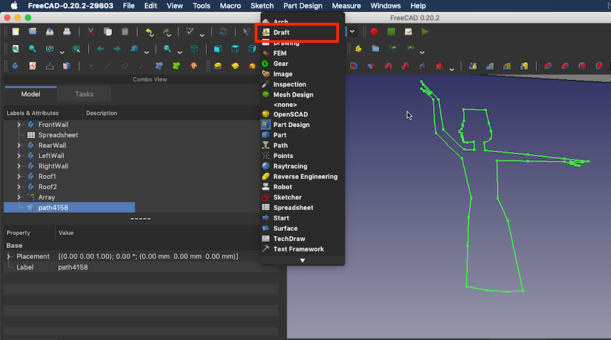
I then switched to Draft workbench:
In order to create a solid, I converted the path to sketch:
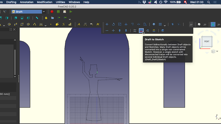
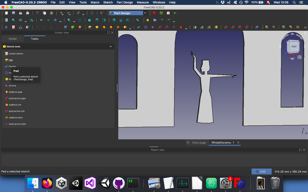
Once I had the sketch, it was possible to use the Pad tool in order to turn it into a solid.
Conclusion
The 3D CAD part of this week was more challenging for me since I had a bit of experience with some 2D softwares. Even though I made a very simple design, I had to look for learning resources at every step of the way.
Files of the week
STL file of the diorama in the current state