Week 5: 3D Scanning and printing
✓ Design and 3D print an object that could not be made subtractively
✓ 3D scan an object
✓ test the design rules for your 3D printer(s)
Group assignment
Since the Fabacademy students from last year already tested the printing rules for our printers, we decided to compare our two printers and to test another feature. The details are available on our group page.
MakerBot Replicator 2 VS Creality Ender 3
| Feature | MakerBot Replicator 2 | Creality Ender 3 |
|---|---|---|
| Build plate Material | Acrylic, covered with scotch tape | Coated aluminium |
| Removable build plate | yes | no |
| Build plate heating | no | yes |
| Build plate adherence | High adherence. Most models don’t require a raft | Low adherence. Most models require a raft |
| Usable printing materials | Only PLA | PlA and ABS |
| Extruder nozzle | 0.4 mm static nozzle | switchable nozzle |
To demonstrate the necessity of a raft on the Ender, we tried to print without it. The printing process fails before the end when the printed part shifts on the build plate. It is easy to mitigate this issue by adding a raft (for example. Other supports, like a brim, would also work). The waste of plastic is not too high (1.7g in our example).
On the MakerBot, a raft is most of the time not necessary. Indeed, some kind of scotch tape covers the build plate and dramatically increases the adherence.
Mesh accuracy VS print quality
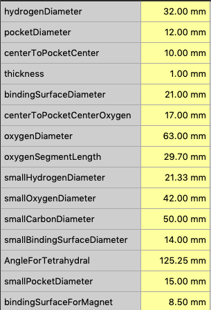
To generate G-code, the slicer needs to first import an .stl file. In order to do this, we need to turn our model made in FreeCAD into a mesh made of triangles. In the Mesh Design workbench, we can select “Create mesh from shape”. During this process, when choosing the “standard” meshing options, we can adjust two parameters: the surface deviation and the angular deviation.
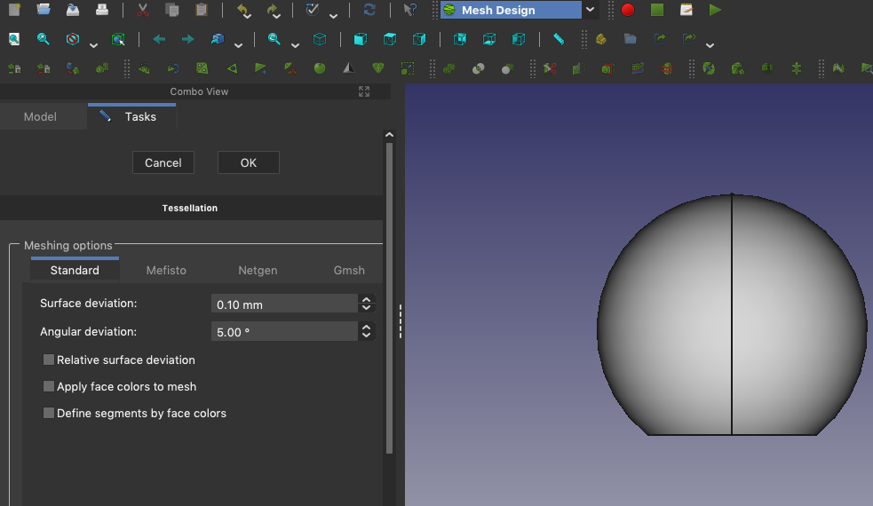
The test model we used was a sphere of 18mm diameter with a truncated base.
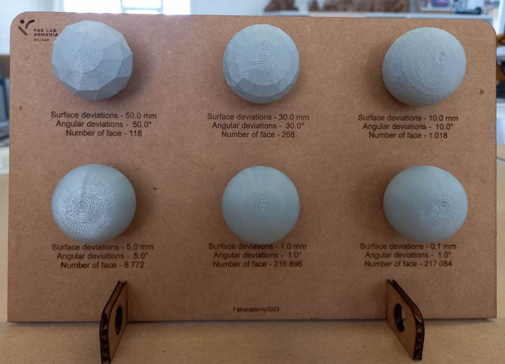
Here are the results of our experiment:
| Mesh 1 | Mesh 2 | Mesh 3 | Mesh 4 | Mesh 5 | Mesh 6 | |
|---|---|---|---|---|---|---|
| Surface deviation [mm] | 50.0 | 30.0 | 10.0 | 5.0 | 1.0 | 0.1 |
| Angular deviation [°] | 50.0 | 30.0 | 10.0 | 5.0 | 1.0 | 1.0 |
| STL file size [kB] | 6 | 14 | 50 | 429 | 10 591 | 10 600 |
| Printed weight [g] | 6.32 | 6.75 | 6.92 | 6.93 | 6.94 | 6.94 |
| Printing time [min] | 27 | 28 | 29 | 29 | 29 | 29 |
We can notice that the differences between the last two models are small. The results are indeed not really distinguishable. The sweet spot for this type of shape lays probably between Mesh 4 and Mesh 5. We can see that the difference in file size are huge between these two meshes.
3D scanning
Since we don’t have a 3D scanner in our Fablab, I used an app for smartphones: Kiri engine. It is possible to download up to three scans per week for free. It is based on a photogrammetry algorithm and strongly depends on the quality of the photos. Another important feature to take into consideration is how the scanned object reflects light. I found that “shiny” objects are very hard to scan through this method.
I first tried to scan a plant we had in the lab:
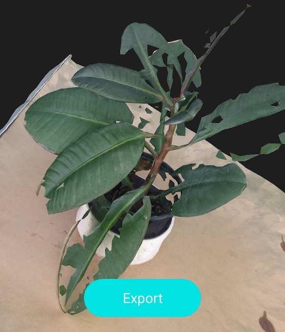
If some of the parts were of good quality, the leaves missed too many parts. I resolved to scan objects with less thin parts. I first tried to scan a small statue made of ceramics, but I got a hole at the spot where the statue was supposed to be:
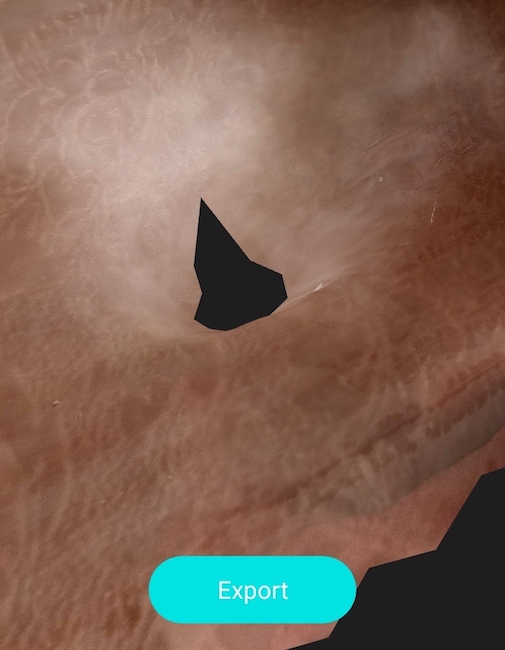
I have two hypothesis for why it failed: first, the material might have been too reflective. Second, the method to take pictures wasn’t appropriate. The app explains two methods to take picture around the object: either by turning around the object, or by staying in place and rotating the object. For this particular object, I rotated the object and this may have disturb the algorithm, since my background had a lot of texture, contrary to the example given in the app.
Eventually, I tried to scan some kind of toy:

The result was far from being perfect, but compared to my previous trials, it was much better:
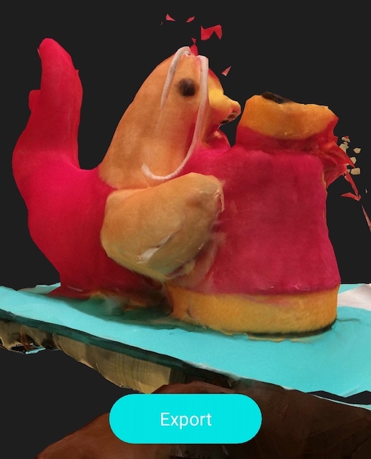
I then downloaded it in .stl format and imported it in Blender.
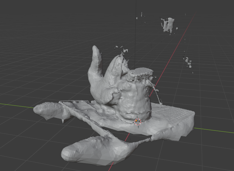
I then cleant it up a bit:
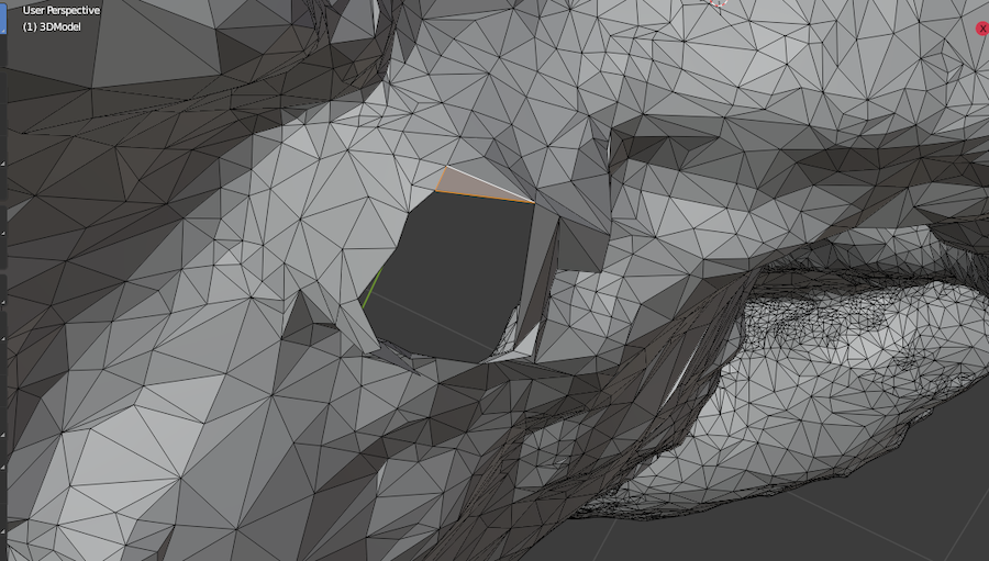
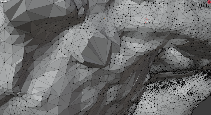
And here is the result:
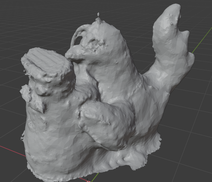
I think that the mesh is not accurate enough and too bumpy to yield a good 3D print, so I will leave this experiment as is.
Additional scan and photogrammetry setup
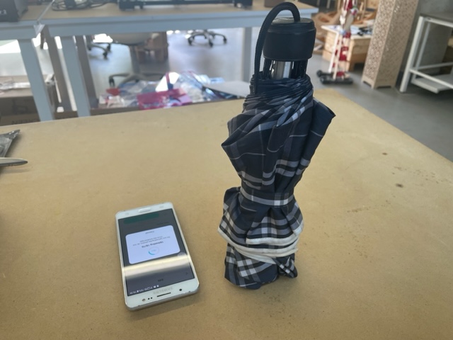
I later came back to 3D scanning and tried to scan an umbrella. The result was all right, except the small string, which was expected:
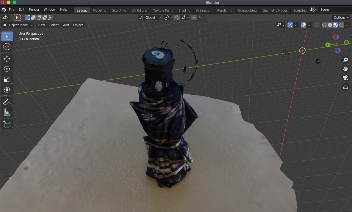
For 3D scanning using photogrammetry, I just put the object in a place with a good lighting all around and move around it to take pictures with my smartphone:
3D printing
I already made a very simple molecule building kit with cardboard during cutting week. I wanted to push this experiment by attempting to make a 3d printed kit. I took inspiration from the snatoms kit made by Derek Muller, the creator of the youtub channel Veritasium.
In the beginning, I struggled to understand how he managed to make the atoms stick together independently of the combination. Since magnets have permanent south and north pole, this seemed impossible to me. I then had the idea to let the magnets rotate inside a small pocket added inside the atoms for each binding spot. I later had the confirmation from a video that snatoms also uses this trick, but with spherical magnets.
This object could only be made with help of additive manufacturing, since it contains a pocket inside the outer shell.
Modeling
Hydrogen
Since I am still a beginner with FreeCAD, every new project comes with its challenges. This week, it was the first time I used the revolution tool and the mesh design workbench.
In order to keep it simple, I wanted to make only carbon, oxygen and hydrogen atoms with only single bonds. I started by sketching the hydrogen atom, since it was the simplest to make. I tried two different kinds of pockets:
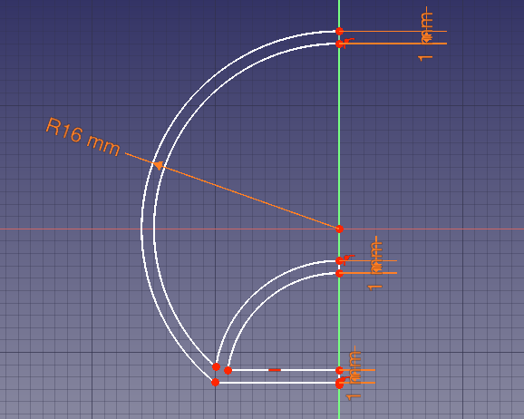
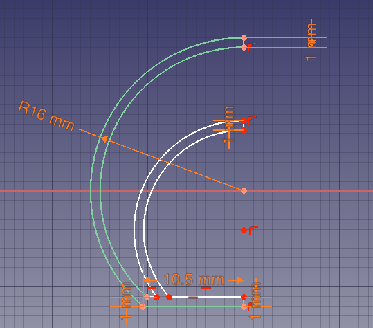
I kept the second one, since it allowed me later to shrink the size of the atom. I also parametrized some of the features to easily change them in case I needed to. But some of the parameters below were eventually not used:
Once the sketch done, I used the revolution tool from the Part Design workbench and then switched to the Mesh Design workbench. In this workbench, I used the Create mesh from shape tool. During this step, an algorithm will create a mesh of triangles following the shape of the model. It is possible to choose the accuracy of how the mesh will fit to the model. The higher the accuracy, the better the fit, but the more triangles will be used for the mesh and therefore the heavier it will be.
Carbon and Oxygen
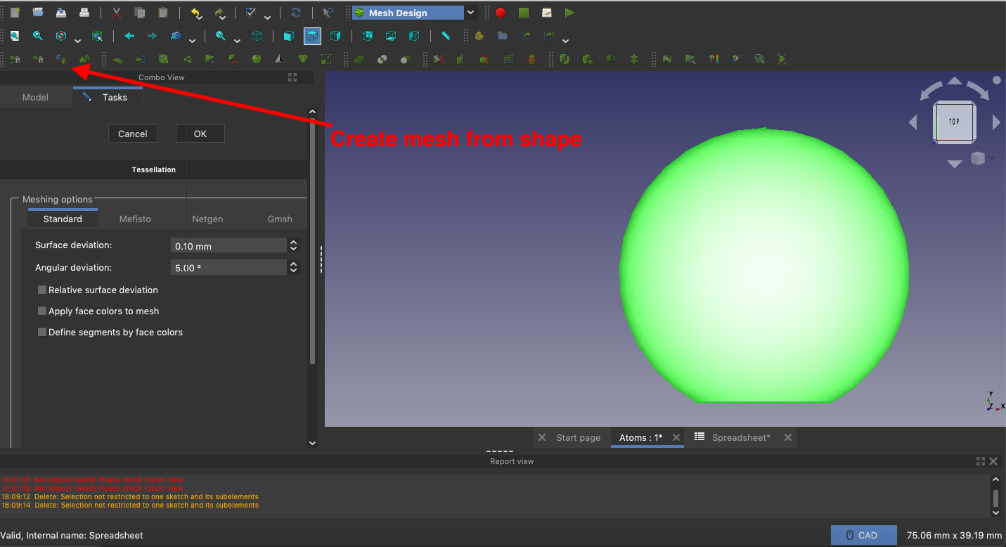
It was more complicated to make the carbon and oxygen atoms, because they have more than one binding site and they are not colinear. I had to make the pocket in another body and then use the boolean fuse tool to join them. I started by making a sphere with a thickness of 1mm. I then sketched the pockets and fused everything together. These are the pockets for the oxygen atom:
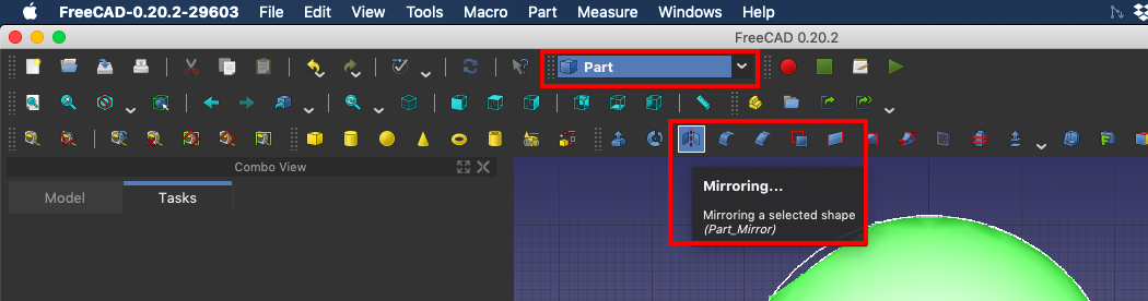
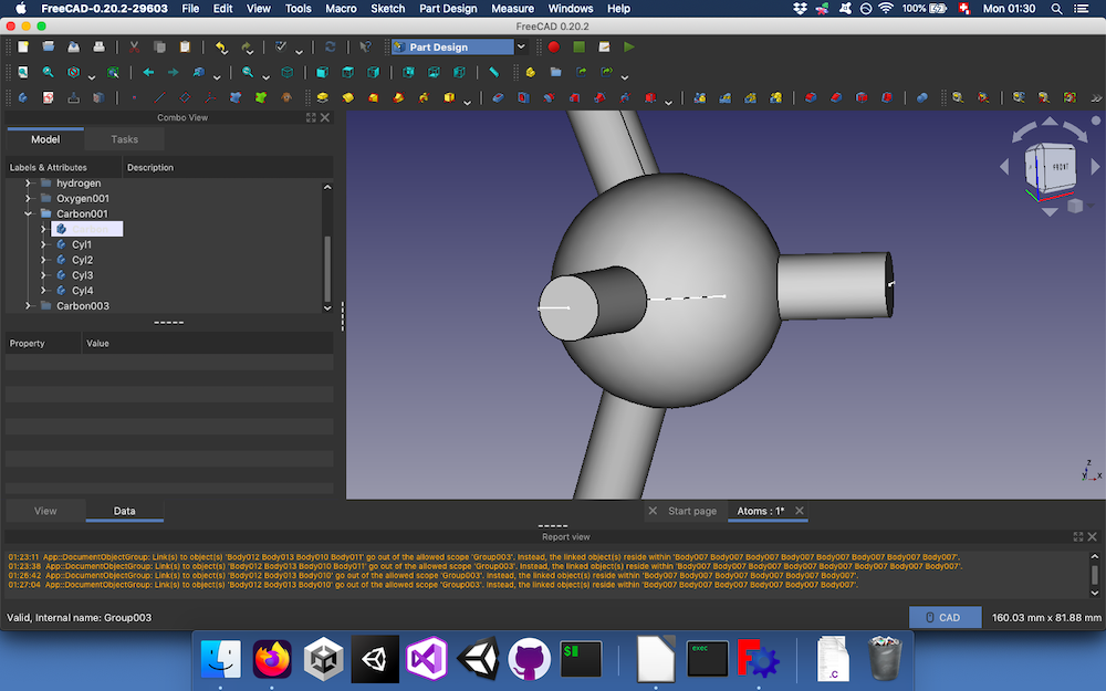
I then had to remove some part of the sphere in order to make the flat binding sites. I sketched a cylinder and let it revolve. I then had to do it for the other faces but struggled a lot. I wanted to mirror it using the Part workbench:
Unfortunately, when I tried to use the boolean cut with the mirrored bodies, it didn’t seem to work. After struggling some time without finding any solution, I gave up and resolved to find another way. Eventually, I copied the cylinder and rotated it in place:
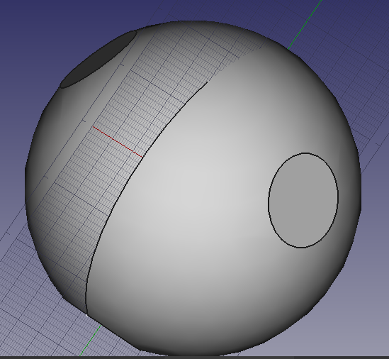
I then encountered another issue when doing the boolean cut:
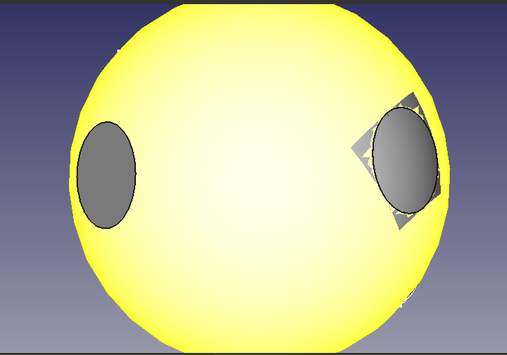
Two out four sites were not cut properly. They also had a square around the circle defined by the cylinder. Since I couldn’t solve this problem, I started from scratch and could eventually have the correct models.
After this I just had to print it. Or so I thought…
The printing adventure
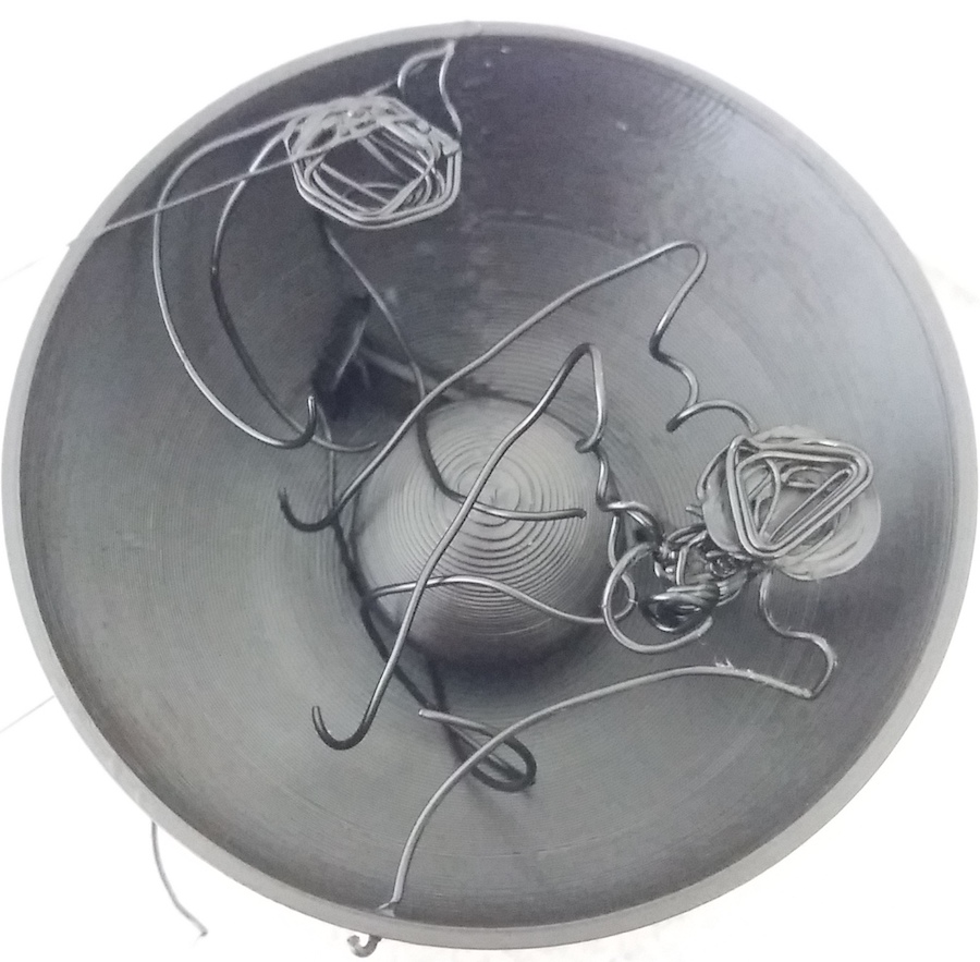
As an appetizer and a witness of the hardships I encountered during my journey, here is my Hall of Fails:
Slicers
This week, I used the proprietary software of MakerBot to use the corresponding printer. I also used the UltiMaker Cura slicer on the MakerBot as well as on the Creality 3D Ender printer. Unfortunately, when trying to launch the latest version of Cura on my MacBook, I encountered an error:
[29152] Error loading Python lib '/Applications/UltiMaker Cura.app/Contents/MacOS/libpython3.10.dylib':
dlopen: dlopen(/Applications/UltiMaker Cura.app/Contents/MacOS/libpython3.10.dylib, 10): Symbol not found: _preadv
When browing forums, it seemed that this error was due to my MacOS version. Indeed, I am using an old version (10.14.4). So I downloaded an older version of Cura from 2020: 4.7.0, and I could launch it without error.
I only used the very basic functionalities of these programs, so I didn’t notice too many differences in their usage. There is however a very convenient fuctionality that is available on Cura that I didn’t find on MakerBot: it is possible to select one of the faces to align it to the buildplate.
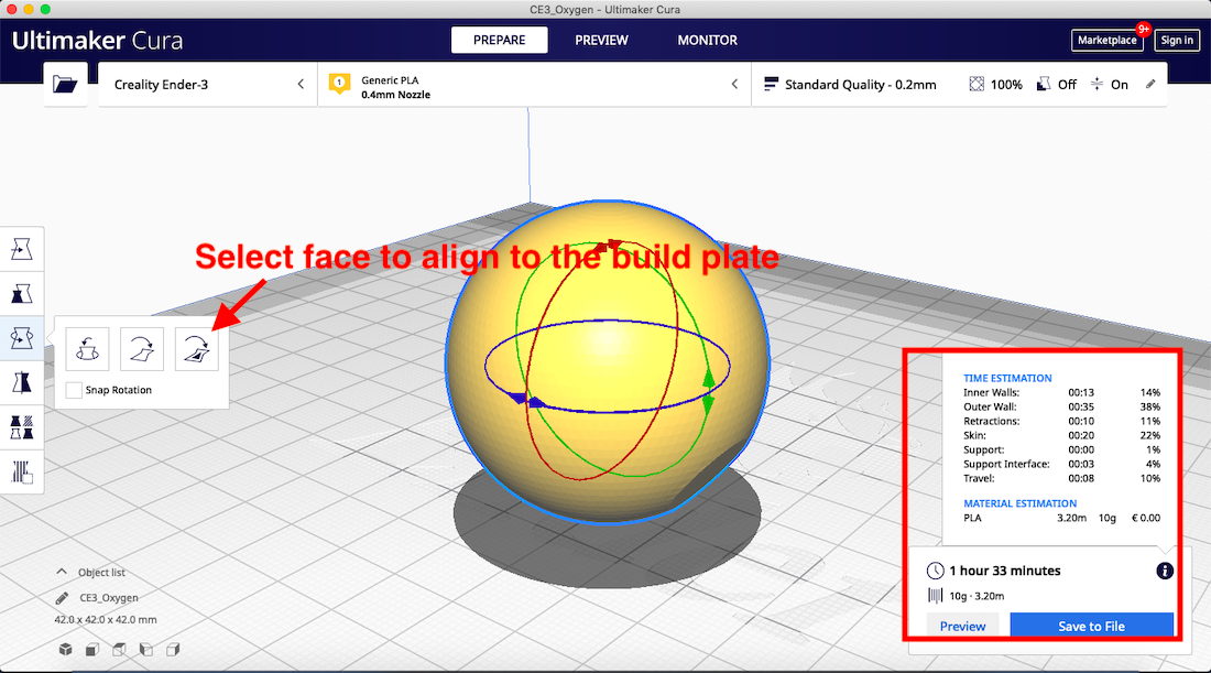
Another interesting feature that I saw in Cura was the approximation of the time for the job as well as for the mass of the object.
The slicers features I encountered this week were the followings:
- Shell: the number of layers printed for one surface of the model.
- Infill: when the model is defining an empty volume, the slicer can fill it with a grid. The percentage of the infill chosen by the user defines the density of this grid.
- Support: when there are overhangs on the model, the slicer can automatically create some supports that will help with the stability when printing these overhangs.
- Build Plate Adhesion: when the surface of the model in contact with the build plate is not large enough to ensure a steady printing, the slicer can automatically add a larger base which can later be detached.
Starting up the printer
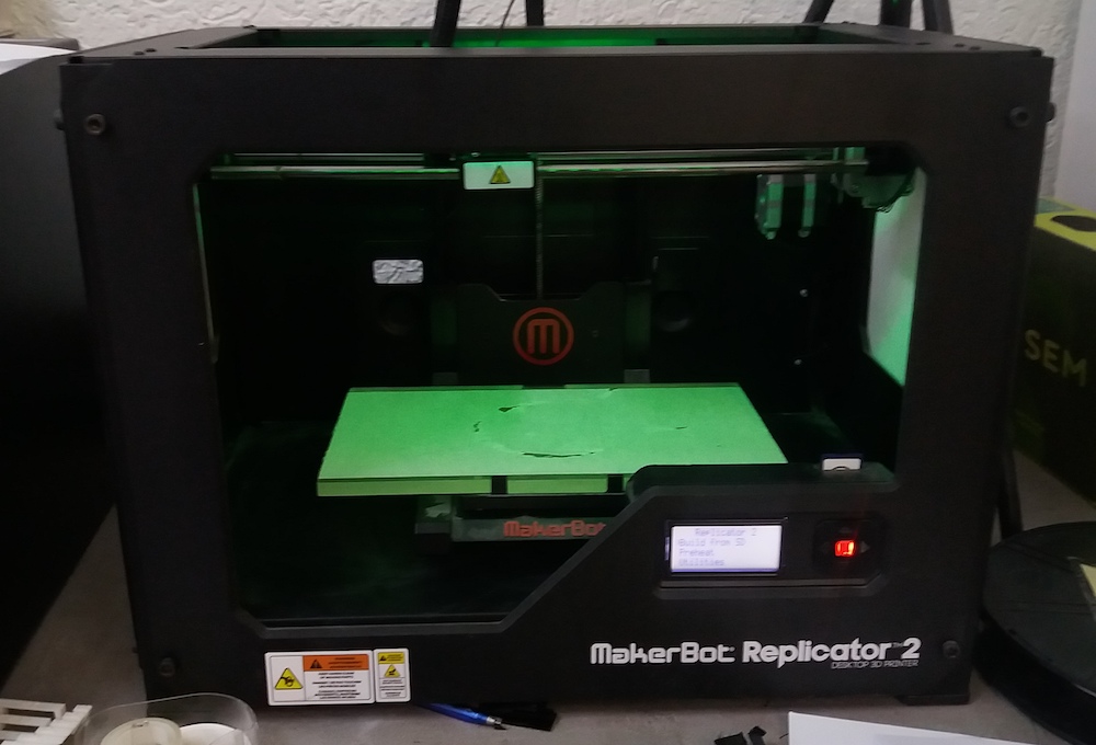
I used the MakerBot Replicator 3:
and the Creality 3D Ender:
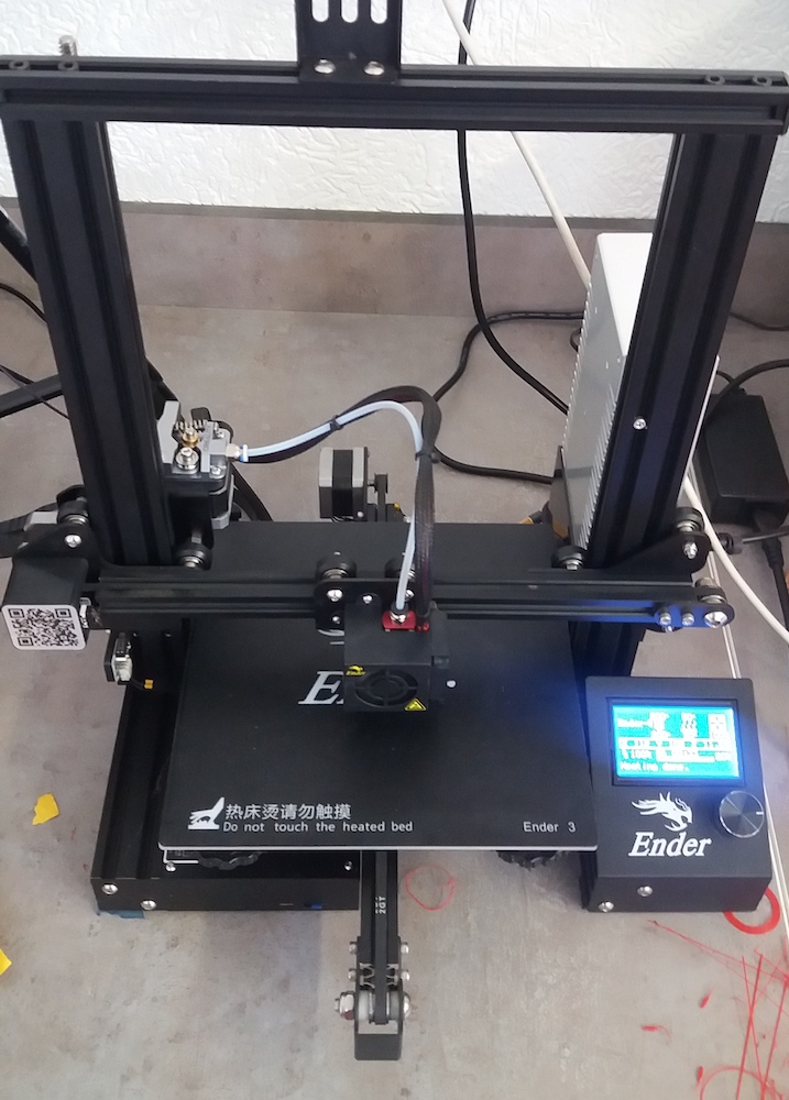
This last printer has a smaller build plate. It is also slower thant the MakerBot. However, it is more tolerant to lower quality PLA filament. Contrary to the MakerBot, it has a heating bed, which would enable us to print with ABS on it.
On the MakerBot, if the printed model has a surface in contact with the building plate which isn’t too small (like in the case of my atom models), the adherence is large enough so that there is no need to add some kind of build plate adhesion (like a raft). On the Ender, it is very often recommended to add a raft or an equivalent.
First, when starting a 3D printer, we will need to adjust the distance between the printing nozzle and the bed. In order to do this, we need to heat up the printing nozzle because it is slightly expanding in this process and it will then correspond to its state during the printing.
Then, we can adjust the bed height by tightening or loosening screws present under the build plate (three screws for the MakerBot and four for the Ender). We use the thickness of 1 paper sheet for the MakerBot slicer and of 2 sheets for the Cura slicer:
Hydrogen
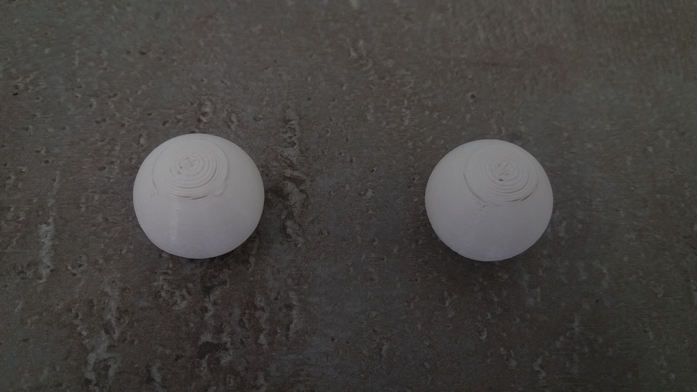
I started by printing the simpler model: hydrogen. In order to test the difference between the two slicers (MakerBot and Cura), I printed this model with both slicers. Here are the results:
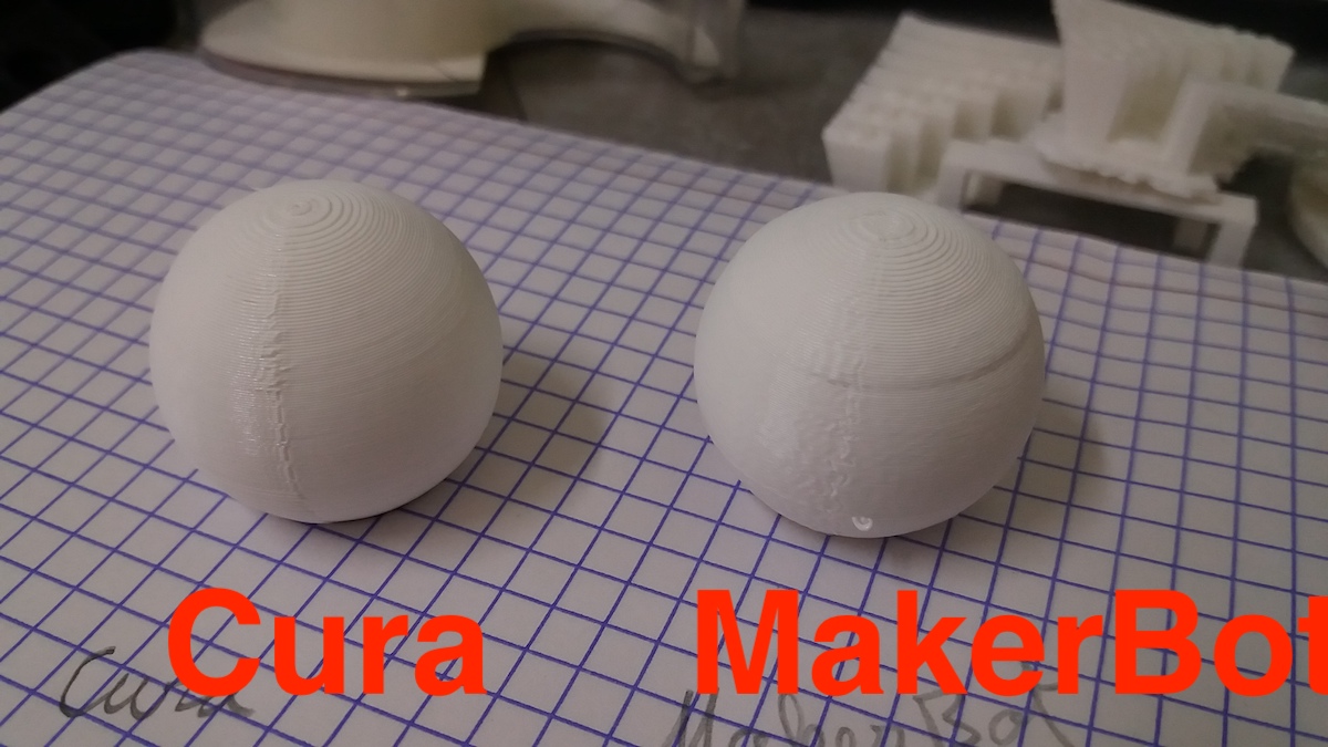
The Cura slicer seems to give a better quality result. The MakerBot seem looked less clean and the spherical part of the atom was not rendered properly.
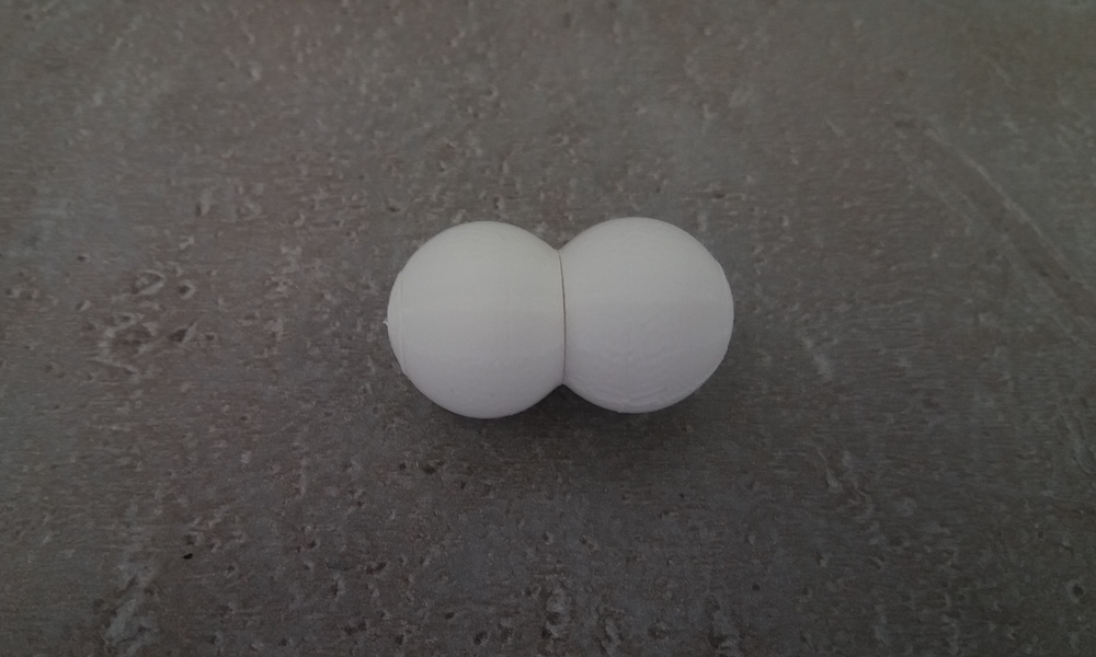
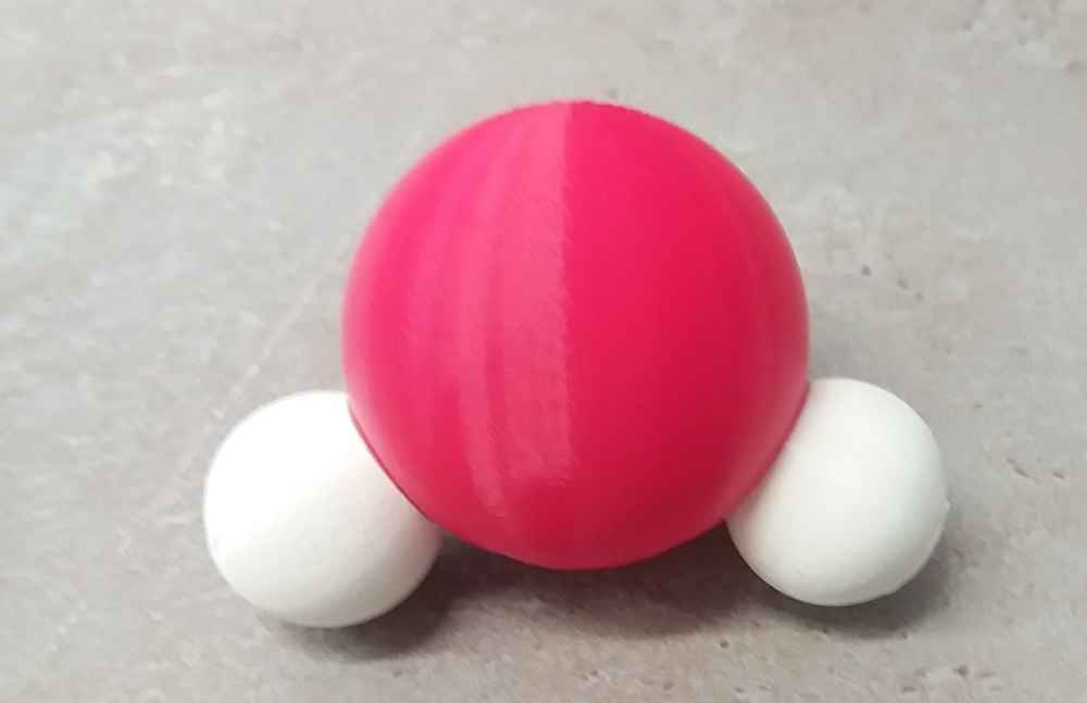
After printing the first hydrogen atoms, I chose to reduce the size of the atoms by one third in order to save printing time. Below is my first molecule:
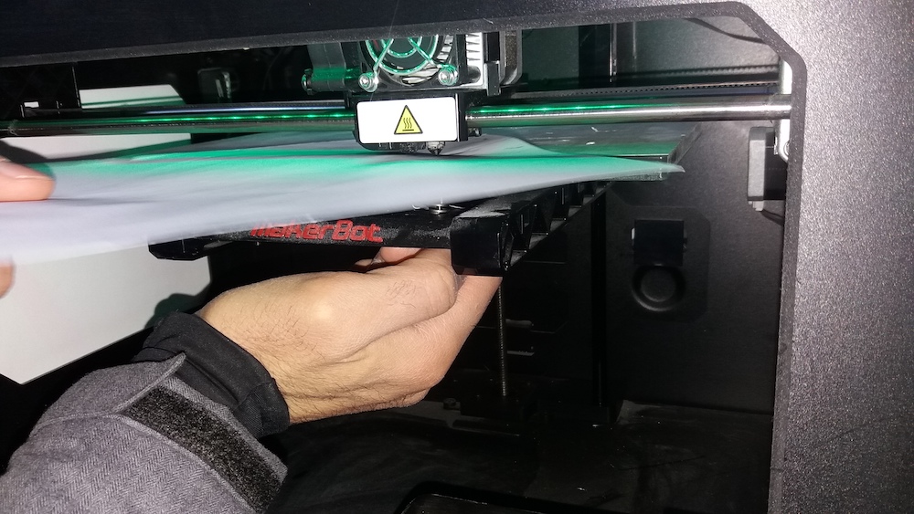
In order to put the magnet inside the pocket, I am pausing the printer (“cold pause” on the MakerBot).
Carbon
This model was much harder to print than the hydrogen. Since the faster MakerBot printer was busy when I started, I used the Ender. As explained above, I needed to add a raft for this printer.
The first problem arose when resuming the print after putting the magnet inside the first pocket. The magnet sticked to the printing head as soon as it passed above. This problem didn’t happen with the MakerBot. To resolve this issue, I paused again and placed a strong magnet under the build plate just below the model. This fixed the problem, but I must have shifted the model on the bed, because when resuming the resuming, the alignment wasn’t correct anymore:
After restarting, I could avoid this mistake when resuming the print and the first pocket passed without issue. However, when the printer started to print the three other pockets, I realised that I made a very stupid mistake: the nozzle was starting to try printing a part of the pocket which wasn’t yet attached to anything! How could I miss this!?
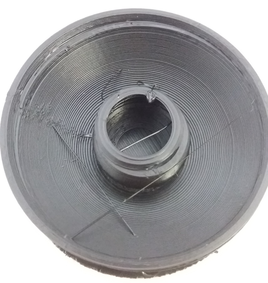
Unfortunately, I couldn’t resolve this problem by letting Cura automatically add supports, because it would fill the pockets with unremovable supports. I then had to manualy add some small pillars to support the printing of these pockets. The pillars I designed were too small and one collapsed before even starting to print the pockets. The others were not wide enough and couldn’t correctly support the printing (and eventually collapsed):
I had to model some larger supports, but it was enough for this day. The next day, having designed the larger pillars, I resolved to resume the printing of the carbon atom. I could use the MakerBot printer, which would be faster and remove the problem of the printing head attracting the magnets. After almost one hour of suspense, I could notice that my supports were large enough this time:
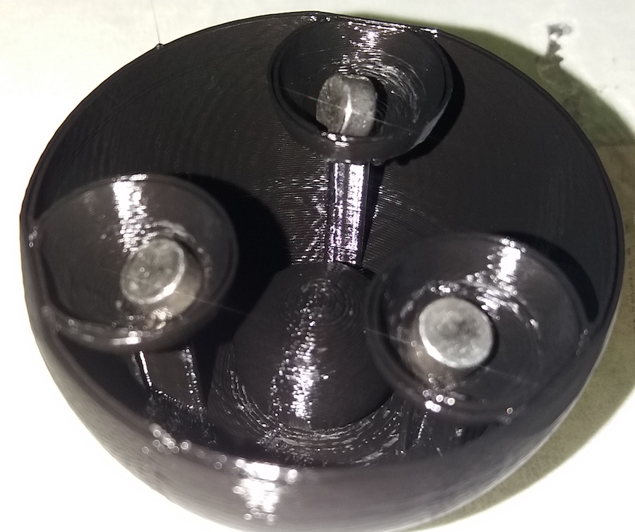
After all these trials and errors, I could finally print my first carbon atom:
Oxygen
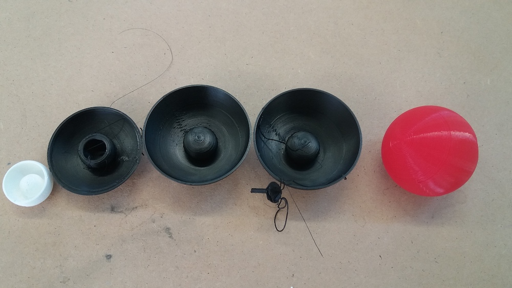
Enriched by the experience I gained printing the carbon atom, the oxygen was easier to print. I made it on the Ender, so I had to add magnets outside of the shell in order to prevent the others to stick to the printing head:
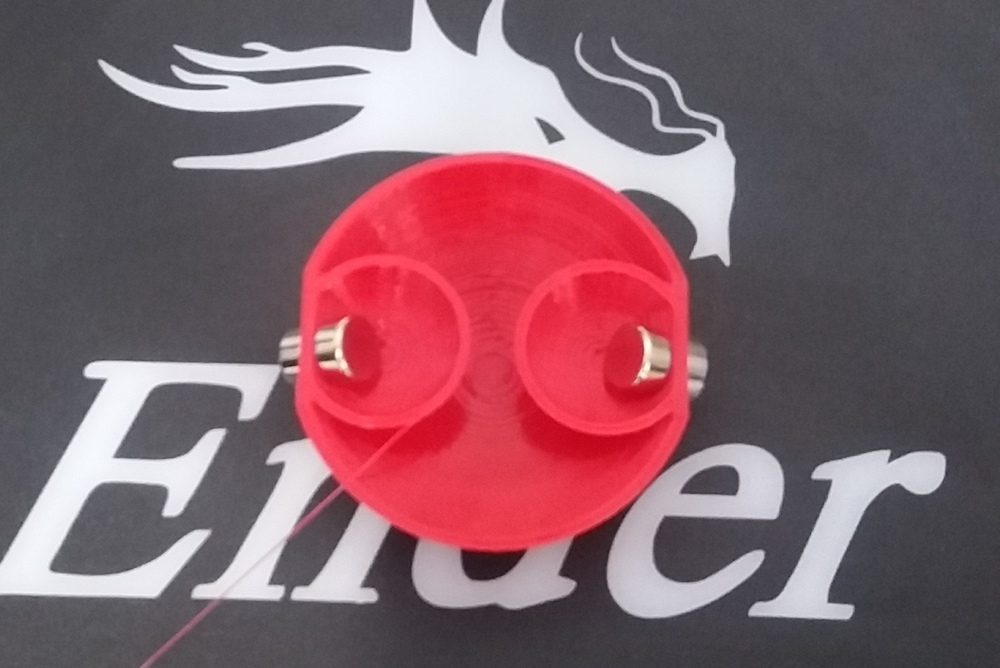
The printing was done without issue. However, when I tested it with other atoms, the attraction was almost non existent. After some investigation, I realised that, since the oxygen was smaller than the carbon, the pockets inside the outer shell were too close to each other. The magnets experienced more attraction inside the shell and, when approaching another atom, the force wasn’t big enough to overcome this attraction. This could probably be fixed by decreasing the size of the pocket. Unfortunately, I don’t have enough time to make more trials this week and this will remain an unresolved issue… for now.
I still manage to stick some other atoms to it by approaching another stronger magnet to overcome the inside force:
Results
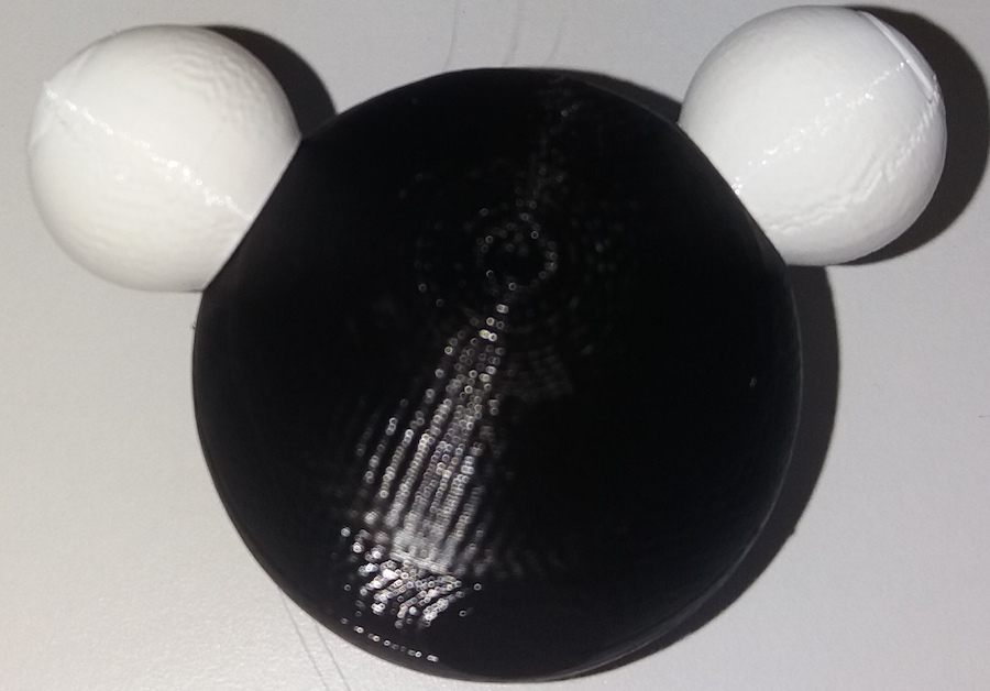
Here are some example molecules that are possible to make with the kit in its current state.
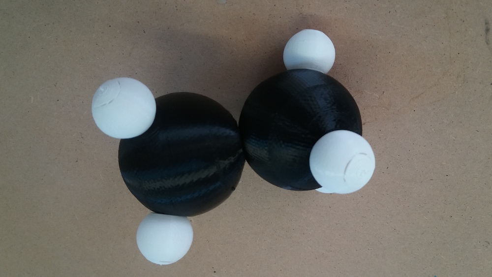
Ethane:
Dimetyhl ether:
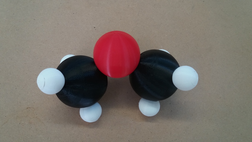
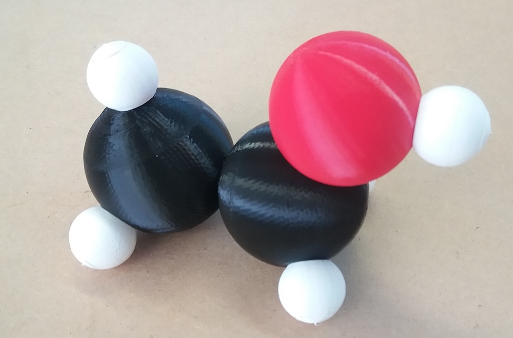
Ethanol:
Conclusion
I had the idea of making a molecule model quite early in the week and thought that I could 3D print many atoms. My expectations quickly had to be revised when I faced the issues that I described above. Also, the design of the atoms of oxygen and carbon with FreeCAD were harder than expected and the printing time for the bigger atoms wasn’t as short as expected. I settled for a minimum working model of two carbon atoms, one oxygen atom and six hydrogen atoms.
I was also frustrated with my lack of time for fixing the mistake I made when designing the oxygen atom.
As for the 3D scanning, it wasn’t very successful for me. The technique I used, without LIDAR technology, is more sensitive to the quality of the object scanned. As my object was not ideal, the result was somewhat lacking.
Files of the week
ZIP of the stl file of the 3D scan
Freecad file of the designs of the atoms