20. Project development

Week 20 · 2023.05.31-2023.05.07 During this week I developed the final tasks in order to have the Robuddy project ready.
- [x] Account for tasks that have been completed
- [x] Tasks remaining
- [x] What has worked what hasn’t?
- [x] what questions need to be resolved?
- [x] what will happen when?
- [x] what have you learned?
‘Final project development process’
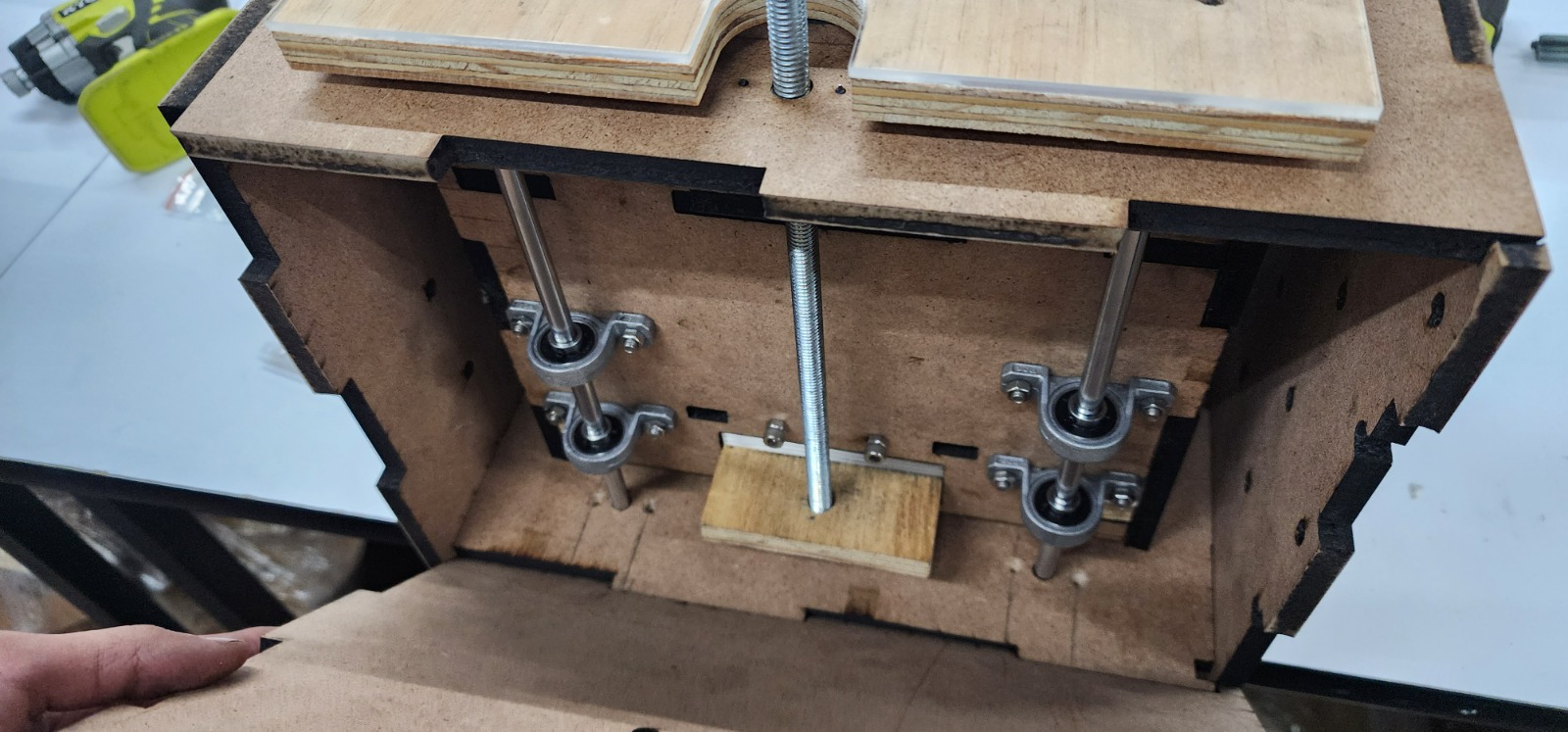
For the last week, the drawer was completely designed and about to be finished, the electric sockets were printed and armed. The wood frame for Robuddy was finished. The gripper and its electronics were almost finished, I was waiting for the branching cable to arrive (I already found out that the battery had to be drained to mantain it working)
Tasks for last week include:
- Setting in place the Robuddy
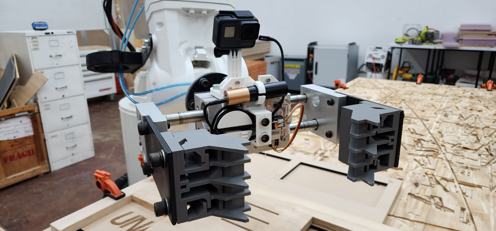
- Adjusting and milling the slots for the gripper in the piece to be processed
- Finishing isometric exploded geometries
- Filming the explanation with the project and robotic arm
- Designing comparison and running simulation for serial and parallel multitool robotic fabrication (if I don’t finish this will be the first thing out of the video)
- Making the subtitles and credits for the video
- Putting together the video, final cut (music was selected since the draft)
- Finnishing the slide
- Documenting and uploading
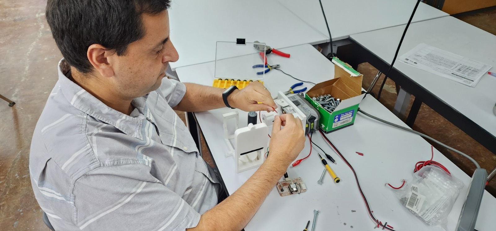
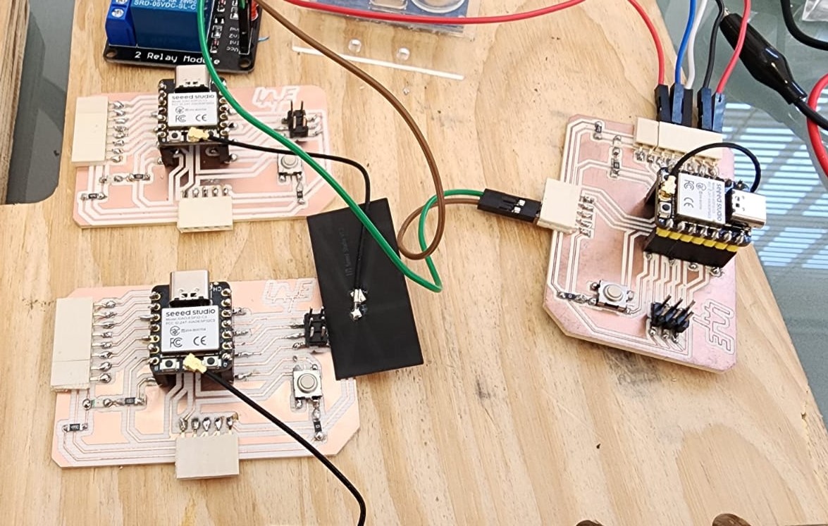
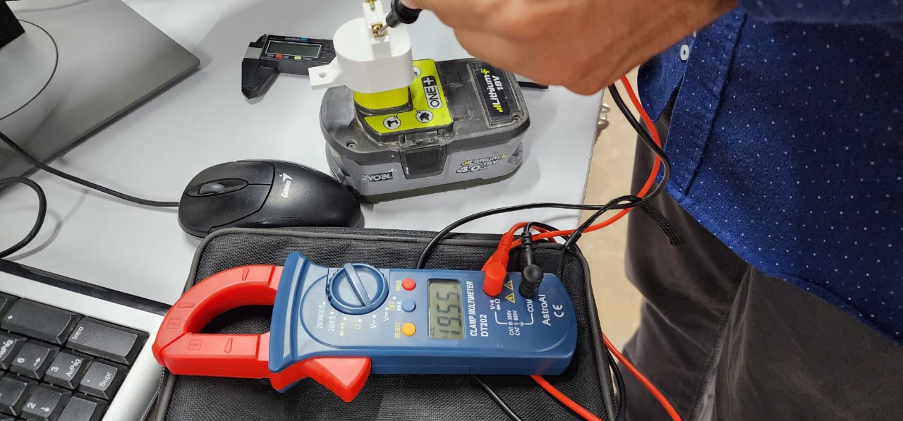
While electronics were set and proved. What didn’t work · I found out one cable was completely out of a relay socket and that the manual router needs a manual reset for working.
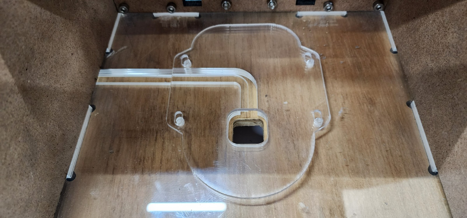
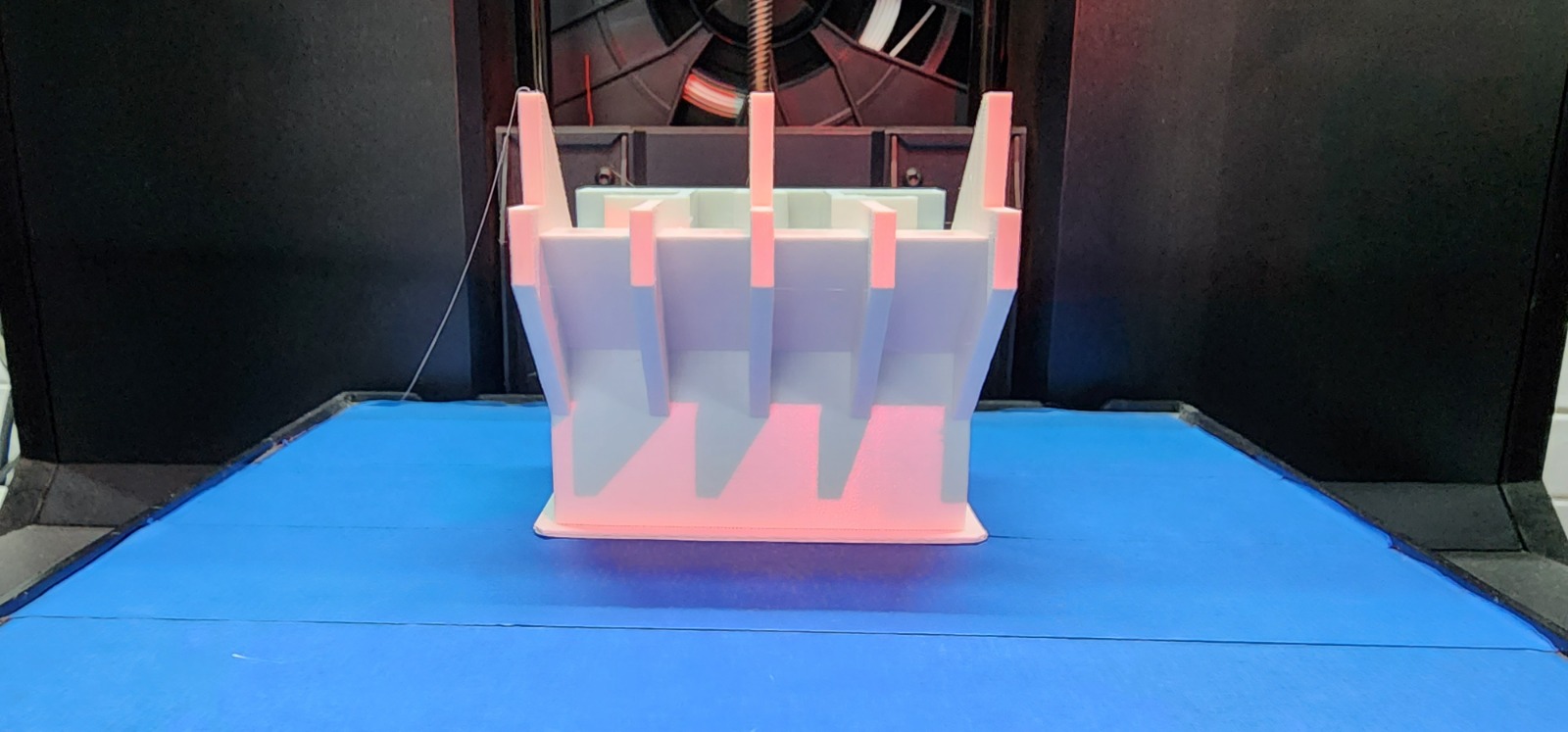
While adjusting the tracks for the gripper one of the gray paddles broke, so I had to print a new set (since the would be white this time)
Anticipated conclussions in learning
It was amazing how the heatwave we were going under (about 28ºC in the – usually cold– lab) worked great for avoiding warping in the 3d prints.
I wanted to keep the video exactly within 1 minute, but there was so much to put in, that I had to stretch some more seconds. I learned that sometimes content rules over time precission (probably always).
I found a way to place footage of myself doing the tasks, in the form of multi screen bloopers in the credits.
I know that when you get to the final sprint you have to concentrate and leave out what is not essential, and when you become elder you plan better so everytime you allow more time for the tasks and you end up leaving less out.
Electronic previous advancements
Electronic boards
Connecting the battery advancements
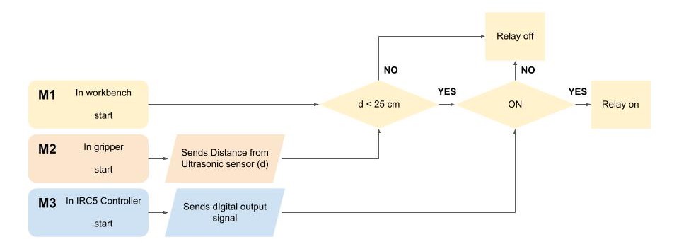
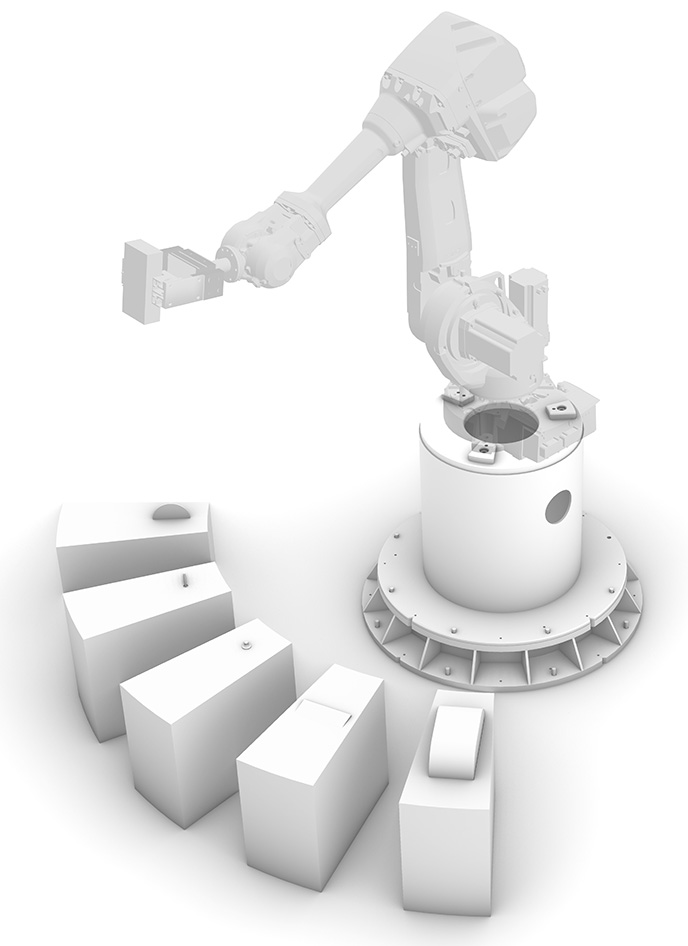
Every tool will be connected to relays through a microcontroler that will receive the signal from the robot controler (such as ABB IRC5) for swicthing on and off of every tool: The robotic arm will have a gripping mechanism that will be able to fix different parts (one at a time with current gripper adaptation) in a firm position to approach every tool firmly and with precision.
The main challenges detected so far are:
- being able to provide a firm grip for each part while grabbed by the robotic arm
- a firm grip for the handheld tool,
- a precise approximation between tool and the part
- being able to put together the electronics with the input comming from the robot controller.
The potencial users are fablabs, robot labs, makerspaces, and entrepreneurs that want to start with robotic fabrication, investing mainly and firstly in the robotic arm and being able with a small investment to start machining different pieces and materials
The Materials foreseeing for now are mdf for case components, arduino controller, electronic parts, textile straps and 3d printed parts or 3d machined for fixing the tools.
 Handheld multitool bank for robotic fabrication
Handheld tool type for bank
 |
 |
 |
|---|---|---|
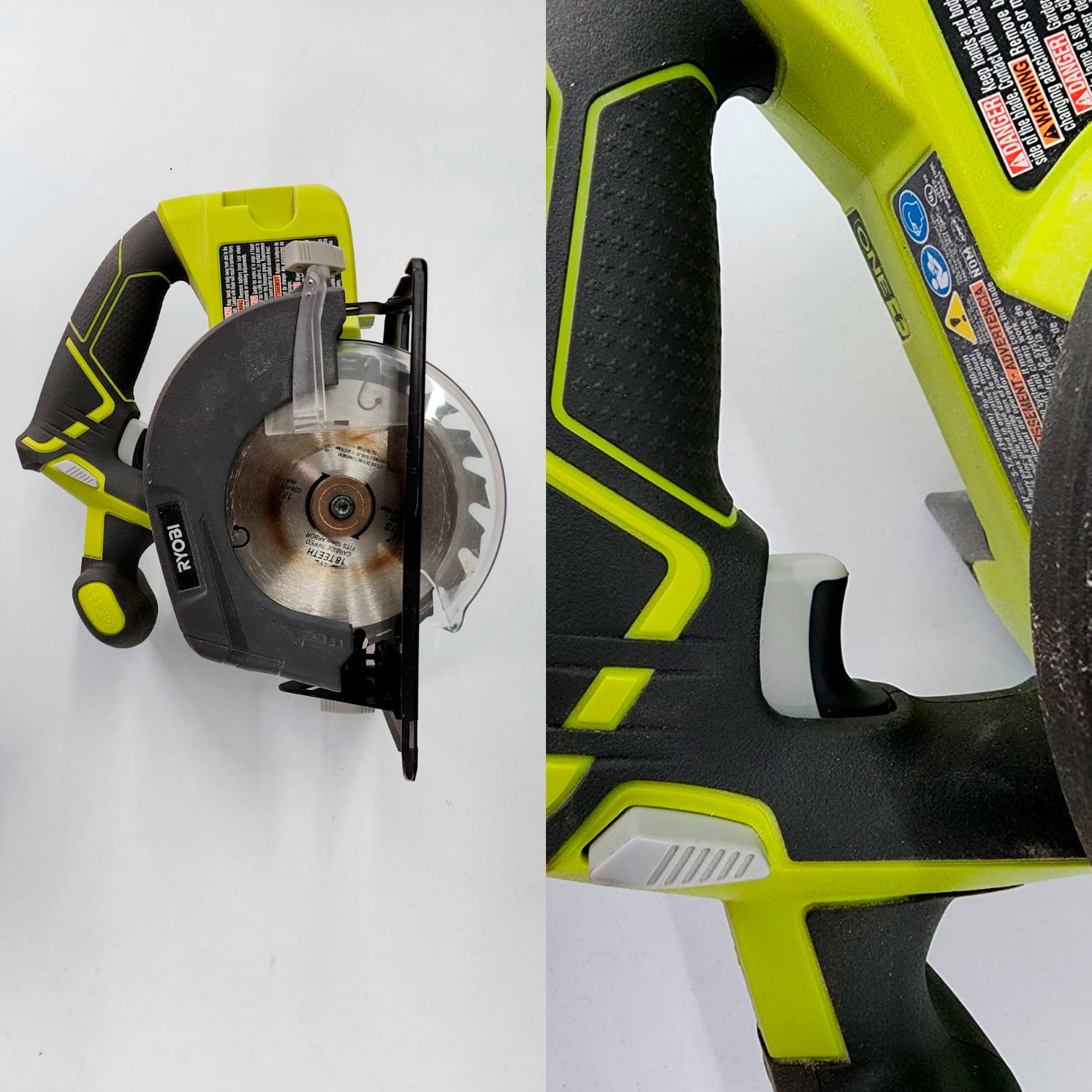
Circular saw · trigger switch activating method |
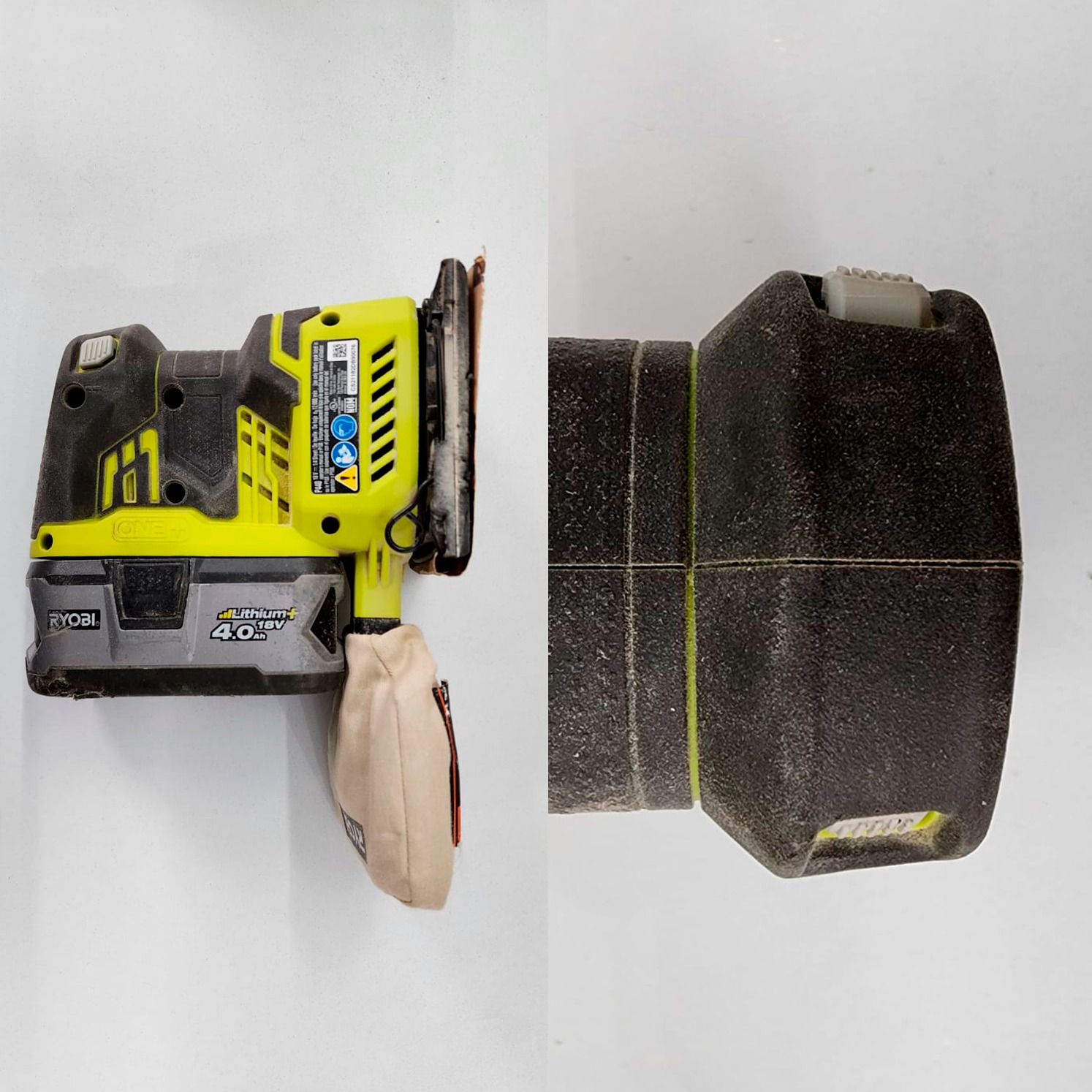
Sanding machine · linear sliding switch activating method |
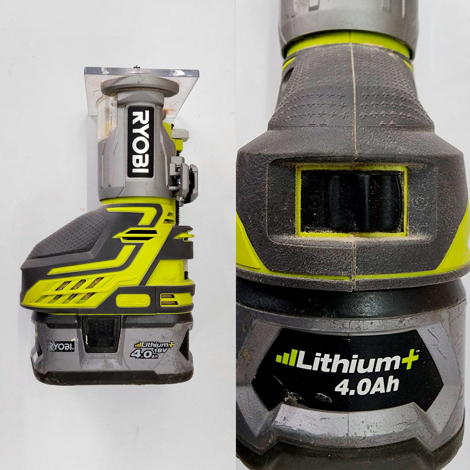
Router · curved sliding switch activating method |
Having three main types of activating systems, it is possible to think in activating through the common denominator, the power source. I can possibly work in a sliding mechanism over the trigger, since de drill is sensible to pressure.
 |
 |
 |
|---|---|---|
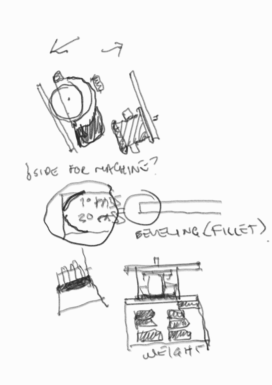
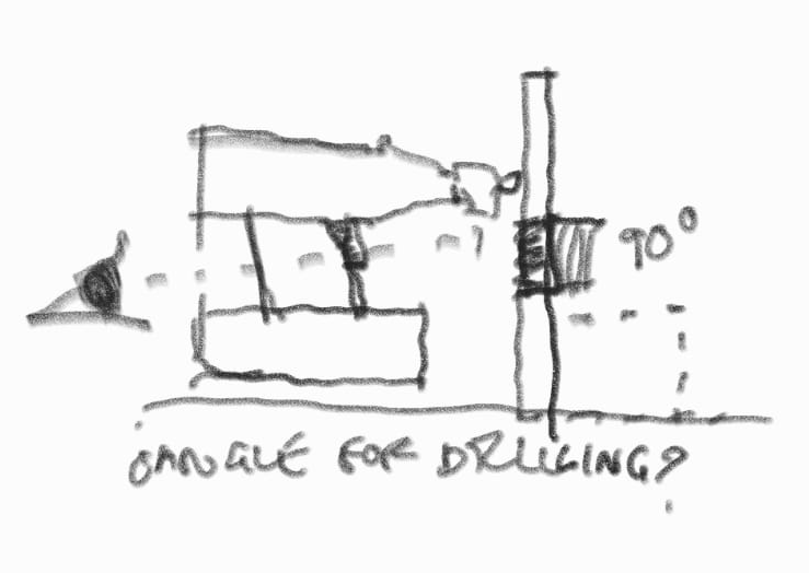
Following issues to be taken in account include the side and angle of aproximation, and the weight to include so the bank will keep its position. |
It is desirable to observe how the tool and were will it start acting upon the piece to be processed. |
What will the maximum size of the processed piece will be and how will the grip from the robotic arm develop |
 |
 |
|---|---|
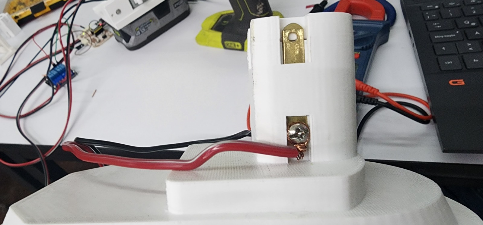
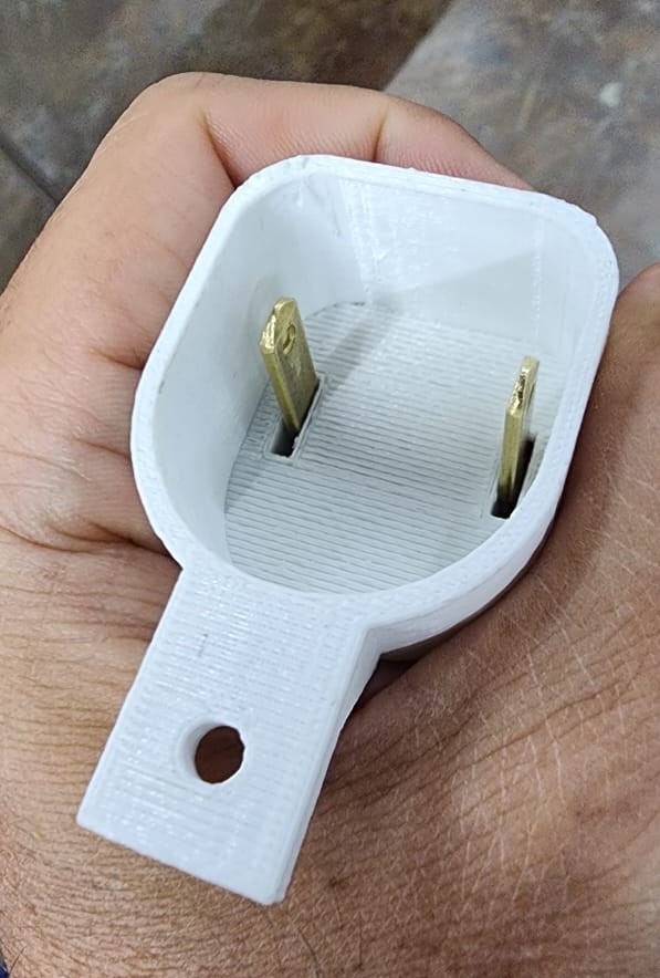
In order to mediate evenly between every tool's power, the battery plugs to a female connector while the powertool plugs to a male connector |
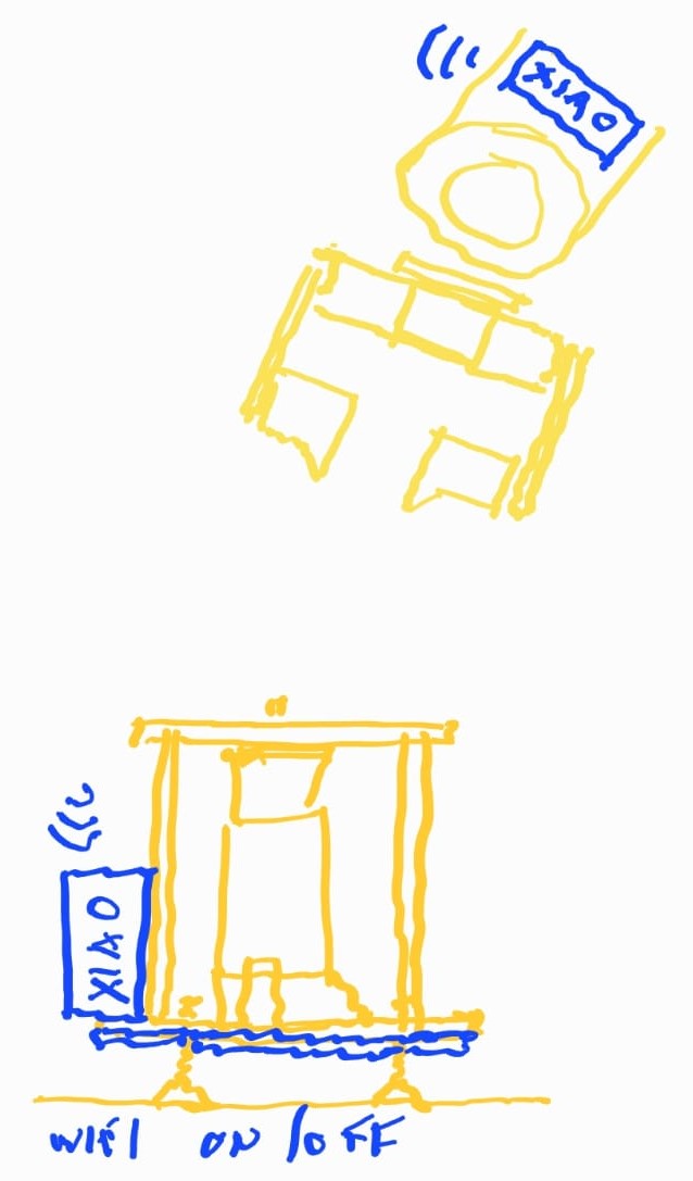
Electronics may include wifi communication for powering on and off the power tools |
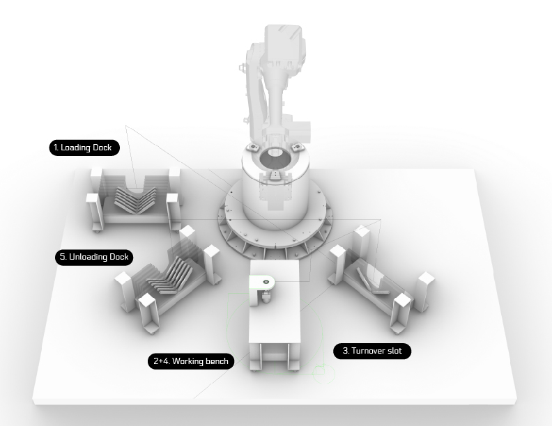
Initial Sketch
In the general scheme, I have thought of a bench that holds pieces to process, a bench for pieces processed, a bench for processing and a bench for flipping pieces.
Second spiral design
Programming diagram flux