3. Computer Aided Design · CAD
Week 03 · 2023.02.01-2023.02.08
‘CAD Drafting’
Assembly of work models and drawings
This week I worked on measuring, drafting and modelling diferent parts (while evolving the design) into what my final project might start to look like
Checklist for the tasks assigned:
- [x] Modelled experimental objects/part of a possible project in 2D and 3D software
- [x] Shown how you did it with words/images/screenshots
- [x] Included your original design files
Some model scouting for handheld tools
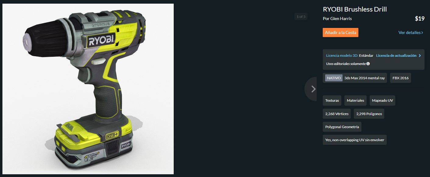
I looked around for some 3d models of usual objects (in my case, the Ryobi tools) so I can work around with the rest, and wouldn’t have to repeat what has already been done, and didn’t find much. I found a model of drill, which is different from mine, it is not a free model and anyway I’m not so sure I will end up using a drill since my order of preference so far goes to the following tools (already updated from the apprentissage of this week):
- Routing · As for now is the most important tool, since of what I have thought as an example of application has to do with filletting some boards with a roundover bit on both sides
- Turnover slot · I want to be able to grab a board on one side and then grab it from the other side with the robotic arm (so I can fillet both edges) this might be the first idea that adds value against using a robotic arm with the tool on the end axis
- Edge painting solution · After processing some board pieces, I’m interested in painting the edge so I can add a homemade solution that may help to envision a third way of processing pieces, since routing is pretty common, and turning over doesn’t show as a result on the piece, then so far we would have a conventional process put into pieces until this detailing solution comes along
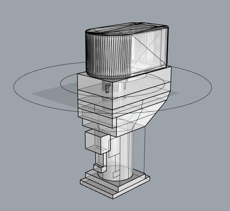
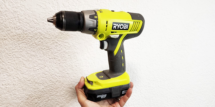 My own drill
Then I started modelling first the battery, since I thought it would be the part that repeated the most among the tools.
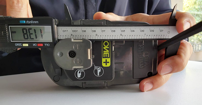
For this purpose I addressed different ways of gathering measurements
- By live measurements with a Vernier caliper · I inmediately noticed that everything was curved, it has many details and there is not really an easy way of measuring this geometry
- I tried taking pictures, even tried a rough 3dscanning with polycam that didn’t come very well
- I scanned the lower part and then tried to outline the edge, but the scan came so dark that it was hard to detect the edge…
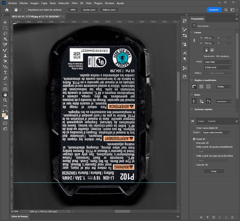
So I went back with the caliper, helped by a hexagonal bar and some patience to start with a parametric approach
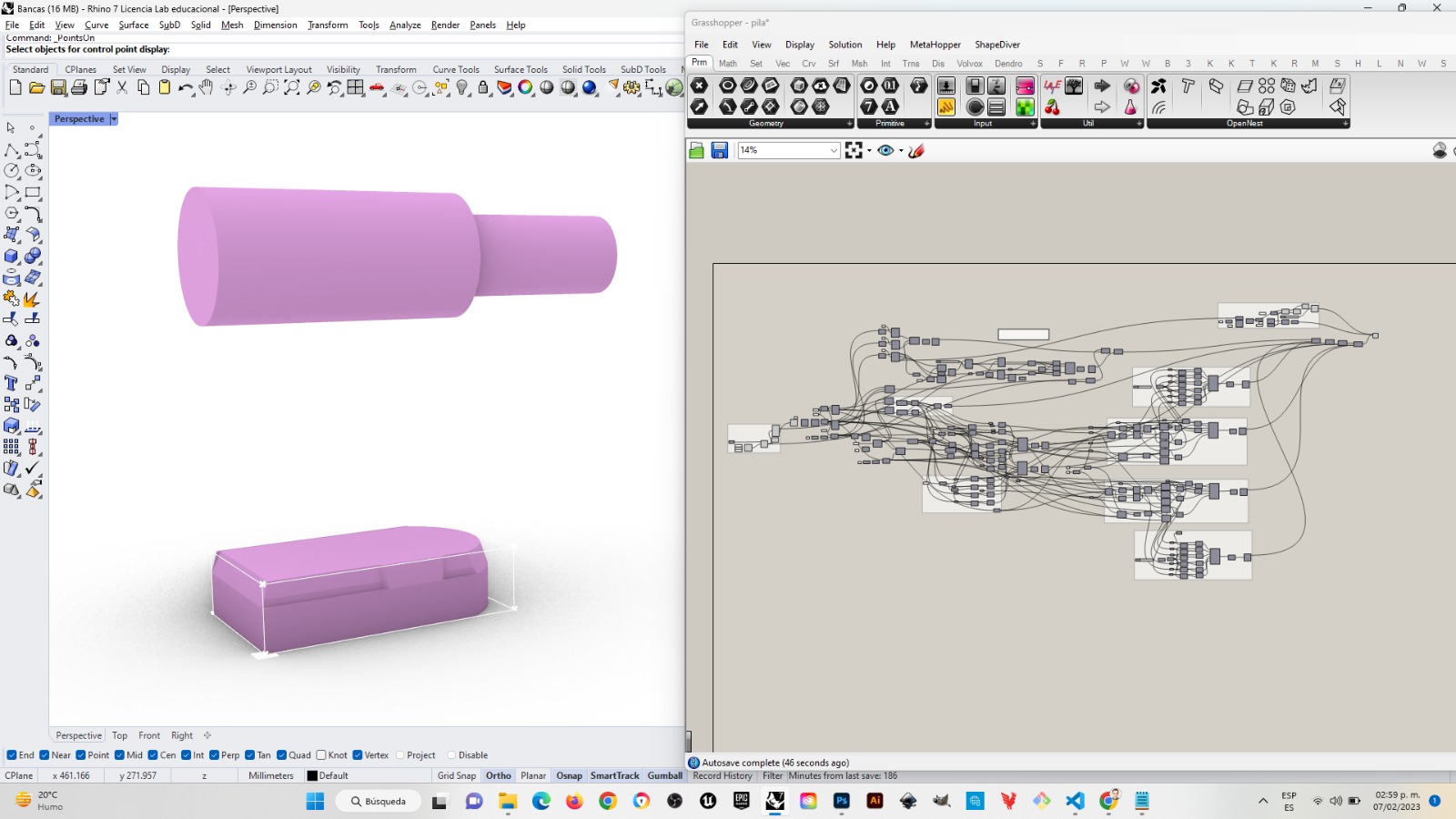 Battery grasshopper file
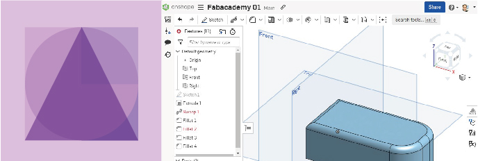
This was taking so much time that I decided to make more rough models of the tools really needed. Then based on the router pictures available I made a model, first based in the profile to get the measurements in one side, then with a model (of a double battery I found in Thingiverse) I set the measurments in the other direction.
I tried Onshape online, which looks nice, although I’ve learned that if the program You currently use is powerful enough to develop in a state-of-the-art fashion what you need, don’t shift. I have used in the past: Autocad (I was certified in 2012), Maya and 3DSMax for developing models. Now I try to keep it simple within Rhinoceros and Grasshopper.
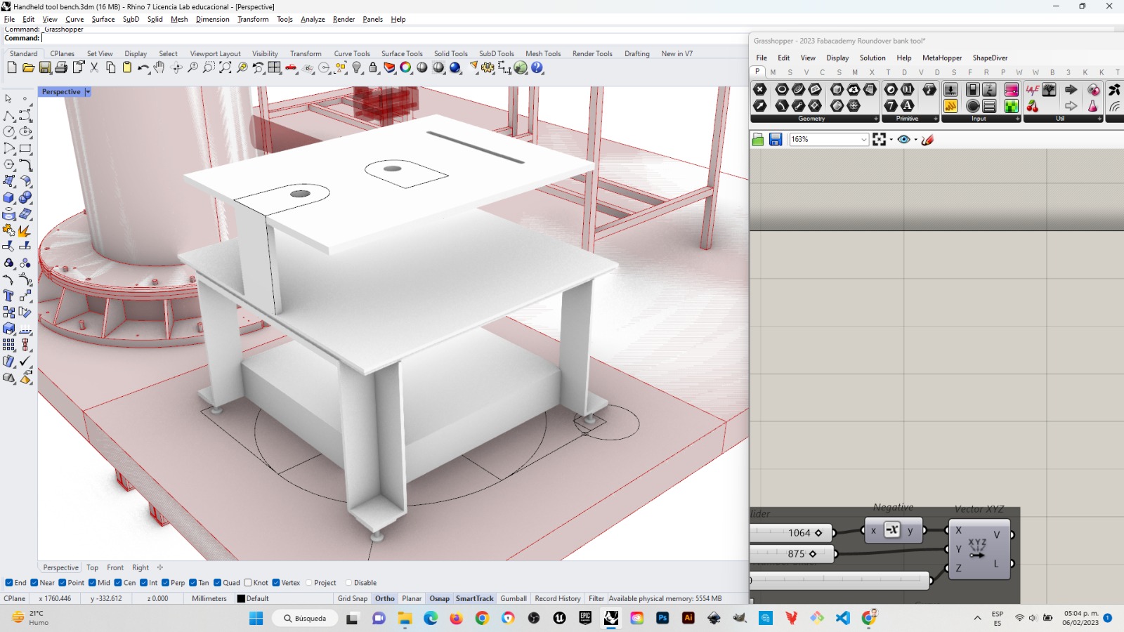
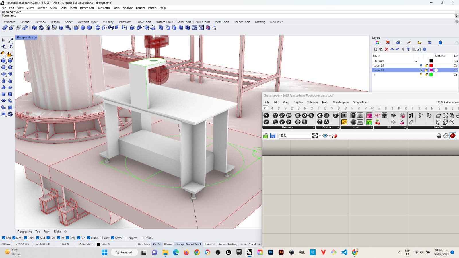
Stablishing a workflow based on previous knowledge that manages to embrace the new
After this I started modeling what would be the working bench for my project and then everything flowed smoothly
The steps taken for this version of the bench started with:
- Modelling a box 45cm per side
- Developing the corner plates 10 cm x 10 cm x 1 cm in order to receive threaded levelers that may have casters such as these
- The levelers were build with cilinders and truncated cones, the center points over the solids were sometimes acquired by drafting diagonal lines and using object snaps for aiming the middle point. The height for pushing everything up and adjusting the levelers has to do with that from the comercial leveler cited before.
- Vertical and corner top plates were placed following the dimensions of those in the lower corners
- Then other solids followed to make a flat surface
-
On the first iteration I thought of gathering three comercial tools: a circular saw, a compact router and a drill…
-
Then I though that if the piece being processed had to go around each tool grabbed by the griper from the robotic arm I would face to main isues
- first · there was not enough space for a piece of about 30cm in diameter to go around without hitting other tools, and;
- second · the gripping device attached to the gripper would protrude from the surface therefore I had to rethink how to place a piece with enough space under the objetive surface for the gripping addons to go freely around. I also had to give enough space for the piece to have at least 30cm in diameter and being able to be moved easily.
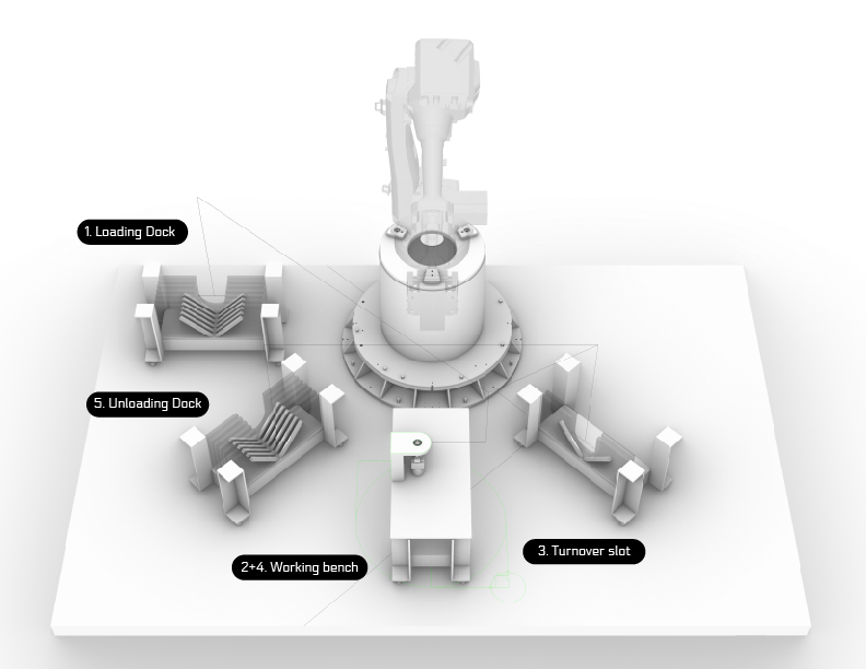
Second turn for the spiral
After these first steps I realized it will be richer to have a solution for a handheld device (that should set the basis for others), have a turnover slot for shifting sides in grabing pieces, a loading rack for ‘raw’ pieces and an unloading rack for ‘worked out’ pieces.
Then from the base bench I developed posible racks and slots that integrate following the next diagram:
Work bench setting .obj + .mat files
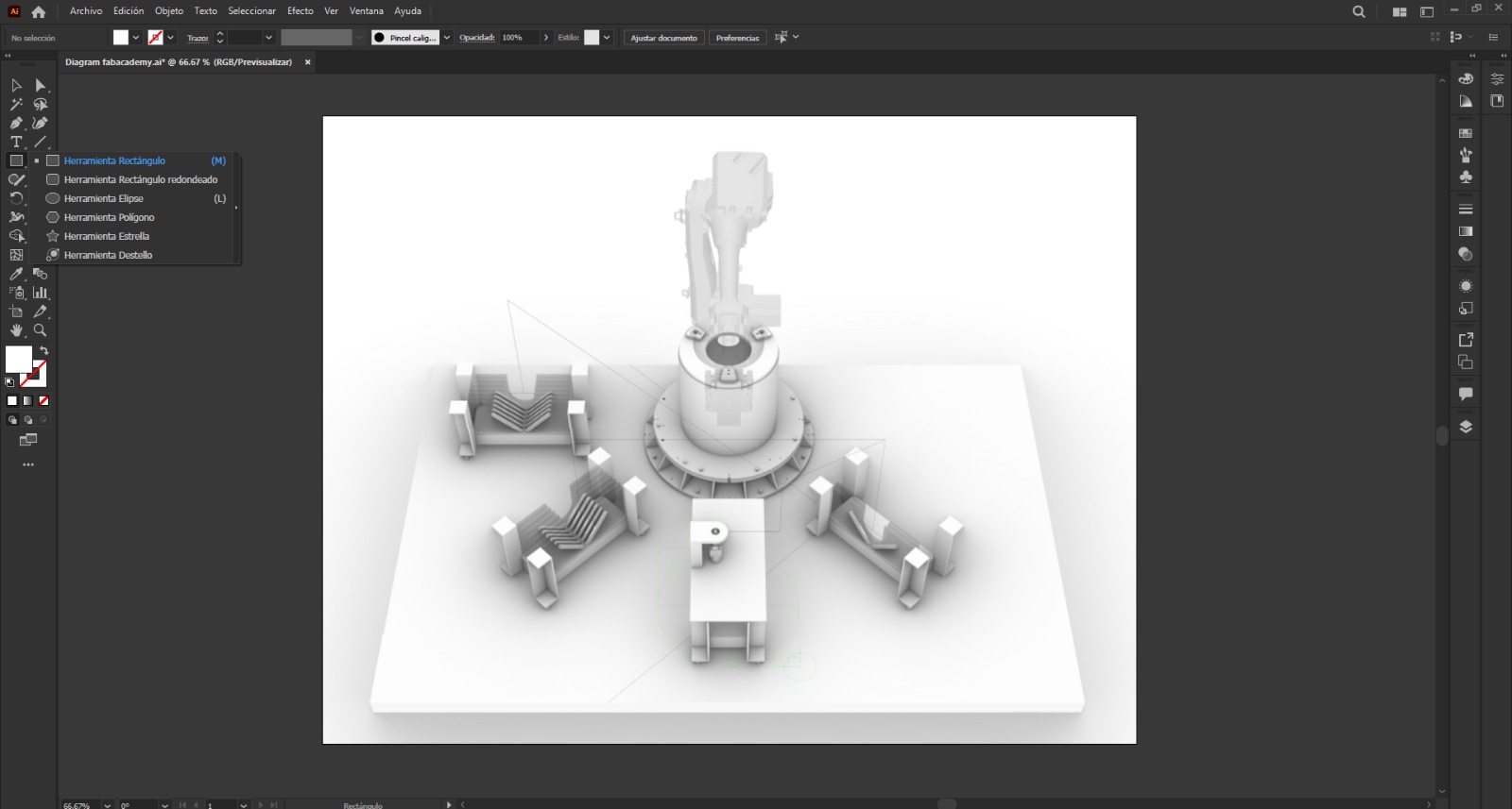
How I did the robotic diagram on 2D Software
After exporting the image of the 3D model from Rhinoceros 3D to png I opened a new document in illustrator and dragged and dropped the image from Rhino.
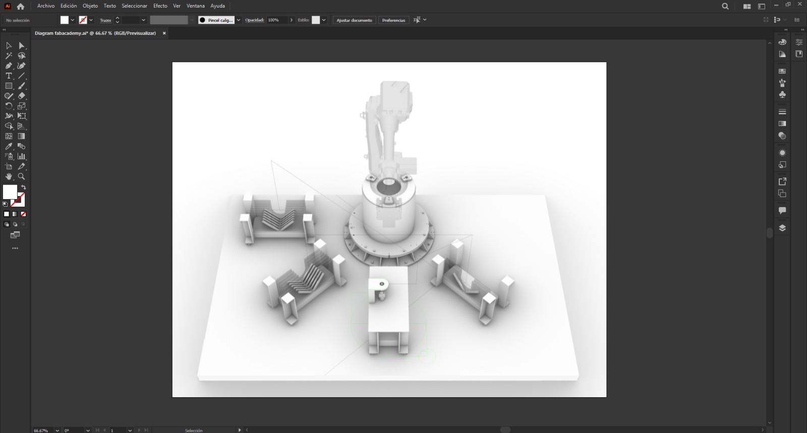
Then I generated a new layer so I could be sure I would put all the signs on top of the image without worrying who would be on top
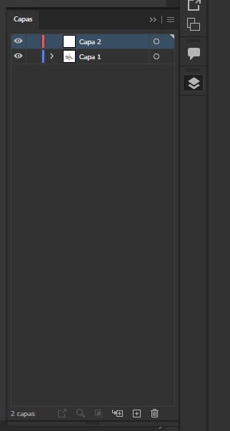
Then I made a long click on the rectangle tool to open the other options where the round corner rectangle tool is and I selected it
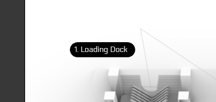
Then I started drawing a rectangle with round corners for the first tag

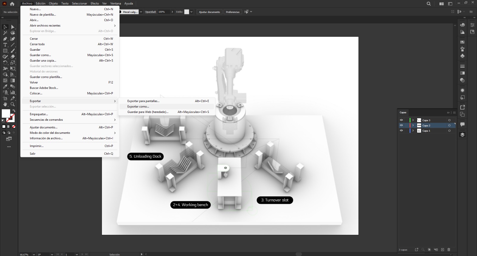
I placed a text window with the text tool and typed the first tag, and changed the font by selecting the text and choosing ‘Electrolize” font on the menu. Then I grouped the round corner rectangle with the text for the full tag combo. I copied the tag and edited the text correspondingly.
Then in file tab, I selected export, and exported the image as a png, again.
Since I was not paying much attention to the working tables, I left this options unselected.
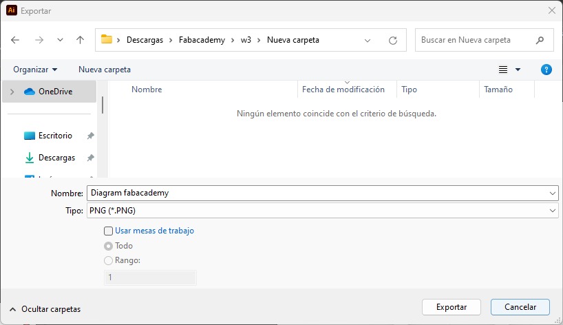
Then clicked on export.