5. Embedded programming

Week 05 · 2023.02.15-2023.02.22
This week we worked on delivering code to different electronic architectures with the aid of Arduino IDE, I worked following the steps recomended by my instructor for the main understanding of the proccesses involved, and tried different alternatives individually.
- [x] Linked to the group assignment page Fablab Ciudad de México Page
- [x] Documented what you learned from browsing through a microcontroller datasheet.
- [x] Programmed your board to interact and communicate
- [x] Described the programming process(es) you used
- [x] Included your source code
- [x] Included ‘hero shot(s)’
Preparing for delivering code · Seeed XIAO RP2040
I started by following the tutorial in this page to understand how to deliver code to Seeed XIAO RP2040.
-
Press and hold the BOOT buttion (didn’t make any difference if I didn’t) and then connect the Seeed Studio XIAO RP2040 to the PC. In my case I heard the typical USB connection sound on Windows
-
Download and Install the latest version of Arduino IDE according to your operating system. I downloaded Arduino IDE from [here] (https://www.arduino.cc/en/software)
-
Launch the Arduino application and Add Seeed Studio XIAO RP2040 board package to your Arduino IDE, by navigating to File > Preferences, and fill Additional Boards Manager URLs with the url below:
https://github.com/earlephilhower/arduino-pico/releases/download/global/package_rp2040_index.json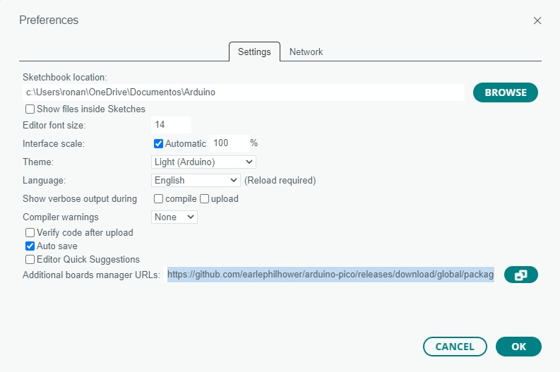
-
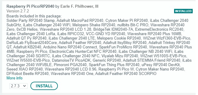
Navigate to Tools-> Board-> Boards Manager…, type the keyword “RP2040” in the searching blank. Select the lastest version of “Raspberry Pi Pico/RP2040” and install it.
-
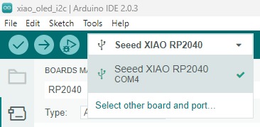
Select your board and port.
-
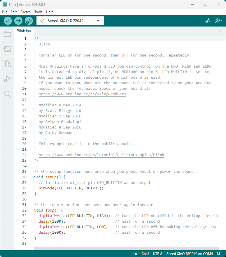
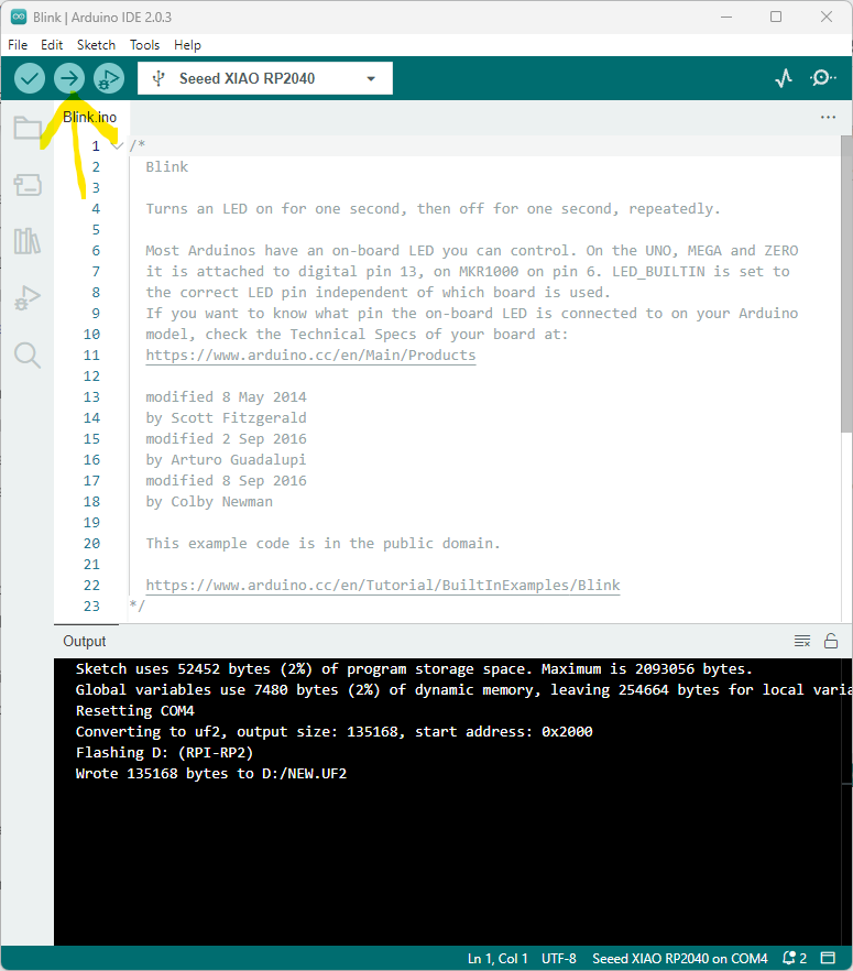
Open the Blink example by navigating “File → Examples —>01.Basics → Blink”
-
Pressed the upload button, waited for some process to carry out and then the user LED started blinking
Seeed XIAO RP2040 + Grove - OLED Display 0.96” (SSD1315)
-
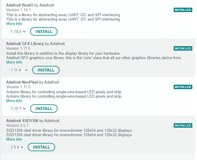
Open Arduino IDE, navigate to Sketch > Include Library > Manage Libraries… to search the library. Then I searched and installed these libraries:
-
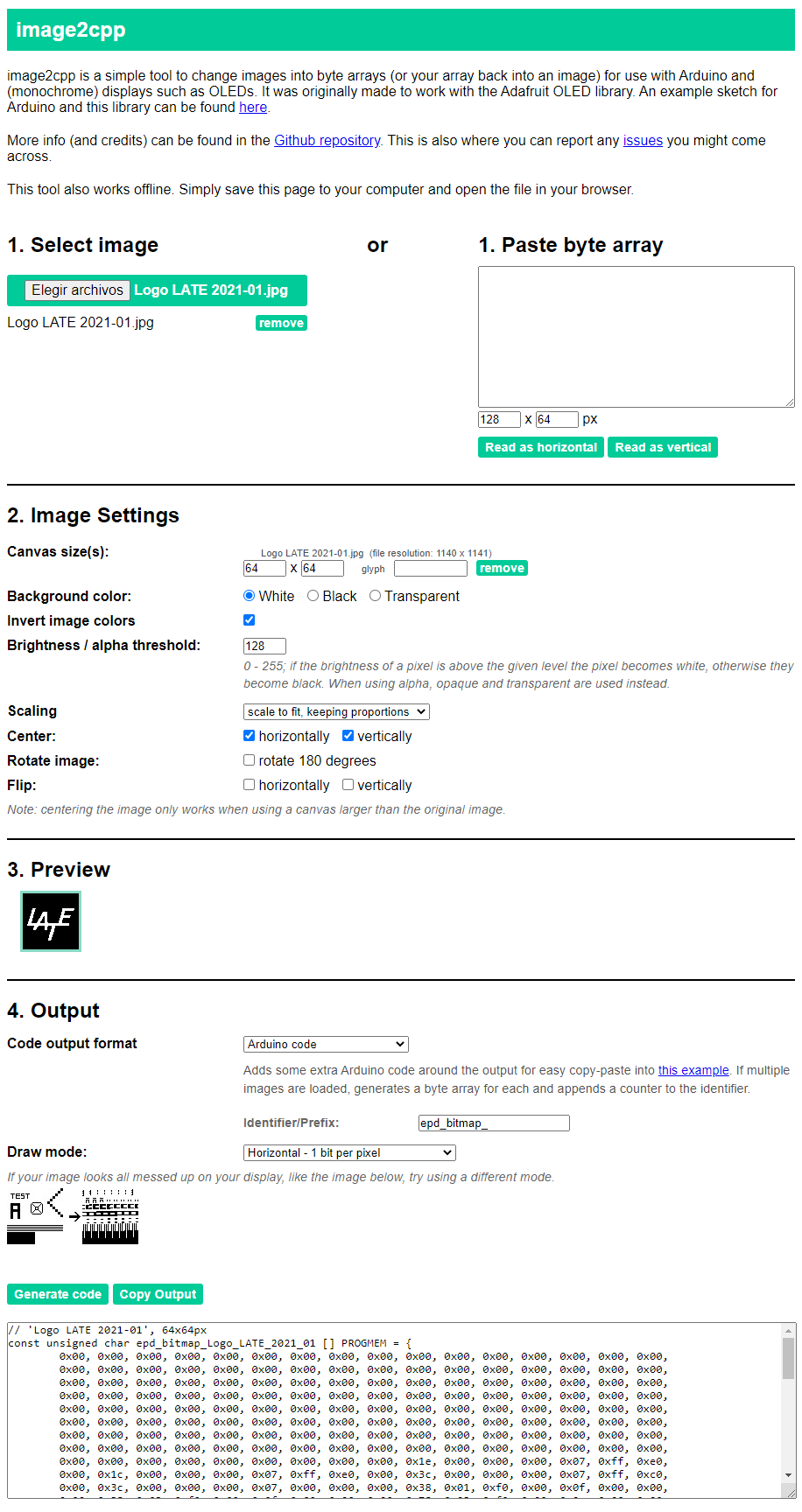
Then I open this code provided by my instructor Rodrigo Shiordia in order to personalize the image in the screen. I processed the image with the logo of my lab by uploading a jpg (first tried png and didn’t work) image into this page using the following parameters:
-
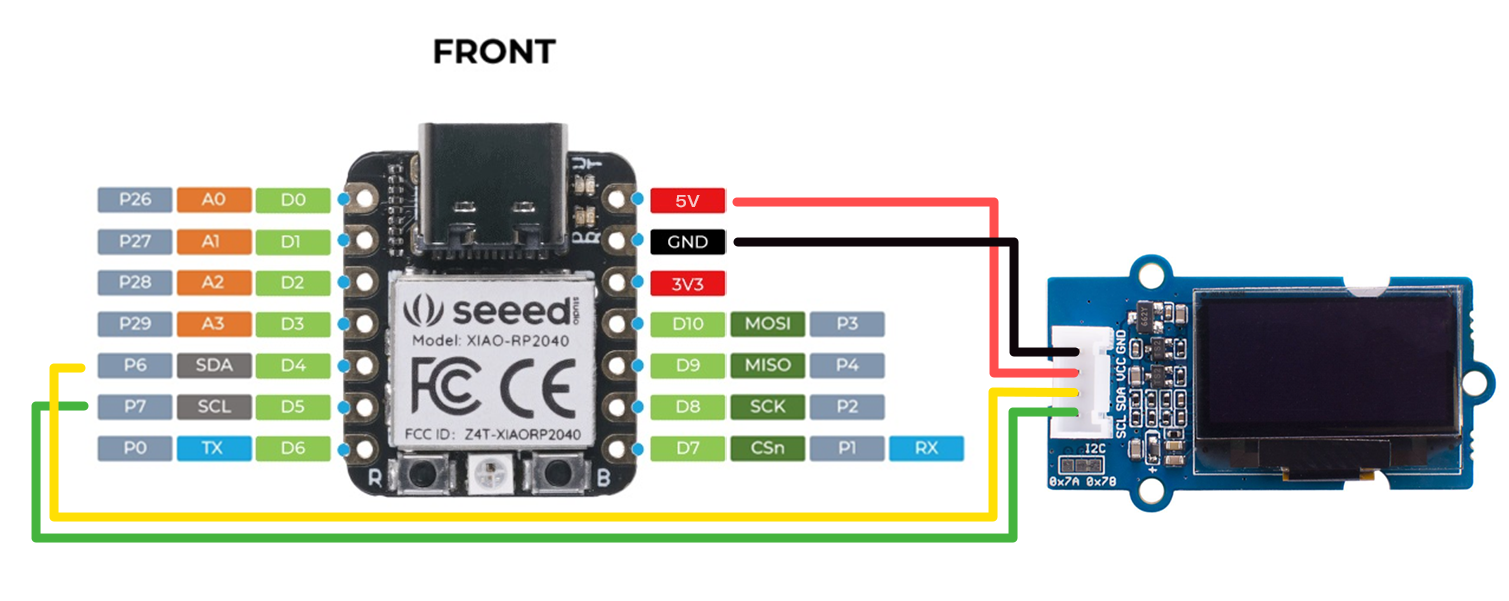
Copied the values obtained into the code. Then I connected the display by following this diagram:
-
Uploaded the code, and ready! I had my logo on the screen
-
This is how the code ended:
    /**************************************************************************
      This is an example for our Monochrome OLEDs based on SSD1306 drivers

      Pick one up today in the adafruit shop!
      ------> http://www.adafruit.com/category/63_98

      This example is for a 128x64 pixel display using I2C to communicate
      3 pins are required to interface (two I2C and one reset).

      Adafruit invests time and resources providing this open
      source code, please support Adafruit and open-source
      hardware by purchasing products from Adafruit!

      Written by Limor Fried/Ladyada for Adafruit Industries,
      with contributions from the open source community.
      BSD license, check license.txt for more information
      All text above, and the splash screen below must be
      included in any redistribution.
    **************************************************************************/

    #include <SPI.h>
    #include <Wire.h>
    #include <Adafruit_GFX.h>
    #include <Adafruit_SSD1306.h>

    #define SCREEN_WIDTH 128 // OLED display width, in pixels
    #define SCREEN_HEIGHT 64 // OLED display height, in pixels

    // Declaration for an SSD1306 display connected to I2C (SDA, SCL pins)
    // The pins for I2C are defined by the Wire-library.
    // On an arduino UNO:       A4(SDA), A5(SCL)
    // On an arduino MEGA 2560: 20(SDA), 21(SCL)
    // On an arduino LEONARDO:   2(SDA),  3(SCL), ...
    #define OLED_RESET     4 // Reset pin # (or -1 if sharing Arduino reset pin)
    #define SCREEN_ADDRESS 0x3C ///< See datasheet for Address; 0x3D for 128x64, 0x3C for 128x32
    Adafruit_SSD1306 display(SCREEN_WIDTH, SCREEN_HEIGHT, &Wire, OLED_RESET);

    #define NUMFLAKES     1 // Number of snowflakes in the animation example

    #define LOGO_HEIGHT   64
    #define LOGO_WIDTH    64

    // 'Fab_Lab_logo-01', 64x64px
    //// 'Logo LATE 2021-01', 64x64px
    const unsigned char epd_bitmap_Logo_LATE_2021_01 [] PROGMEM = {
      0x00, 0x00, 0x00, 0x00, 0x00, 0x00, 0x00, 0x00, 0x00, 0x00, 0x00, 0x00, 0x00, 0x00, 0x00, 0x00,
      0x00, 0x00, 0x00, 0x00, 0x00, 0x00, 0x00, 0x00, 0x00, 0x00, 0x00, 0x00, 0x00, 0x00, 0x00, 0x00,
      0x00, 0x00, 0x00, 0x00, 0x00, 0x00, 0x00, 0x00, 0x00, 0x00, 0x00, 0x00, 0x00, 0x00, 0x00, 0x00,
      0x00, 0x00, 0x00, 0x00, 0x00, 0x00, 0x00, 0x00, 0x00, 0x00, 0x00, 0x00, 0x00, 0x00, 0x00, 0x00,
      0x00, 0x00, 0x00, 0x00, 0x00, 0x00, 0x00, 0x00, 0x00, 0x00, 0x00, 0x00, 0x00, 0x00, 0x00, 0x00,
      0x00, 0x00, 0x00, 0x00, 0x00, 0x00, 0x00, 0x00, 0x00, 0x00, 0x00, 0x00, 0x00, 0x00, 0x00, 0x00,
      0x00, 0x00, 0x00, 0x00, 0x00, 0x00, 0x00, 0x00, 0x00, 0x00, 0x00, 0x00, 0x00, 0x00, 0x00, 0x00,
      0x00, 0x00, 0x00, 0x00, 0x00, 0x00, 0x00, 0x00, 0x00, 0x00, 0x00, 0x00, 0x00, 0x00, 0x00, 0x00,
      0x00, 0x00, 0x00, 0x00, 0x00, 0x00, 0x00, 0x00, 0x00, 0x1e, 0x00, 0x00, 0x00, 0x07, 0xff, 0xe0,
      0x00, 0x1c, 0x00, 0x00, 0x00, 0x07, 0xff, 0xe0, 0x00, 0x3c, 0x00, 0x00, 0x00, 0x07, 0xff, 0xc0,
      0x00, 0x3c, 0x00, 0x00, 0x00, 0x07, 0x00, 0x00, 0x00, 0x38, 0x01, 0xf0, 0x00, 0x0f, 0x00, 0x00,
      0x00, 0x38, 0x03, 0xf0, 0x00, 0x0f, 0x00, 0x00, 0x00, 0x78, 0x03, 0xf0, 0x00, 0x0e, 0x00, 0x00,
      0x00, 0x70, 0x07, 0xf0, 0x00, 0x0e, 0x00, 0x00, 0x00, 0x70, 0x07, 0xf0, 0x00, 0x1f, 0xfe, 0x00,
      0x00, 0xf0, 0x0f, 0x70, 0x00, 0x1f, 0xfc, 0x00, 0x00, 0xf0, 0x0e, 0x70, 0x00, 0x1f, 0xfc, 0x00,
      0x00, 0xe0, 0x1e, 0x70, 0x00, 0x3c, 0x00, 0x00, 0x01, 0xe0, 0x3c, 0x70, 0x00, 0x3c, 0x00, 0x00,
      0x01, 0xe0, 0x3c, 0x70, 0x00, 0x38, 0x00, 0x00, 0x01, 0xe0, 0x78, 0x70, 0x00, 0x78, 0x00, 0x00,
      0x03, 0xc0, 0x70, 0x70, 0x00, 0x78, 0x00, 0x00, 0x03, 0xc0, 0xf0, 0x78, 0x00, 0x78, 0x00, 0x00,
      0x03, 0xff, 0xff, 0xff, 0xff, 0xff, 0xf8, 0x00, 0x07, 0xff, 0xff, 0xff, 0xff, 0xff, 0xf8, 0x00,
      0x07, 0xff, 0xff, 0xff, 0xff, 0xff, 0xf8, 0x00, 0x00, 0x07, 0xc0, 0x78, 0x78, 0x00, 0x00, 0x00,
      0x00, 0x07, 0x80, 0x70, 0x78, 0x00, 0x00, 0x00, 0x00, 0x0f, 0x00, 0x70, 0x78, 0x00, 0x00, 0x00,
      0x00, 0x0f, 0x00, 0x70, 0x70, 0x00, 0x00, 0x00, 0x00, 0x0e, 0x00, 0x70, 0xf0, 0x00, 0x00, 0x00,
      0x00, 0x00, 0x00, 0x00, 0xf0, 0x00, 0x00, 0x00, 0x00, 0x00, 0x00, 0x00, 0xf0, 0x00, 0x00, 0x00,
      0x00, 0x00, 0x00, 0x01, 0xe0, 0x00, 0x00, 0x00, 0x00, 0x00, 0x00, 0x01, 0xe0, 0x00, 0x00, 0x00,
      0x00, 0x00, 0x00, 0x01, 0xe0, 0x00, 0x00, 0x00, 0x00, 0x00, 0x00, 0x03, 0xc0, 0x00, 0x00, 0x00,
      0x00, 0x00, 0x00, 0x03, 0xc0, 0x00, 0x00, 0x00, 0x00, 0x00, 0x00, 0x03, 0xc0, 0x00, 0x00, 0x00,
      0x00, 0x00, 0x00, 0x03, 0x80, 0x00, 0x00, 0x00, 0x00, 0x00, 0x00, 0x07, 0x80, 0x00, 0x00, 0x00,
      0x00, 0x00, 0x00, 0x07, 0x80, 0x00, 0x00, 0x00, 0x00, 0x00, 0x00, 0x07, 0x00, 0x00, 0x00, 0x00,
      0x00, 0x00, 0x00, 0x00, 0x00, 0x00, 0x00, 0x00, 0x00, 0x00, 0x00, 0x00, 0x00, 0x00, 0x00, 0x00,
      0x00, 0x00, 0x00, 0x00, 0x00, 0x00, 0x00, 0x00, 0x00, 0x00, 0x00, 0x00, 0x00, 0x00, 0x00, 0x00,
      0x00, 0x00, 0x00, 0x00, 0x00, 0x00, 0x00, 0x00, 0x00, 0x00, 0x00, 0x00, 0x00, 0x00, 0x00, 0x00,
      0x00, 0x00, 0x00, 0x00, 0x00, 0x00, 0x00, 0x00, 0x00, 0x00, 0x00, 0x00, 0x00, 0x00, 0x00, 0x00,
      0x00, 0x00, 0x00, 0x00, 0x00, 0x00, 0x00, 0x00, 0x00, 0x00, 0x00, 0x00, 0x00, 0x00, 0x00, 0x00
    };

    int x = 0;

    void setup() {
      Serial.begin(9600);

      // SSD1306_SWITCHCAPVCC = generate display voltage from 3.3V internally
      if (!display.begin(SSD1306_SWITCHCAPVCC, SCREEN_ADDRESS)) {
        Serial.println(F("SSD1306 allocation failed"));
        for (;;); // Don't proceed, loop forever
      }
    }

    void loop() {
      // Clear the buffer
      //display.clearDisplay();
      // Draw a single pixel in white
      for (int i = 0; i < SCREEN_HEIGHT; i++) {
        display.drawPixel(x, i, SSD1306_WHITE);
      }
      // Show the display buffer on the screen. You MUST call display() after
      // drawing commands to make them visible on screen!
      display.display();
      x++;
      delay(2);
      if (x > SCREEN_WIDTH) {
        testdrawbitmap();
        delay(5000);
        display.clearDisplay();
        x = 0;
      }
  }

    void testdrawbitmap(void) {
      display.clearDisplay();

      display.drawBitmap(
        (display.width()  - LOGO_WIDTH ) / 2,
        (display.height() - LOGO_HEIGHT) / 2,
        epd_bitmap_Logo_LATE_2021_01, LOGO_WIDTH, LOGO_HEIGHT, 1);
      display.display();
      delay(1000);
    }
Seeed XIAO ESP32C3
-
In order to connect this other MCU I followed instructions on this page Getting Started with Seeed Studio XIAO ESP32C3
-
Connect the Seeed Studio XIAO ESP32C3 to the PC. In my case I heard the typical USB connection sound on Windows.
-
Launch the Arduino application and Add Seeed Studio XIAO RP2040 board package to your Arduino IDE, by navigating to File > Preferences, and fill Additional Boards Manager URLs with the url below:
https://raw.githubusercontent.com/espressif/arduino-esp32/gh-pages/package_esp32_dev_index.json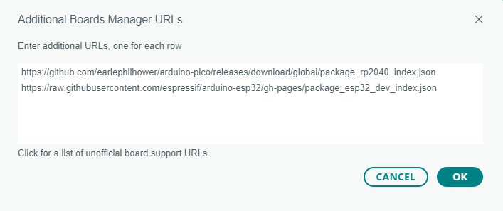
-
Navigate to Tools-> Board-> Boards Manager…, type the keyword “esp32” in the searching blank. select the latest version of *esp32*, and install it. (I had to try twice, the first attempt to install failed, the second was ok)

-
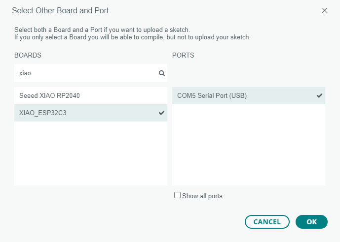
Select your board and port.
-
Followed the next wiring
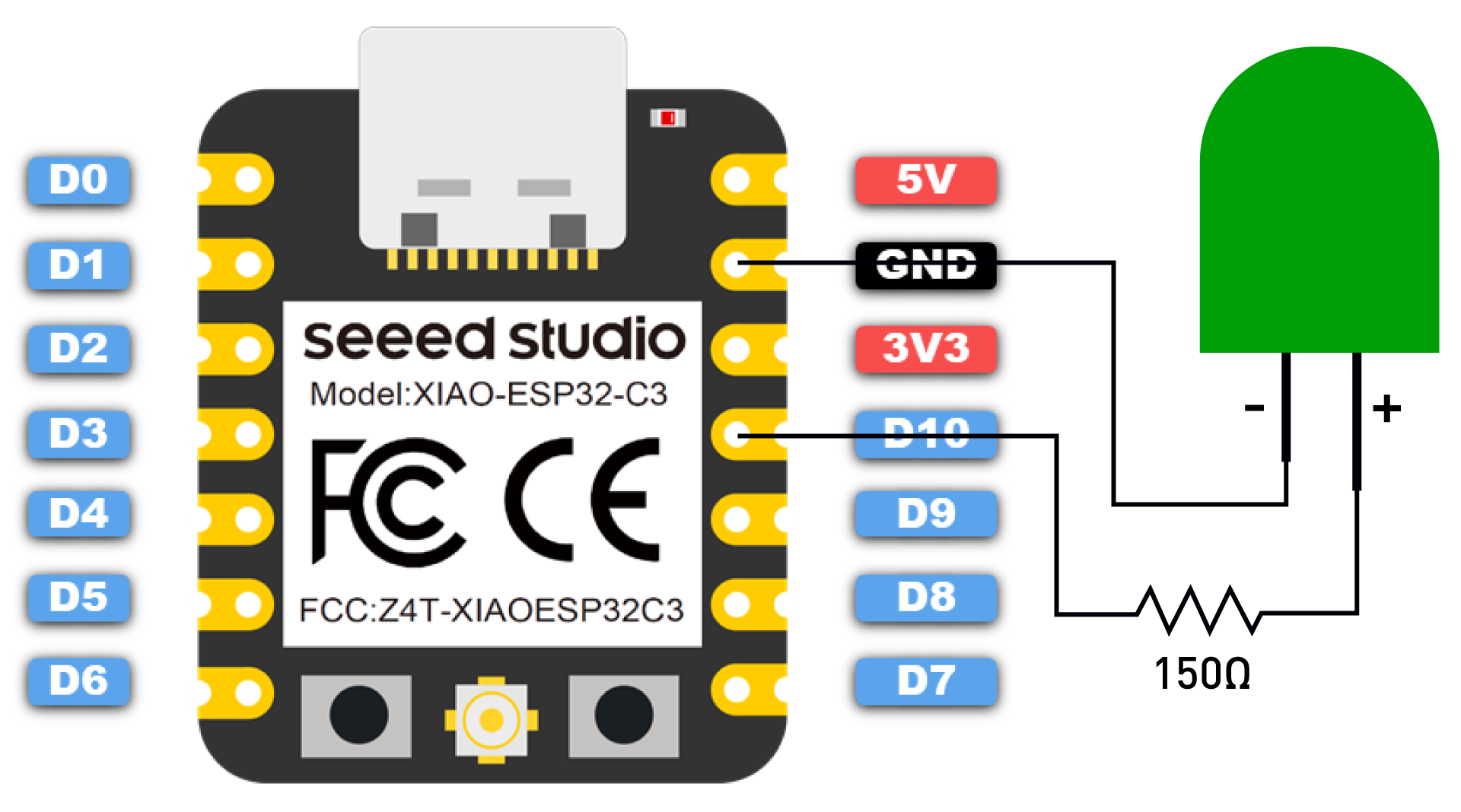
-
I copied the following code and pressed the upload button, waited for some process to carry out and then the LED started blinking
  // define led according to pin diagram
    int led = D10;

    void setup() {
      // initialize digital pin led as an output
      pinMode(led, OUTPUT);
    }

    void loop() {
      digitalWrite(led, HIGH);   // turn the LED on
      delay(1000);               // wait for a second
      digitalWrite(led, LOW);    // turn the LED off
      delay(1000);               // wait for a second
    }
Seeed XIAO ESP32C3 wifi usage
-
In order to seek the use of this characteristic I followed instructions on this page Seeed Studio XIAO ESP32C3WiFi Usage on Seeed Studio XIAO ESP32C3
-
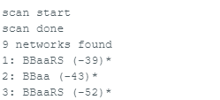
First we should scan available WiFi networks around with the following code
#include "WiFi.h"

void setup()
{
    Serial.begin(115200);

    // Set WiFi to station mode and disconnect from an AP if it was previously connected
    WiFi.mode(WIFI_STA);
    WiFi.disconnect();
    delay(100);

    Serial.println("Setup done");
}

void loop()
{
    Serial.println("scan start");

    // WiFi.scanNetworks will return the number of networks found
    int n = WiFi.scanNetworks();
    Serial.println("scan done");
    if (n == 0) {
        Serial.println("no networks found");
    } else {
        Serial.print(n);
        Serial.println(" networks found");
        for (int i = 0; i < n; ++i) {
            // Print SSID and RSSI for each network found
            Serial.print(i + 1);
            Serial.print(": ");
            Serial.print(WiFi.SSID(i));
            Serial.print(" (");
            Serial.print(WiFi.RSSI(i));
            Serial.print(")");
            Serial.println((WiFi.encryptionType(i) == WIFI_AUTH_OPEN)?" ":"*");
            delay(10);
        }
    }
    Serial.println("");

    // Wait a bit before scanning again
    delay(5000);
}
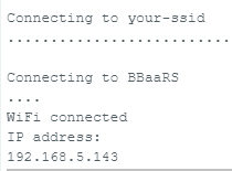
Connect XIAO ESP32C3 to Wifi network
- XIAO ESP32C3 can connect to a WiFI network with the following code
#include <WiFi.h>

const char* ssid     = "your-ssid";
const char* password = "your-password";

void setup()
{
    Serial.begin(115200);
    delay(10);

    // We start by connecting to a WiFi network

    Serial.println();
    Serial.println();
    Serial.print("Connecting to ");
    Serial.println(ssid);

    WiFi.begin(ssid, password);

    while (WiFi.status() != WL_CONNECTED) {
        delay(500);
        Serial.print(".");
    }

    Serial.println("");
    Serial.println("WiFi connected");
    Serial.println("IP address: ");
    Serial.println(WiFi.localIP());
}
void loop()
{
  }
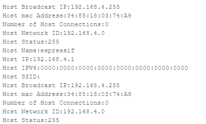
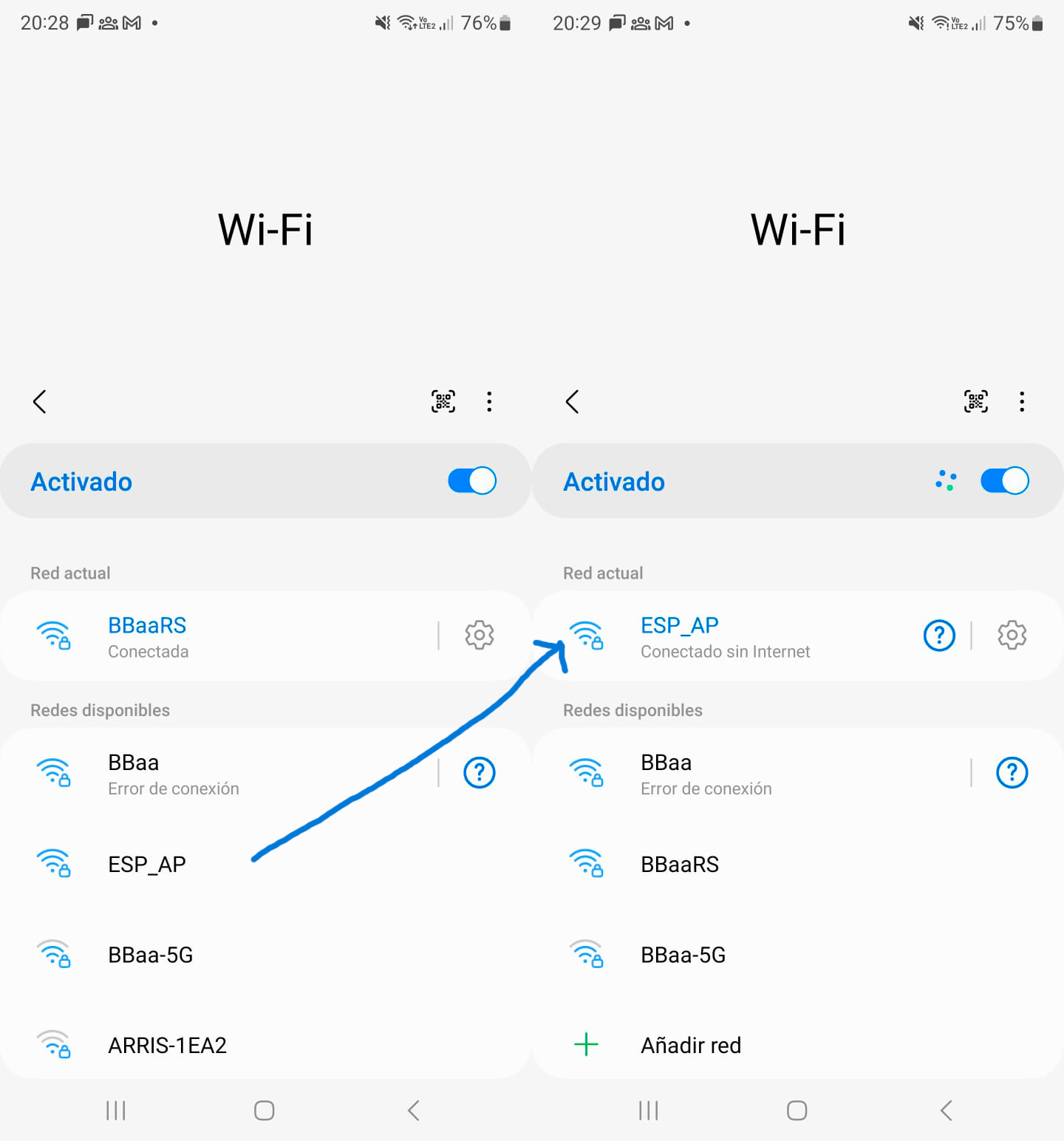
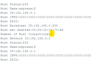
XIAO ESP32C3 as access point
- XIAO ESP32C3 may allow access to wifi with the following code
#include "WiFi.h"
void setup()
{
  Serial.begin(115200);
  WiFi.softAP("ESP_AP", "123456789");
}

void loop()
{
  Serial.print("Host Name:");
  Serial.println(WiFi.softAPgetHostname());
  Serial.print("Host IP:");
  Serial.println(WiFi.softAPIP());
  Serial.print("Host IPV6:");
  Serial.println(WiFi.softAPIPv6());
  Serial.print("Host SSID:");
  Serial.println(WiFi.SSID());
  Serial.print("Host Broadcast IP:");
  Serial.println(WiFi.softAPBroadcastIP());
  Serial.print("Host mac Address:");
  Serial.println(WiFi.softAPmacAddress());
  Serial.print("Number of Host Connections:");
  Serial.println(WiFi.softAPgetStationNum());
  Serial.print("Host Network ID:");
  Serial.println(WiFi.softAPNetworkID());
  Serial.print("Host Status:");
  Serial.println(WiFi.status());
  delay(1000);
}
Arduino MKR WIFI 1010 + MKR Relay Shield
I started getting acquainted with this MCU by following some first steps in here: Introduction
To open one relay then the other alternating with 1 second of difference and showing this by ligthing one or other led, I used this wiring diagram and code:
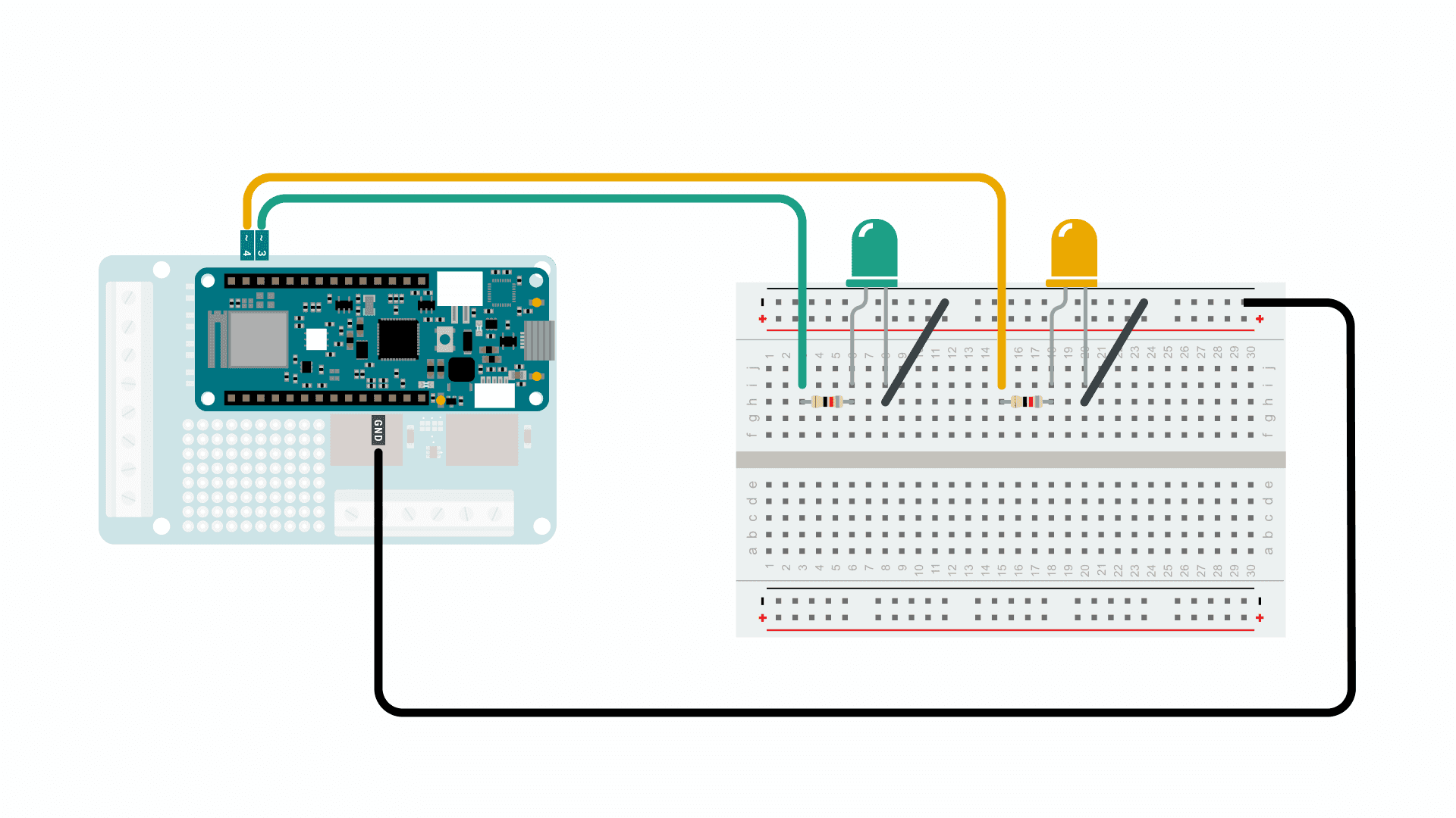
int relay_1 = 1;
int relay_2 = 2;

int LED_1 = 3;
int LED_2 = 4;

void setup() {

pinMode(relay_1, OUTPUT);
pinMode(relay_2, OUTPUT);
pinMode(LED_1, OUTPUT);
pinMode(LED_2, OUTPUT);

}

void loop() {

digitalWrite(relay_1, HIGH);
digitalWrite(LED_1, HIGH);
digitalWrite(relay_2, LOW);
digitalWrite(LED_2, LOW);

delay(1000);

digitalWrite(relay_1, LOW);
digitalWrite(LED_1, LOW);
digitalWrite(relay_2, HIGH);
digitalWrite(LED_2, HIGH);

delay(1000);

}
Arduino MKR WIFI 1010 + MKR Relay Shield GOAL: switching on and off from keyboard
I set as a personal goal to program individually, the turning on and off of a 9V powered motor (on my way to higher voltages) with a relay on the MKR shield.
I developed the following code with the aid of my instructor:
int relay_1 = 1; //relay 1 is preasigned to pin 1 on this board
int LED_1 = 3;
char varc = 0;

void setup() {
Serial.begin(9600);
pinMode(relay_1, OUTPUT);
pinMode(LED_1, OUTPUT);
}

void loop() {
while (Serial.available()>0){
  varc = Serial.read ();
  if (varc == 'A'){
    //do something
    digitalWrite(relay_1, HIGH);
    digitalWrite(LED_1, HIGH);
    Serial.print("| off · apagado ");
  }
  else if (varc == 'P'){
    //do something
    digitalWrite(relay_1, LOW);
    digitalWrite(LED_1, LOW);
    Serial.print("| on · prendido ");
  }
}
}