12. Machine Design
Week 12 · 2023.04.05-2023.04.12
This past two weeks we’ve being into developing an extruder for biomaterials with a robotic arm. We divided work as follows: The electronics and step-motor are in charge of Judy (my colleague) and the geometry and its general assembly are in charge of me.
- [x] Documented the machine building process to the group page
- [x] Documented your individual contribution to this project on your own website
- [x] Linked to the group page from your individual page as well as from group page to your individual pages
- [x] Shown how your team planned and executed the project (Group page)
- [x] Described problems and how the team solved them (Group page)
- [x] Listed future development opportunities for this project (Group page)
- [x] Included your design files (Group page)
- [x] You need to present your machine globally and/or include an aprox. 1 min video (1920x1080 HTML5 MP4) + slide (1920x1080 PNG) (Group page)
Design Process
We wanted to build a simple machine with a step motor and having in account the past experiences of our tutor, and our converging interests in extruding materials, we thought it may be a good idea to do a 3d printed extruder.
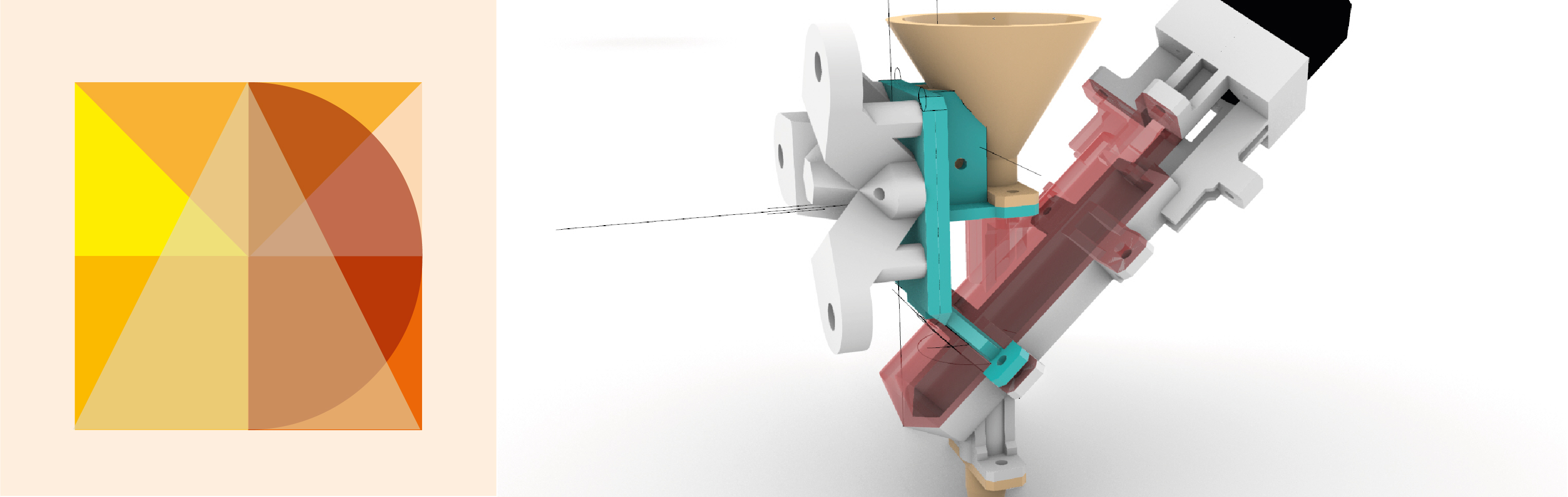
I Designed the parts based in previous examples such as Rodrigo Shiordia’s final project. I sketched the idea in Rhino and made some handwritten notes.
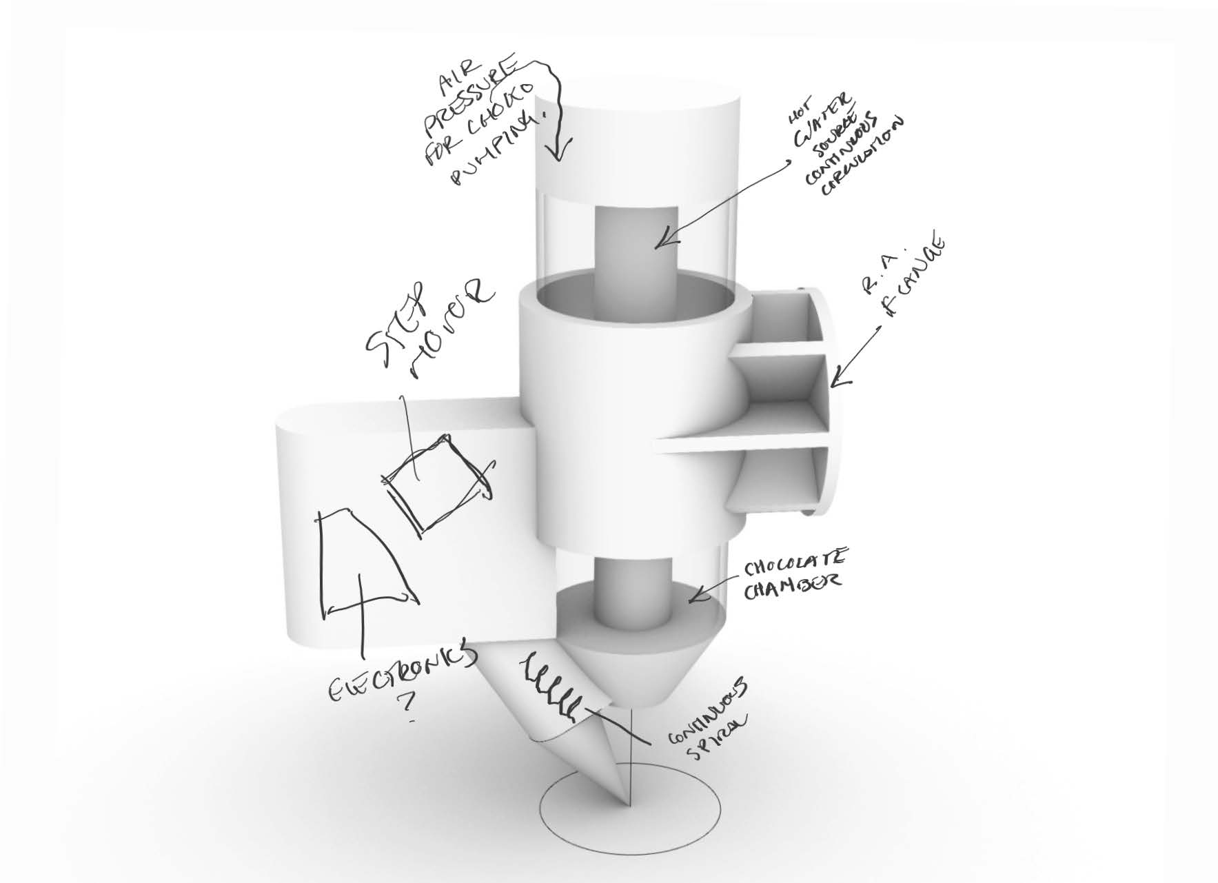
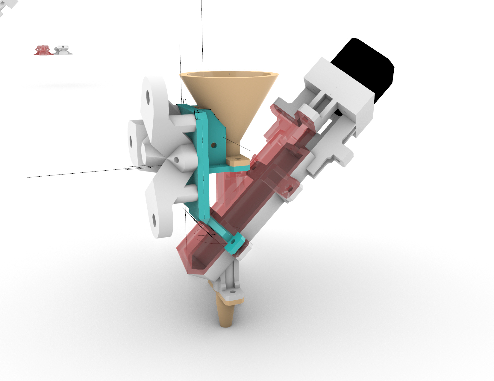
I produced a first sketch to see all the parts taking place and how would they relate between theme. For instance I wanted to tilt the continuous spiral rod, so it would shorten the whole extruder.
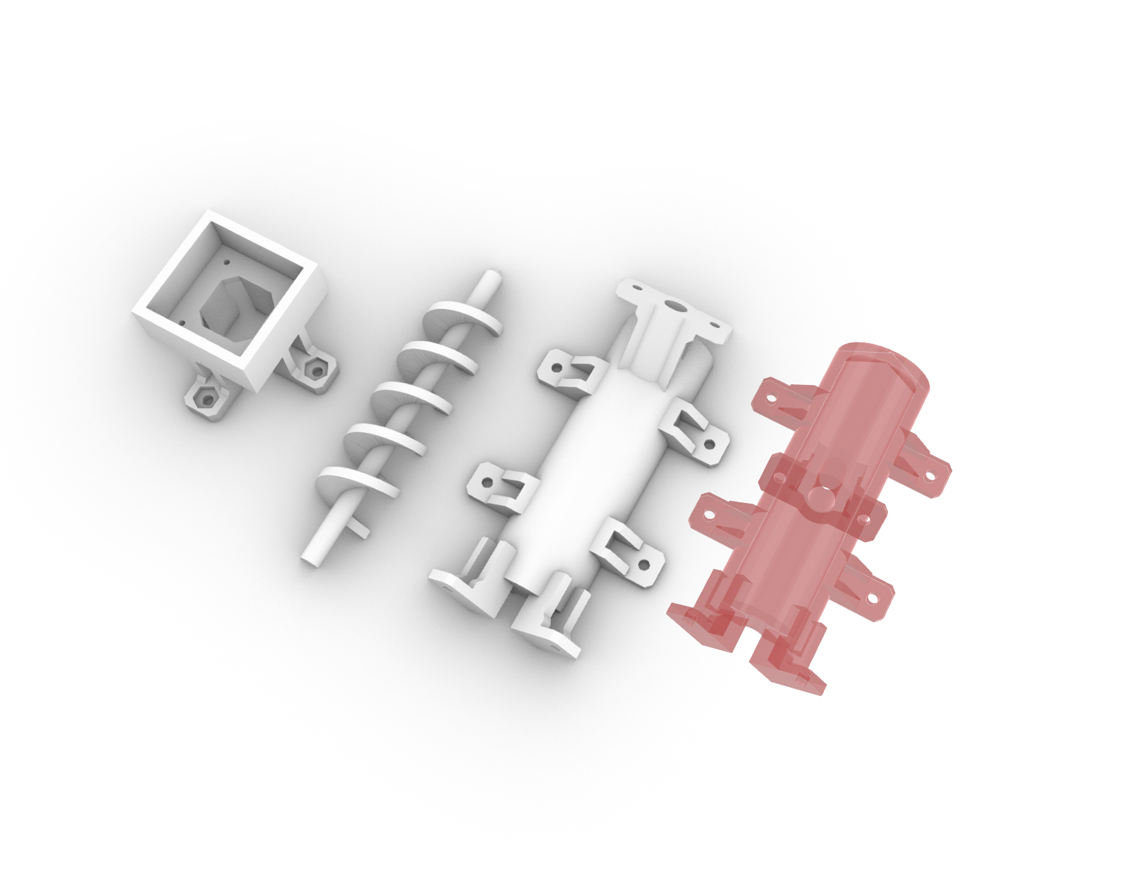
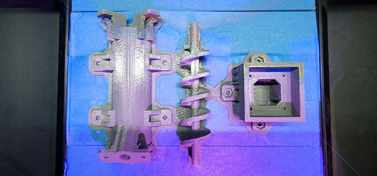
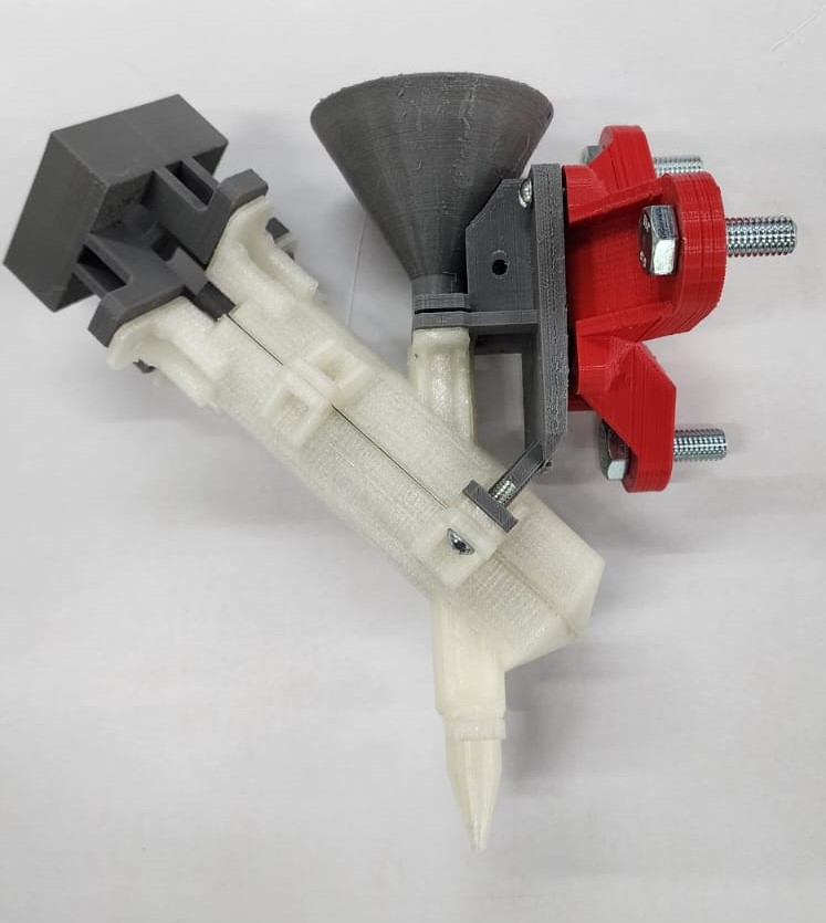
After some precautions I decided to divide the extruder in different pieces so it would be easier to 3dprint, it would be easier to clean and if the fabrication, design or coupling with the electronics and step motor failed or had a bigger issue I would be able to repeat the pieces or change them individually.
I started with the continous spiral rod, since it might be the most complex geometry, and defined how the chamber would surround the piece.
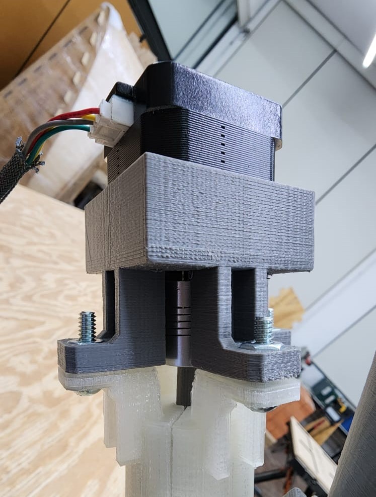
I did a model for the motor following the datasheet and came around a box that would fit it and allow attaching to the next piece with some screws.
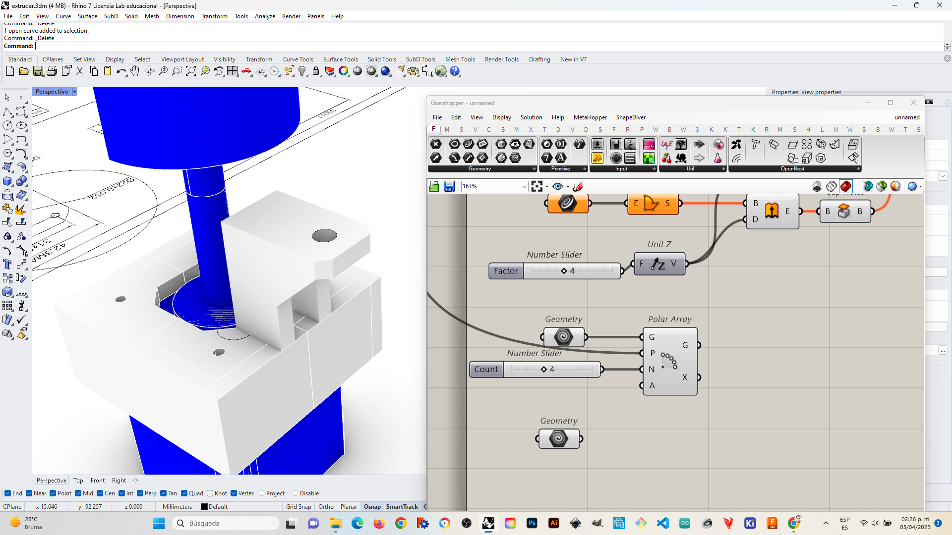
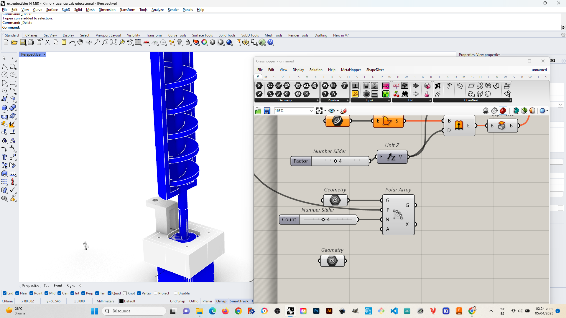
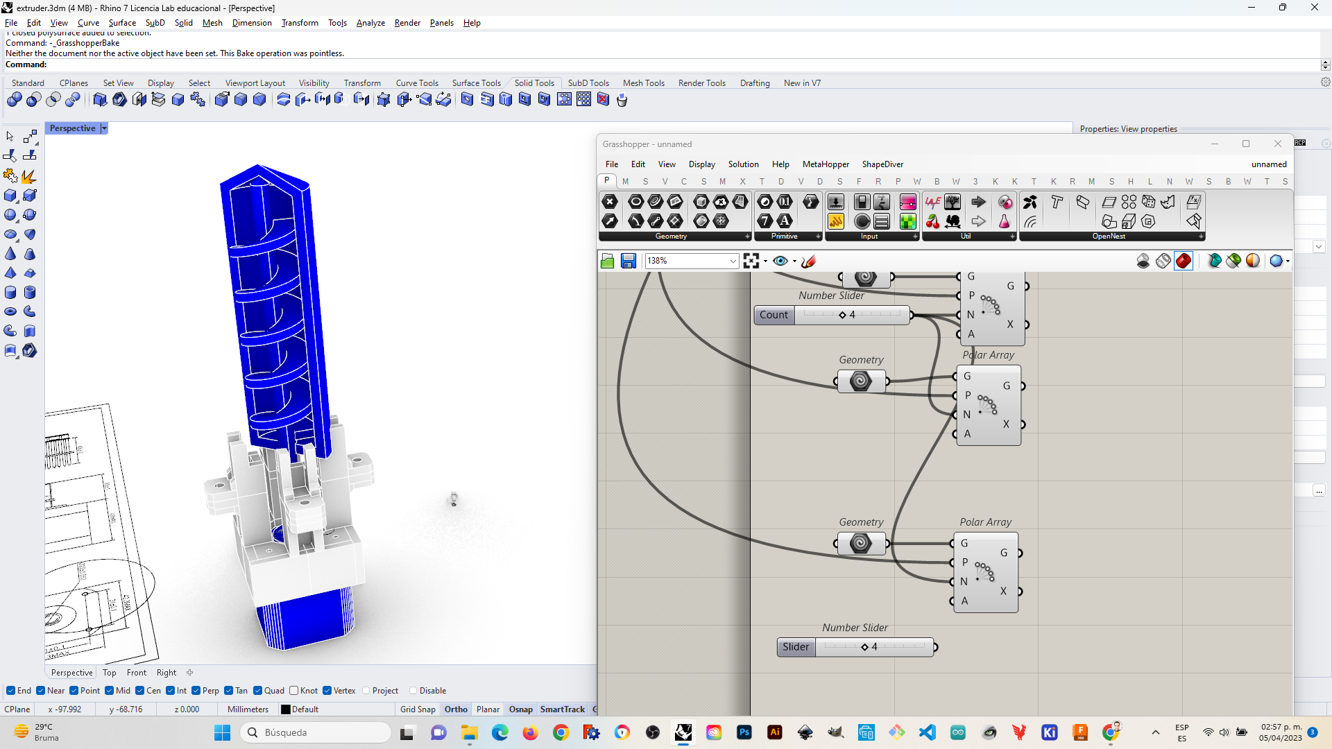
Whith a polar array I would be sure if it would be able to fix to the next piece while leaving enough room for motor rod, the spiral rod and the coupling between them.
Following this logic I incorporated the corresponding screw hole tabs for the other piece. This was the base for designing the following pieces.
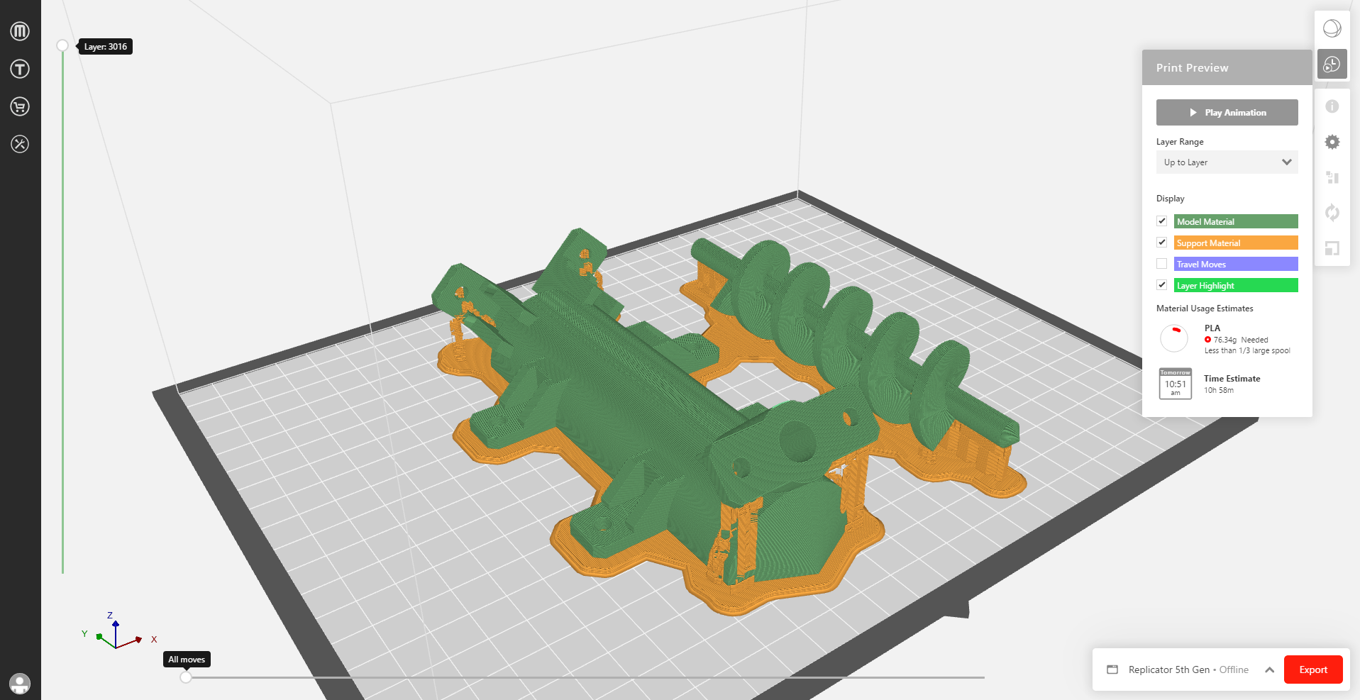
Also, the attachment to the robotic arm would be easier since I already had worked out the solution in previous designs. So I laid down the pieces for 3dprinting, postprocessed them with makerbot print and produced them between April 5 and 8.
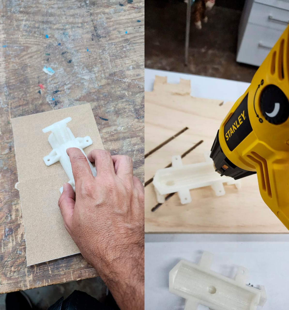
Since I had several issues with 3d prints such as warping I repeated (while improving) some pieces.
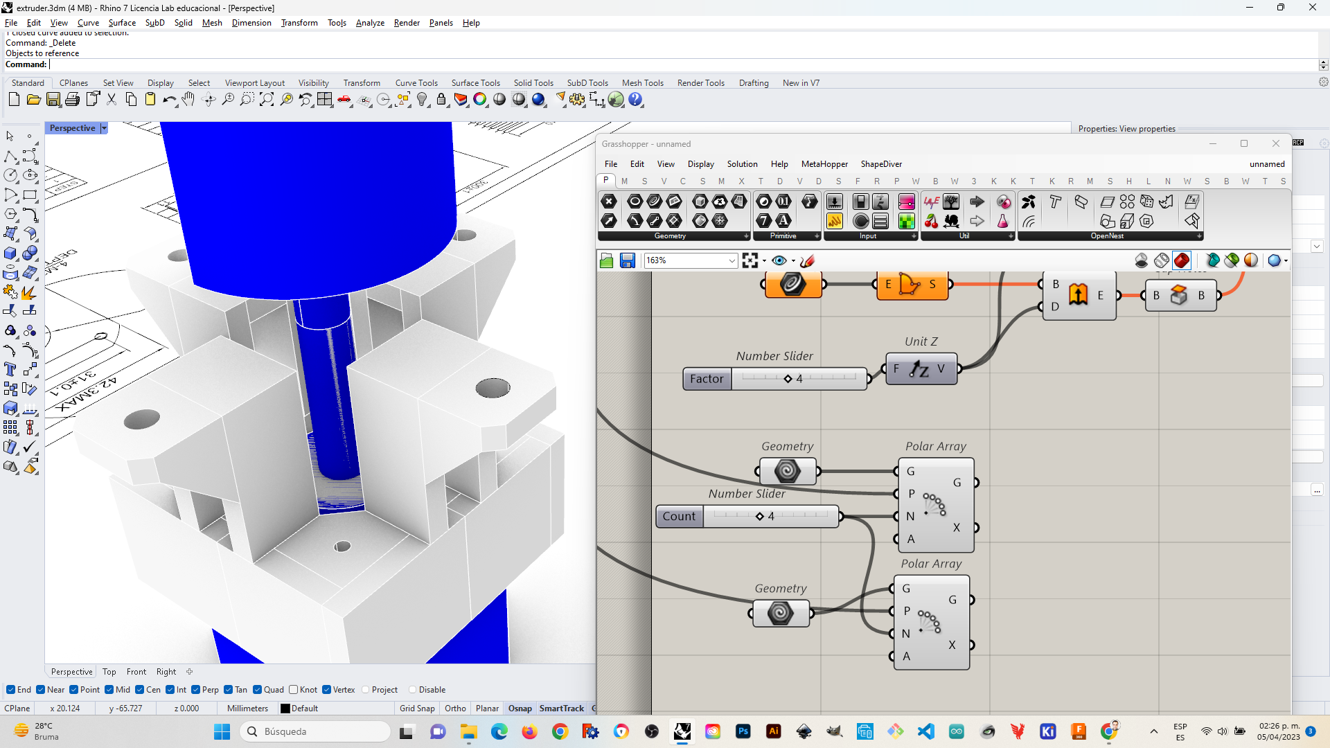
For the final design, I used Rhino with some aid of Grasshopper, postprocessed the geometry in Makerbot Print, and printed with two 3d printers. A makerbot 5G and a Makerbot Z18.
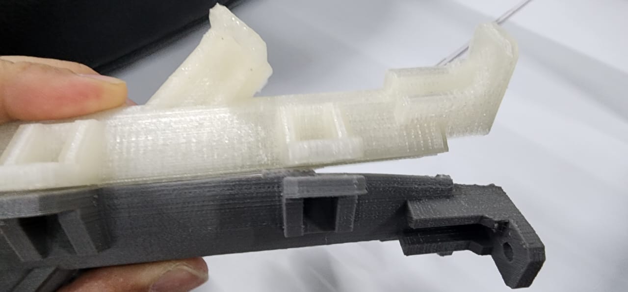
In order to improve a tight fitting between the two halves of the chamber I sanded the 3d prints, and even used a heatgun which did actually seal better but deformed somewhat the pieces.
I needed to be sure the final pieces had no problem with the continuous spiral rod rotating, so I did some tests with an impact wrench.
After coming up with different prints, and a couple of different nozzles, I started the first screwing attempt.
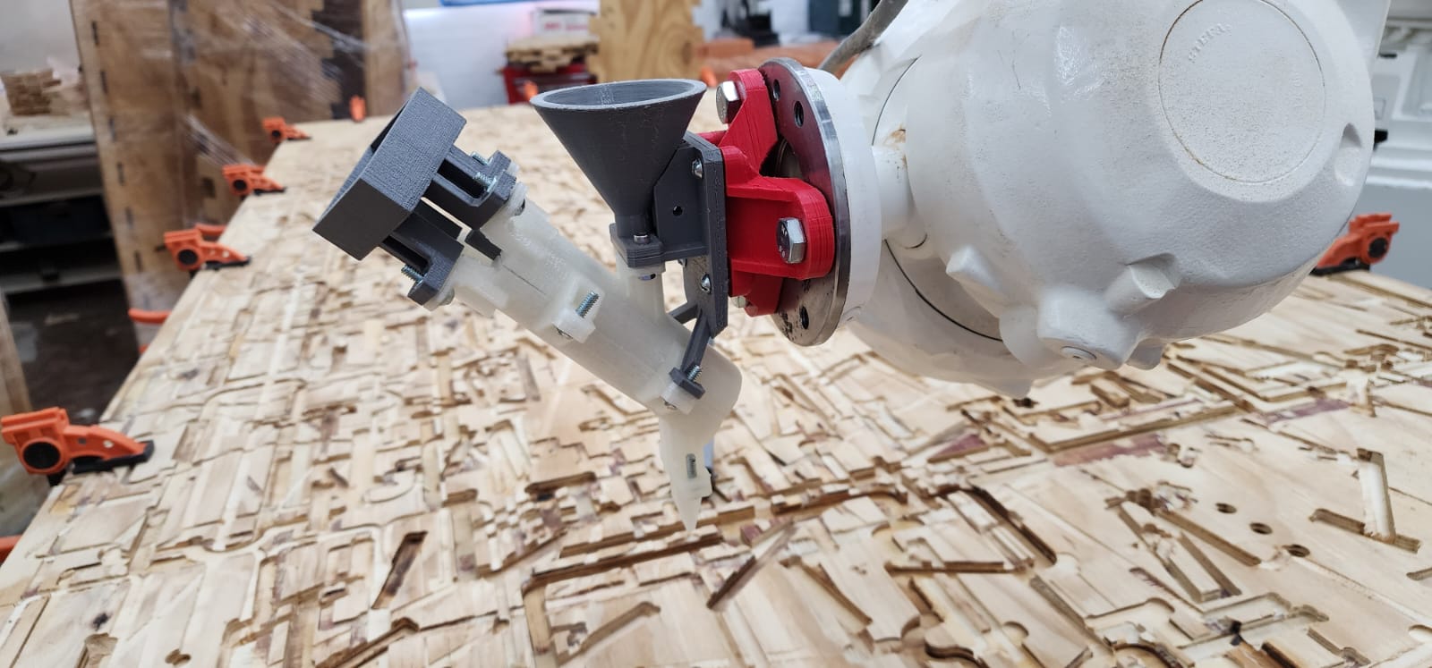
When everything proved to be quite alright, I attached to the robotic arm and it proved to be firmly attached.
Motor fitting and electronics
I tried to help oout with the pcb production of my colleague since she had several complications for producing this, and this proved not to be an exeption, it didn’ came out well.
We were able to see that the motor and the coupling were fitting quite well into my design.
The rise of the dripping machine
Following all the complications that led to not having the motor and electronics on time to fit into the extruder. I decided to test the extruder for a thinner material that may drop by gravity and then I came around with the idea to prove it with a pancake mix and have some sort of design to be developed by the robotic arm movement.
Additionally the mix would allow to try thinner or thicker mixes in order to see which performed best, and how ‘liquid tight’ were the 3d printed pieces behaving.
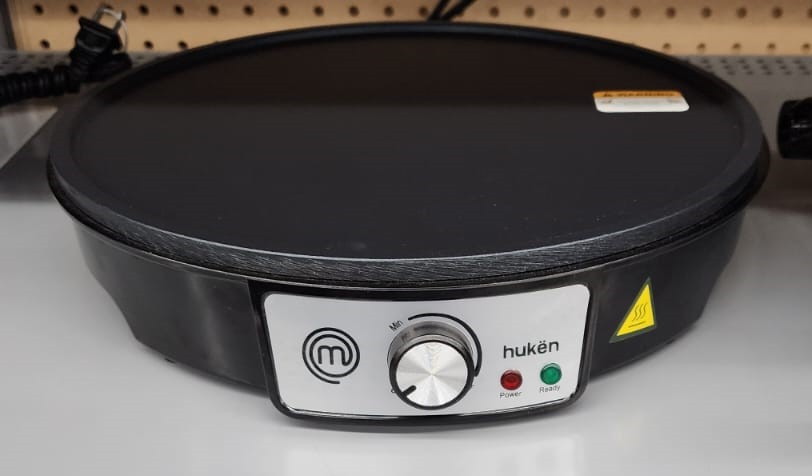
So I bought an electric pan for crepes and all the ingredients to make it happen.
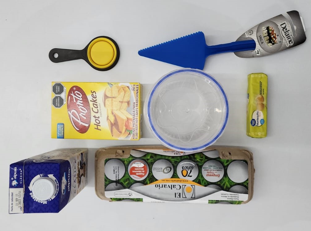
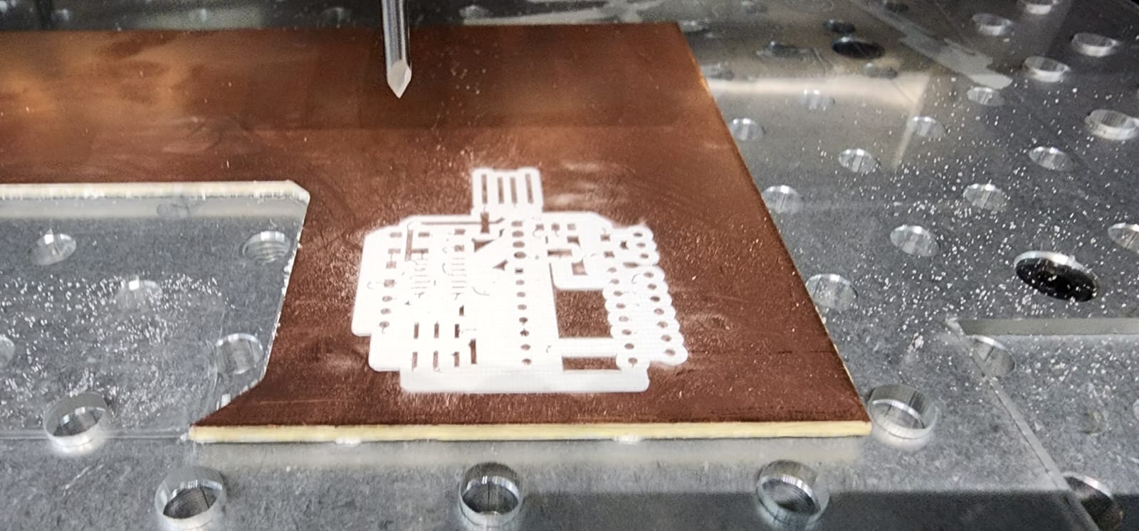
I edited the logo of the fablab in order to make it one single line, modeled the necessary items to get arround and programmed our robotic arm to follow the path. I came out with two scripts, one to place the electric pan with an outline of the hot-planar surface, and another with the fablab logo routing.
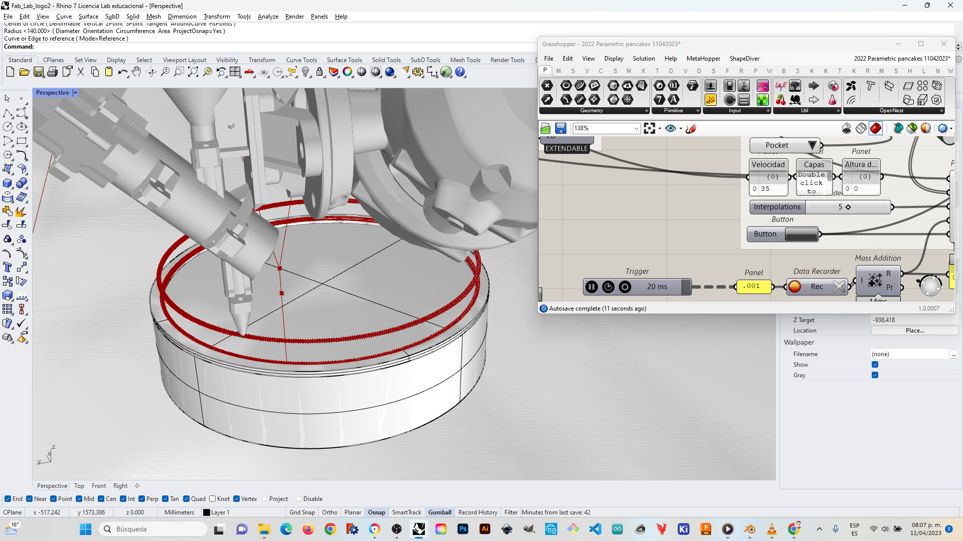
I simulated the rutes of the arm to see if everything was ok.
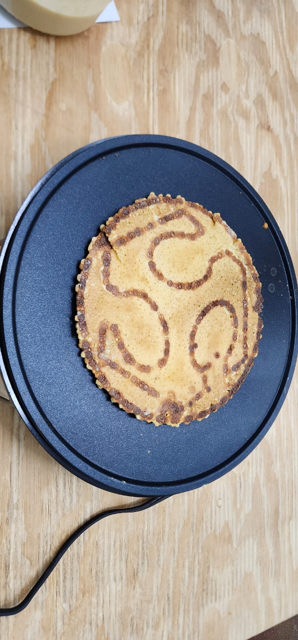
After taking in account how thick the mix was, I had to take actions to make it thicker so it wouldn’t pour so fast. Also after using the first nozzle I realized it didn’t work properly since it expelled to much liquid, so I changed the nozzle for the narrowest I had. In the meantime I realized that if it dripped small drops it would be easier to control.
After this I filled left spaces in between the outlines et voilà!!
Robotic arm programming code:
Circular outline files
Logo files