8. Computer controlled machining
Week 08 · 2023.03.08-2023.03.15
This week I worked on developing a large format (human scaled) design to be cut through a CNC router machine.
- [x] Linked to the group assignment page Fablab Ciudad de México Group Assignment Page
- [x] Documented how you designed your object (something big)
- [x] Documented how you made your CAM-toolpath
- [x] Documented how you made something BIG (setting up the machine, using fixings, testing joints, adjusting feeds and speeds, depth of cut etc.)
- [x] Described problems and how you fixed them
- [x] Included your design files and ‘hero shot’ of your final product
Big Design
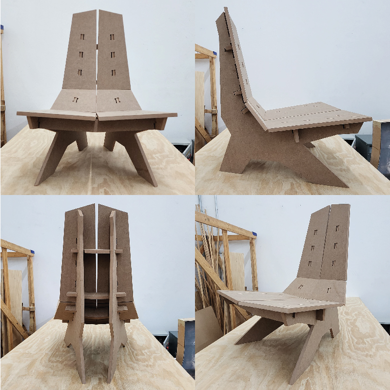
Since we had the assignment of ‘building big’ - this meaning a human scaled object - and taking in account that we were provided with a 4 by 8 feet MDF board, I decided to design and assemble a chair. My collateral objetives for this asignment were:
- Easy to assemble mostly by press fit
- Be able to fit the parts for transport (in my car)
- Assemble oblique parts with orthogonal cuts
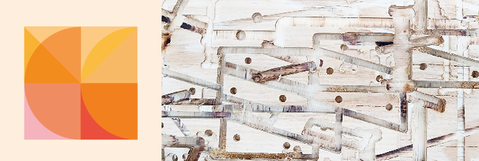
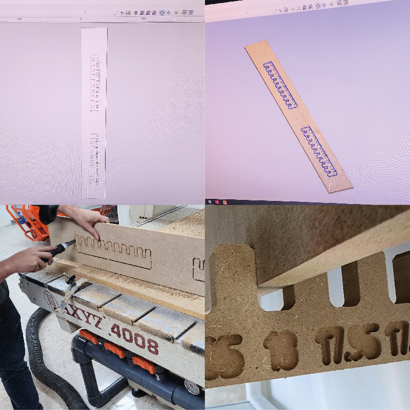
We started by understanding the width of the board, so I rescaled and adjusted the comb I used for the laser cut assignment. Starting on one side by 17.9mm and ending with 18.35mm on the other extreme in order to dimension proper tolerances.
Idea, Sketching and Design
I designed - according to the time I could put into design, mainly in CAD with somewhat assistance of some parametric processing in Grasshopper (normally I would do the whole thing in Grasshopper, but it demands more time)
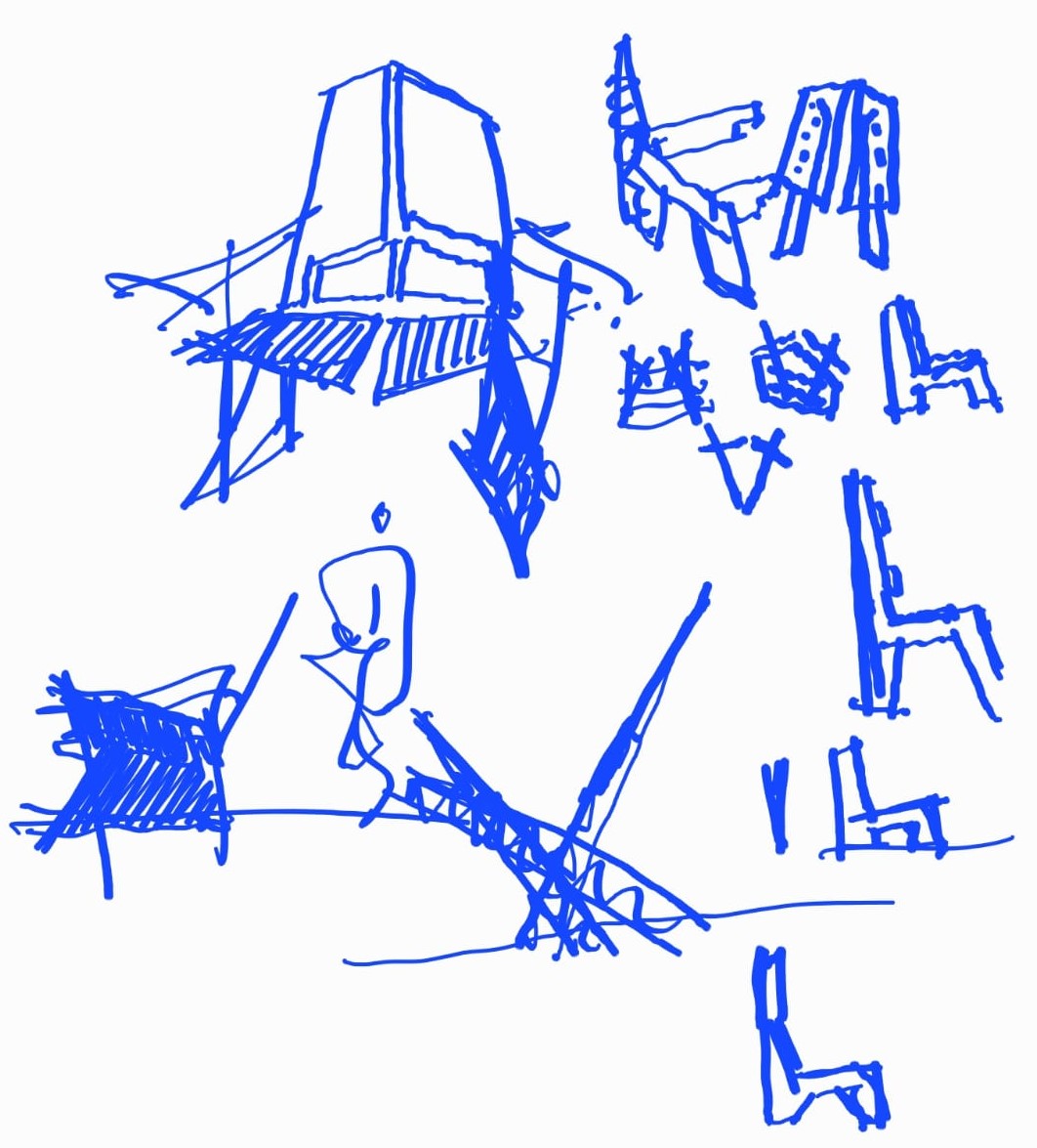
I started with some digital sketches then went into CAD.
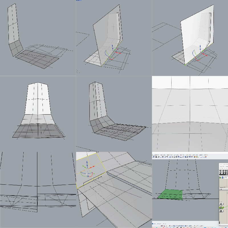
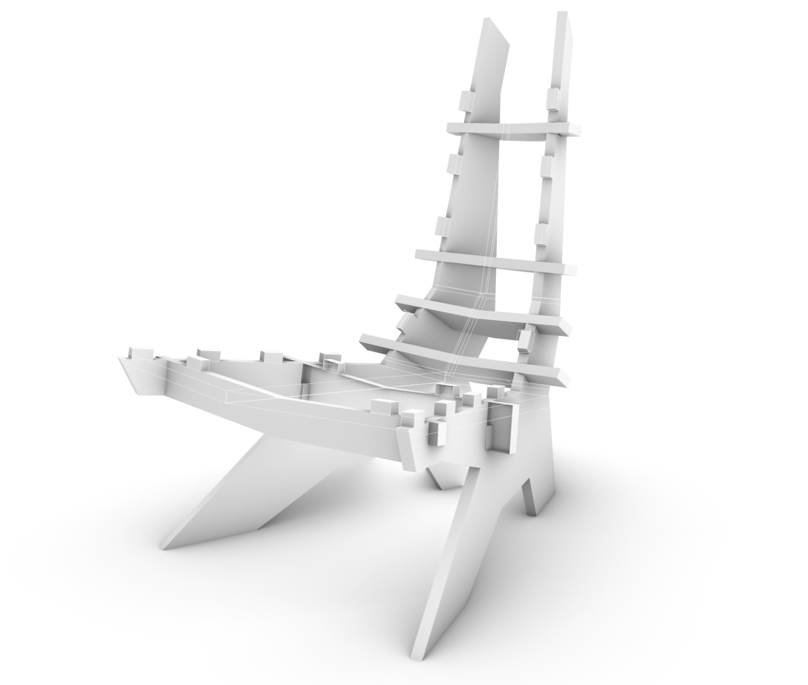
I started by drawing some lines in order to start settling the inclination of the back of the chair and the seat, then I turned them into surfaces and changed the height and the frontal contraction of the back.
I checked for simetry and was very careful not to go into double curvature surfaces which (according to my experience) would become difficult to deal with.
The I drew some lines to start understanding how the back ribs will develop, in terms of angles, and width vs strength.
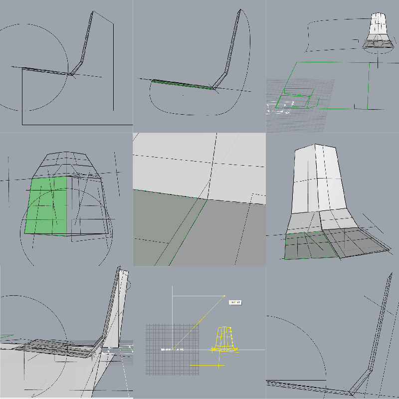
I set some variations for the back ribs, and then started converting to surfaces. It is important to take in account how much of the board it starts taking so you can be aware of how much is left and start negotiating some of the measurments so it will fully fit into the board.
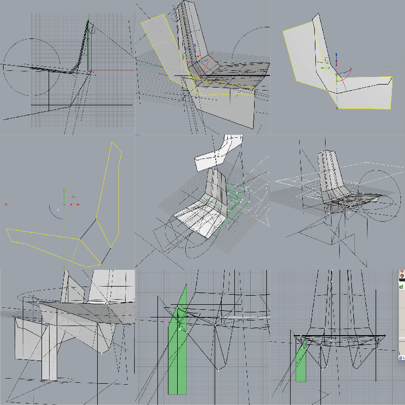
The development of the back ribs came out with some diagonals that fitted quite well also for being used as the support ribs for the seat. Then the process for the legs started, first as straights supports in a 90º angle (which I didn’t like much)
I started putting together (while taking design decisions) the seat ribs in the other direction, I decided that two ribs to support every important surface as the seat was enough. When I went for the second rib, close to the back of the seat, and found the right spot (it felt like this) I thought that probably there was no need to have double ribs for the long seat section and the legs, so I fused them in one and could easily pass the second rib. After having set the geometry I started placing the teeth that would press fit with the other boards.
Then I made several boolean operations so I would have the geometry in the right place. I redraw each part in order to have a clean rebuild for every part.
Whenever I couldn’t do the boolean operation (intersection built the joint to be taken of from one and the other piece crossing) I split one of the crossing geometries with triangular surfaces to get the ‘intersected geometries’ (that later on I found was not really a good way to go)
CNC Getting Acquainted and Safety Instructions
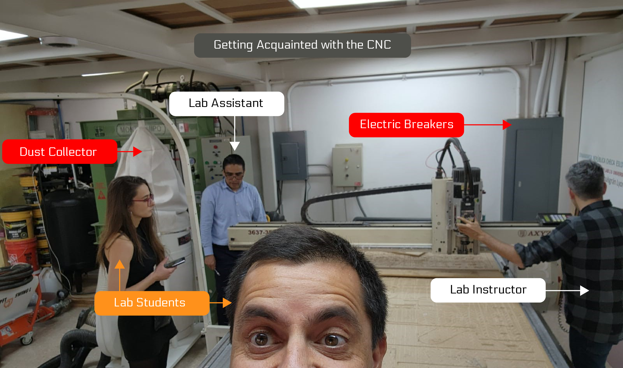
First we needed to know where the exits were, where the emergency stop buttons are, as well as the electric breakers (which are pretty close to the CNC).
- Be sure to have hair tied up, and no jewelery or loose clothing.
- Wear safety glasses (those that already use glasses should be usign protective glasses additionally as Neil stated in the revision of this assignment).
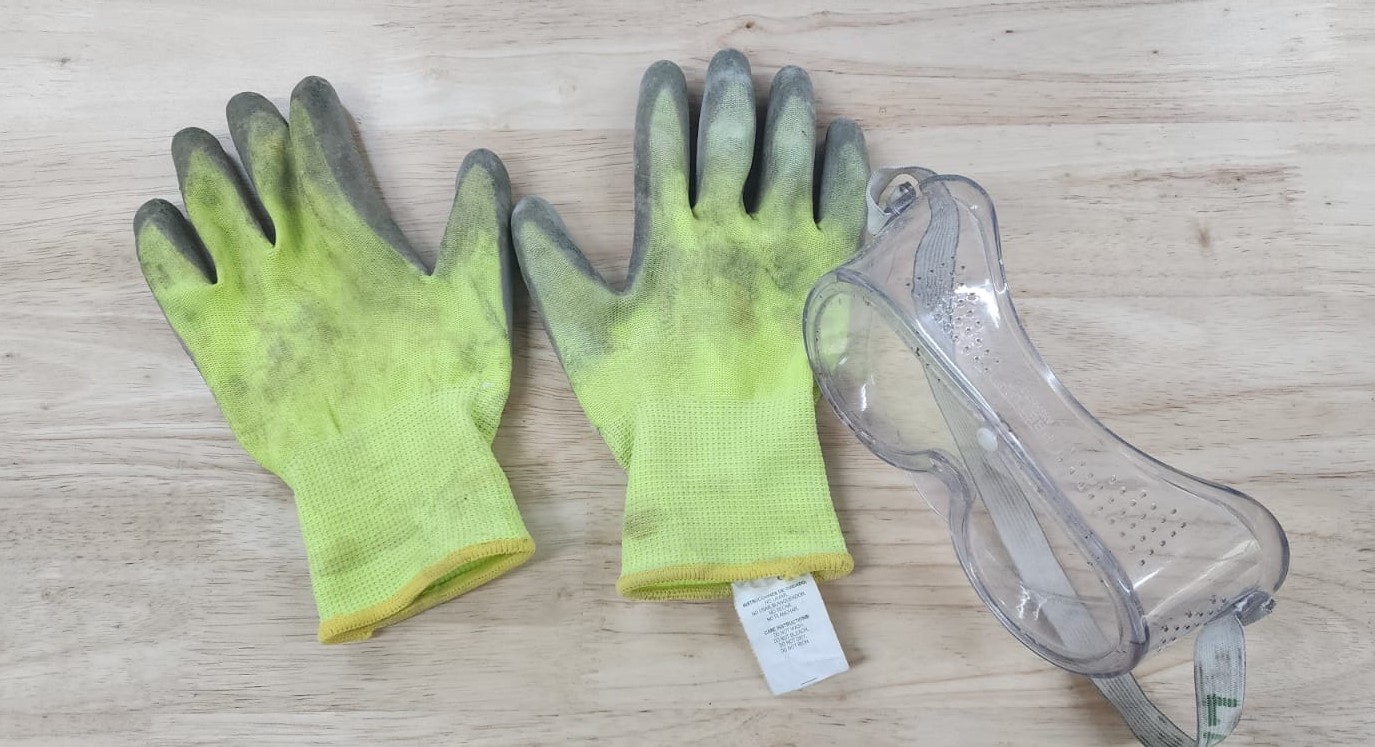
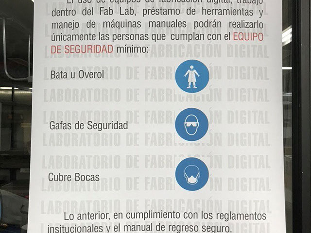
- Wear Overol and face mask as basic equipment.
- When the machine is on, we should keep a safe distance.
When you see or hear the bit hitting a screw:
- Stop the machine with the emergency stop button at the front of the machine or in the controller.
- Stop the vacuum.
- Go to the dust collector bag, loosen the round metal clip with which the plastic bag is attached to the machine.
- Inspect the bag.
If a little smoke is coming out:
- Close the bag to reduce the flow of oxygen.
- Walk out of the building and inspect again.
If a lot of smoke is coming out / a fire has started:
- Close the bag to reduce the flow of oxygen and see if that stops it enough to then walk out of the building.
- If it’s really bad, throw it out of (do call down to warn people).
- Take the fire extinguisher and run outside to put out the fire.
- Comment with guards and civil protection people of the University
CNC Settings
Machine Characteristics:
AXYZ CNC ROUTER · Work area. 1220x2440mm · Power: 220V, 5Hp · Mark. AXYZ · Model: 4008
The CNC settings used for 18mm MDF were the same for 18mm Plywood. Regular settings:
- Tool ¼” straight 1 flute
- Passes: 5 . 3.8mm per pass and 3mm for the last pass
- RPM: 11000rpm
- Speed: 58mm/seg
Leveling
We had to get the start point in X and Y coordinates And then the Z or height point with the different commands in G Code with the following codes from the manual controller:
- F10 for X and Y origin
- F24 bed height
- F20 material height
- F23 for adjusting material height
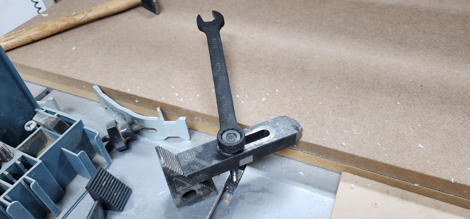
Fix material
We used CNC fixations from two vendors, Asia Robótica and AXYZ We used a spanish wrench for this purpose.
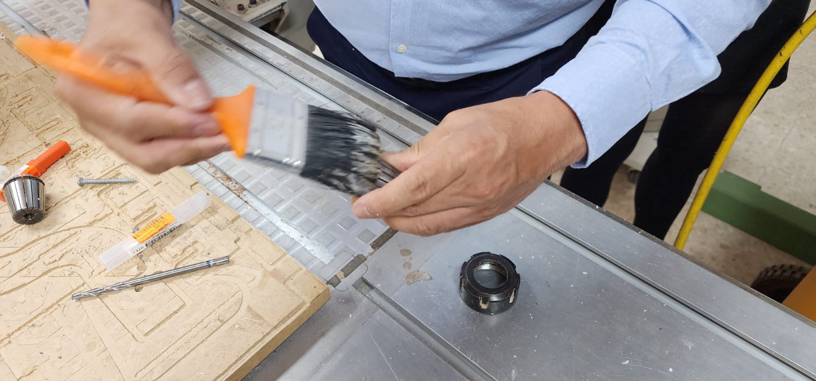
Bit loading method
Release neumatic lock for bit holder
Unscrew bit holder with press
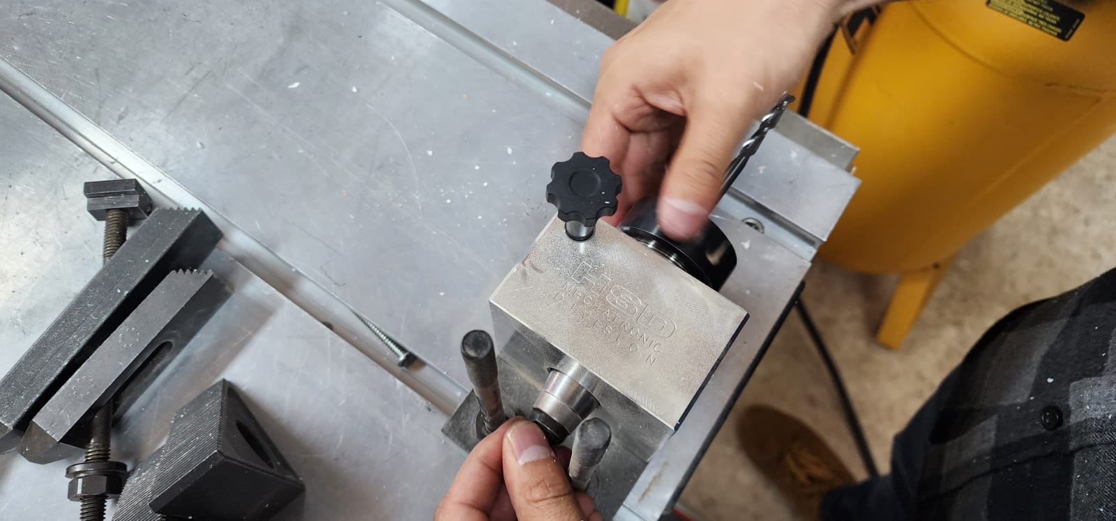
Clean holder, insert bit and put back in place
CNC Job specific Settings and Process
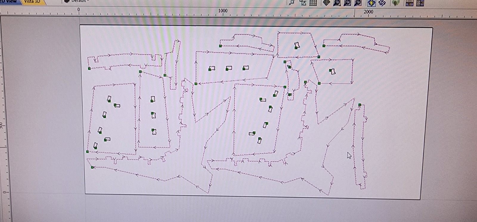
After the final placement of the different parts and taking in account a minimum clearance of 2.4 cm (four times 6.35mm for a 1/4”, that later became 5/16”) done with Open Nest. I took the file to the postprocessor used.
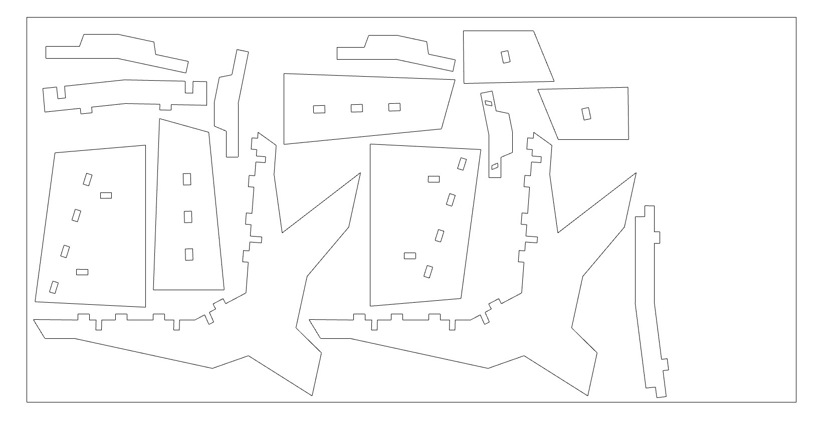
In our case we used V Carve Pro in order to set the feed and plunge rates, the rpm (12k) and the number of passes which for 19mm (1mm further from the width of the board) it was safe to go for 5 (19 / 5 = 3.8mm each, less than the bit width)
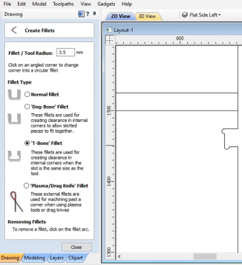
The perimeter was done with a preset for outcut, and the inner holes with a preset for incut. Wherever we needed a 90º angle I had to place dogbones. I thought it was easy to set the dogbones, but not really, we had to set this kind of fillet manually for each curve corner desired so the press fit holes would work. This was done with the Transfom / Fillet / T Dogbone option. This is the method used:
We had some (prior) training for the use of the CNC Router
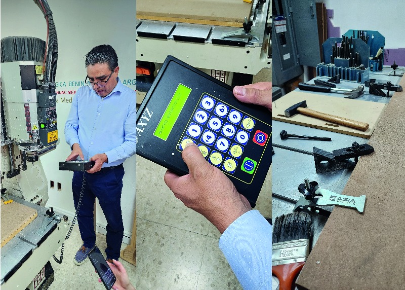
And after fixing the MDF board in the corners adjusting xy origin, and z height, we ran the cutting
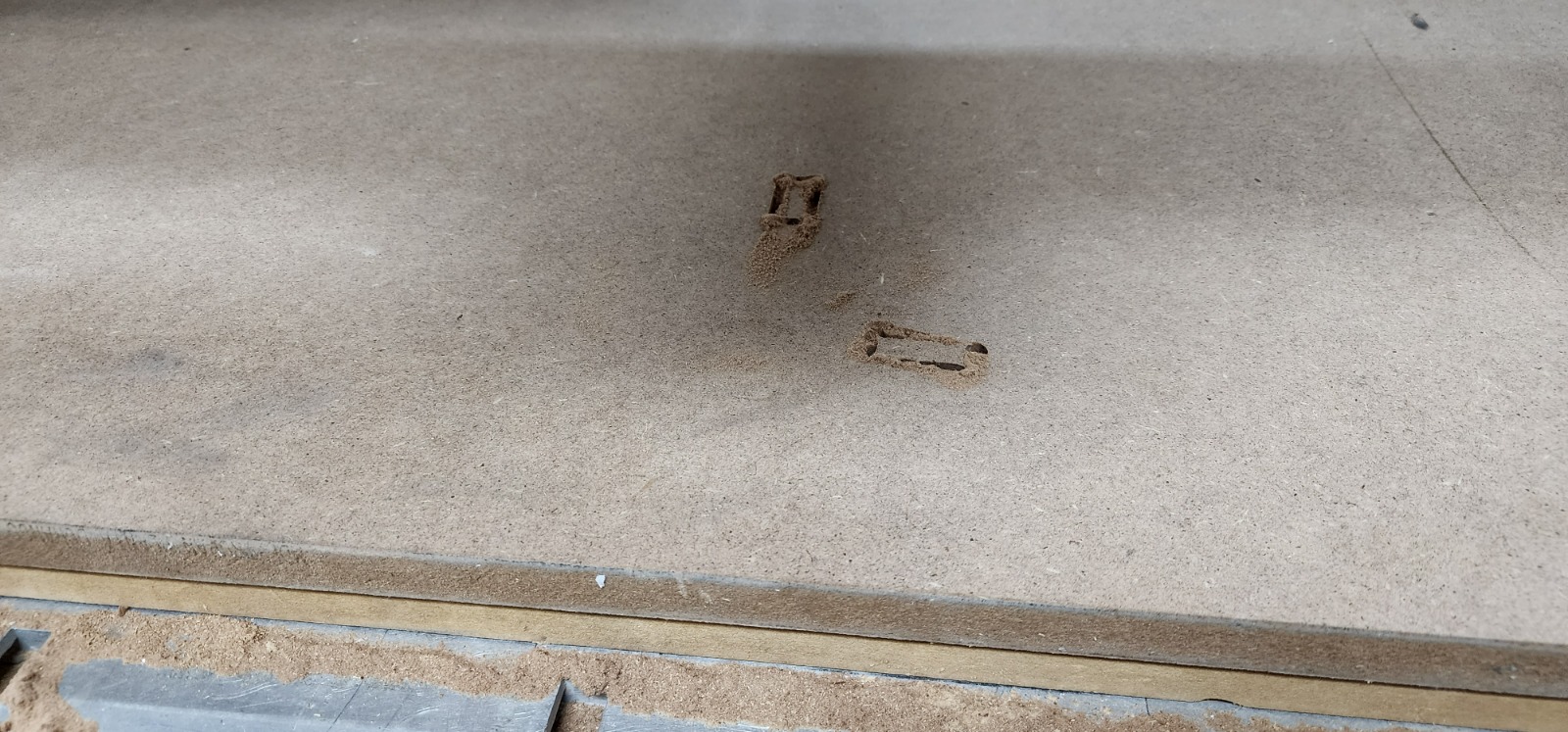
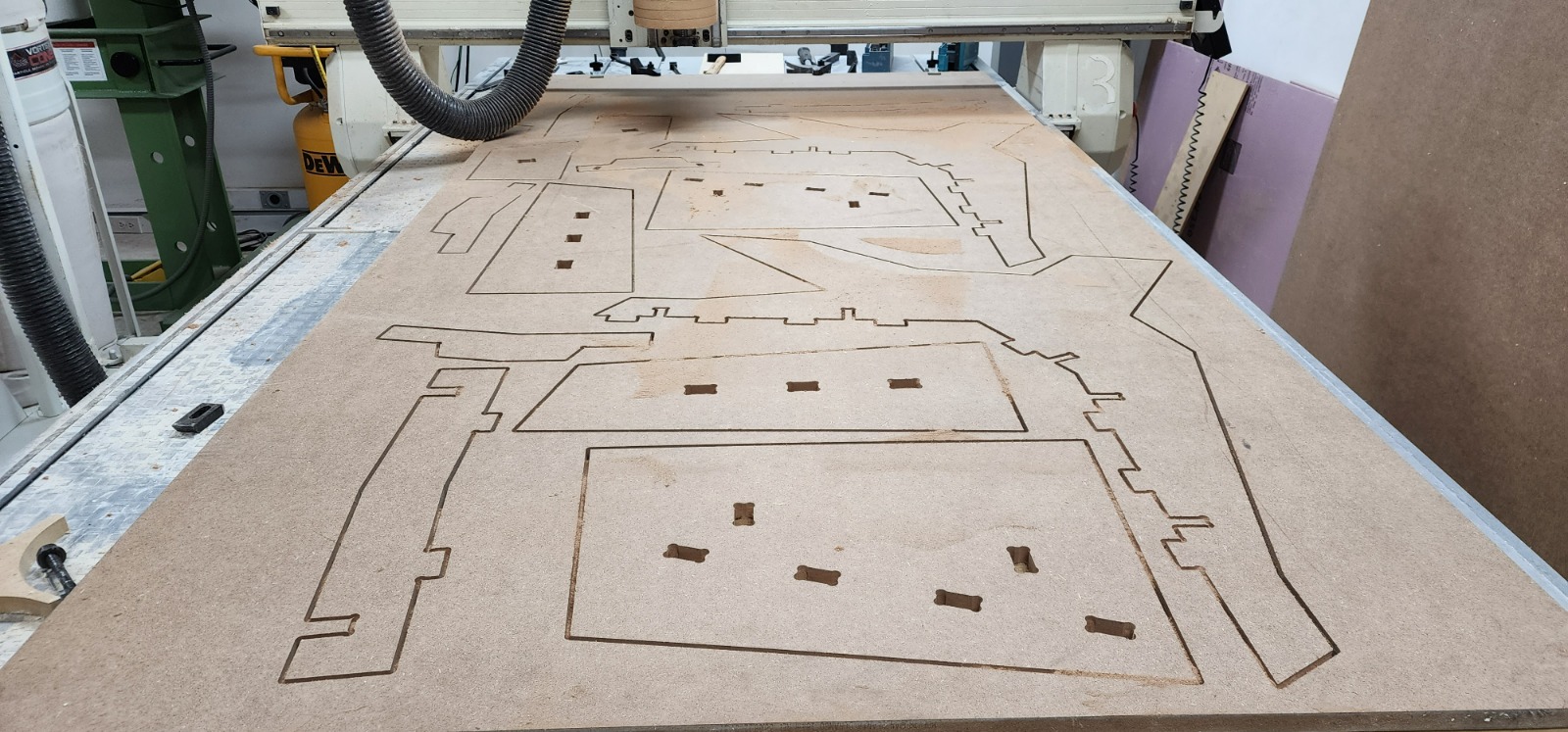
First we sent the inner holes, and checked how the dogbones came out, and they were Ok!
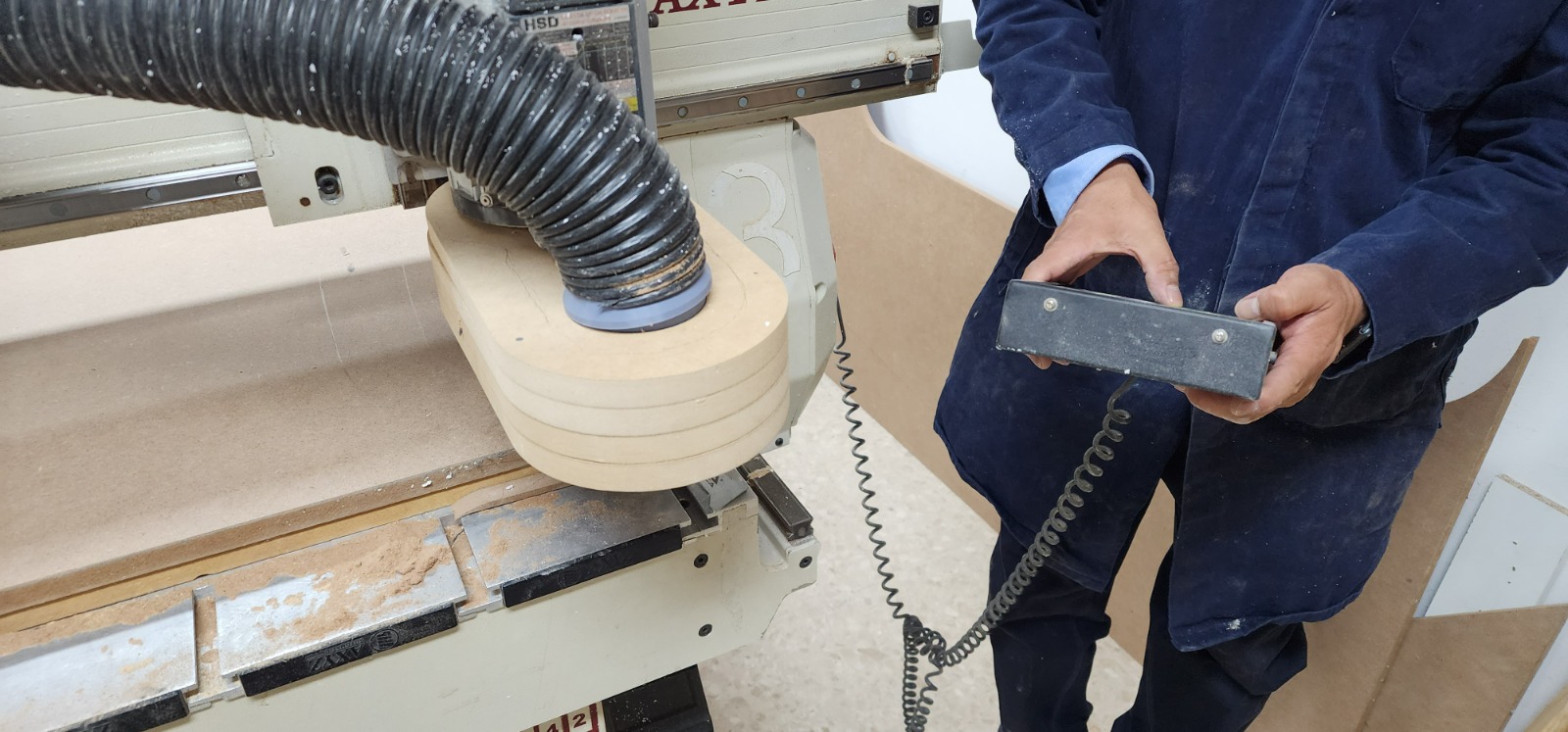
Then the rest, it took about 40 minutes
Debugging and fixing
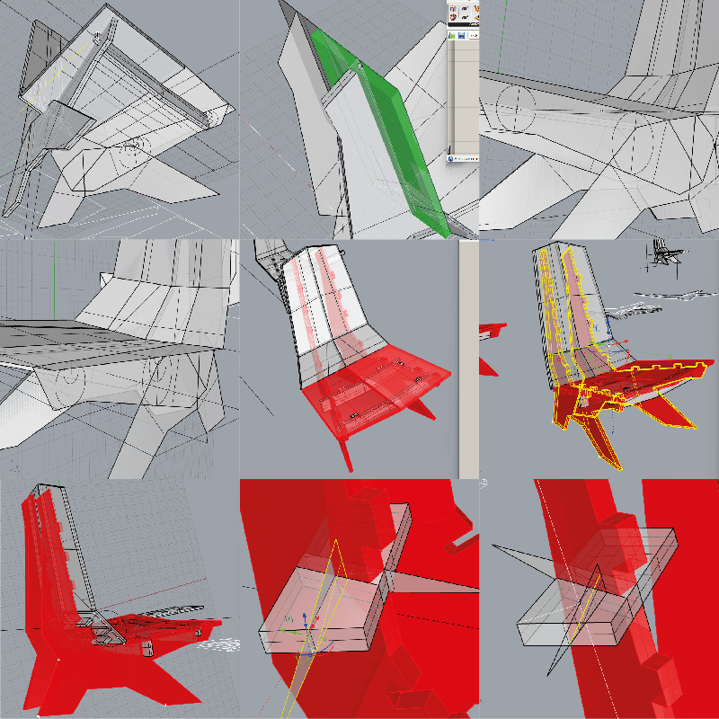
When I first tried to assemble the chair, I realized there were some problems to be fixed
a. Some of the notches in the bigger pieces were not wide enough to fit an oblique piece, the splitting process with the triangular surfaces was not quite well debugged, others were not wide enough because in this particular case entry and outgoing were not taken in account together
b. A couple of inserts were a bit displaced
c. Seat boards were overlapping each 2mm so they wouldn’t fit
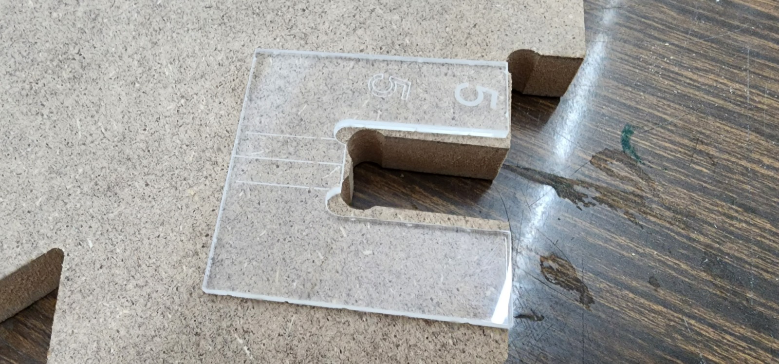
So, first the holes had to be reprocessed and double checked for how wide they should really be, and then with this re-check geometry, some templates were cut in laser for best guiding the hand routing of the piece. So the narrow notches got wider.
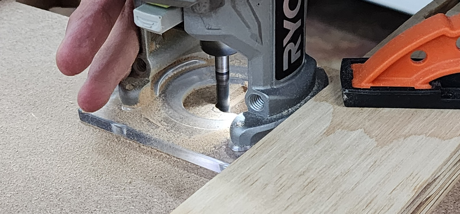
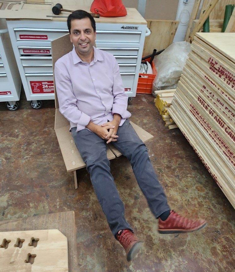
The inserts displaced were slightly sliced, and the boards for the seat were sawed as well. So finally I could assemble the chair (with some aid) and Voilà a functioning-confortable-1-week-chair-design-to-production!
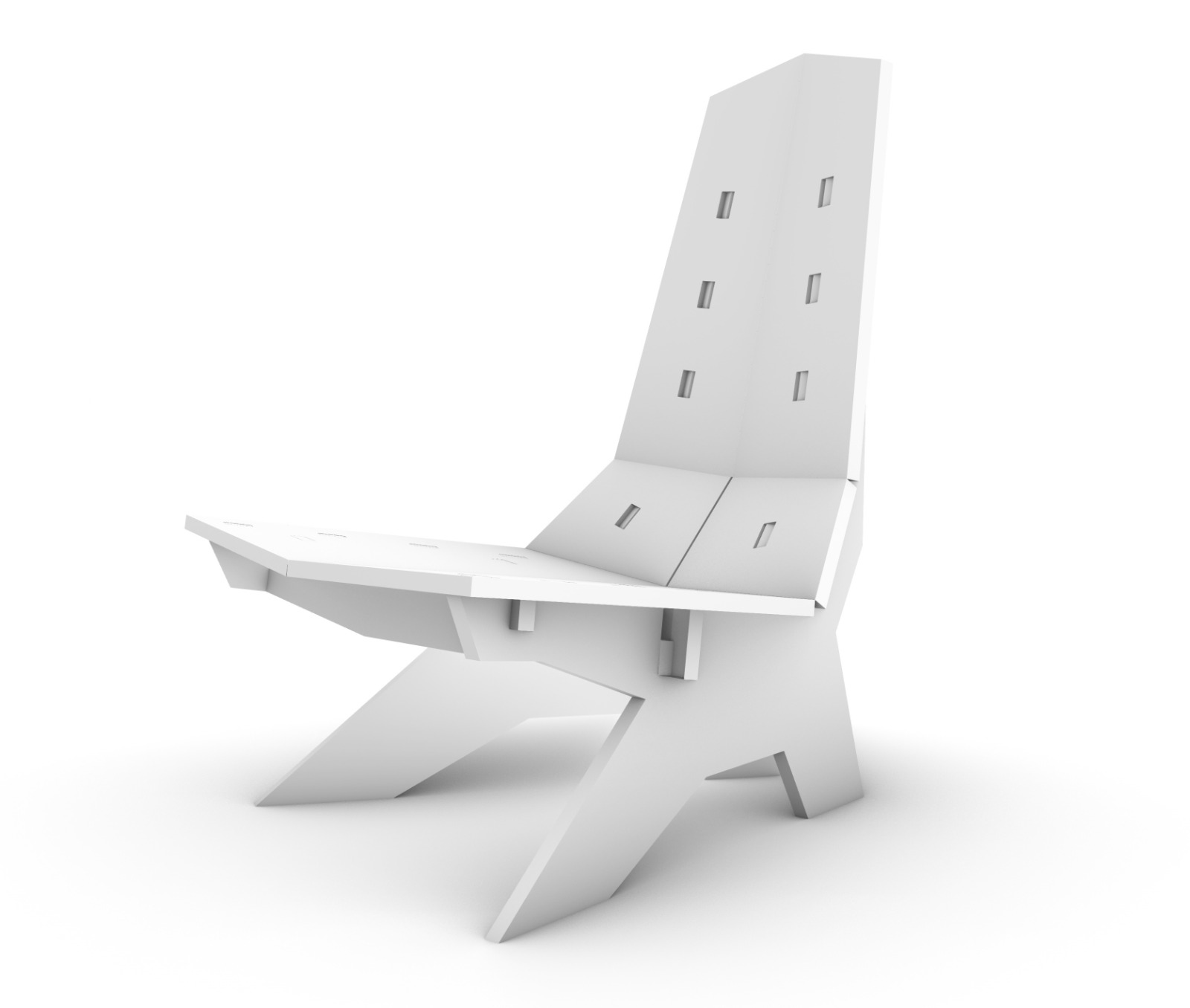
Final Product
And of course I had to test it in other ways such as placing my full weight and …
…fitting it into my car.
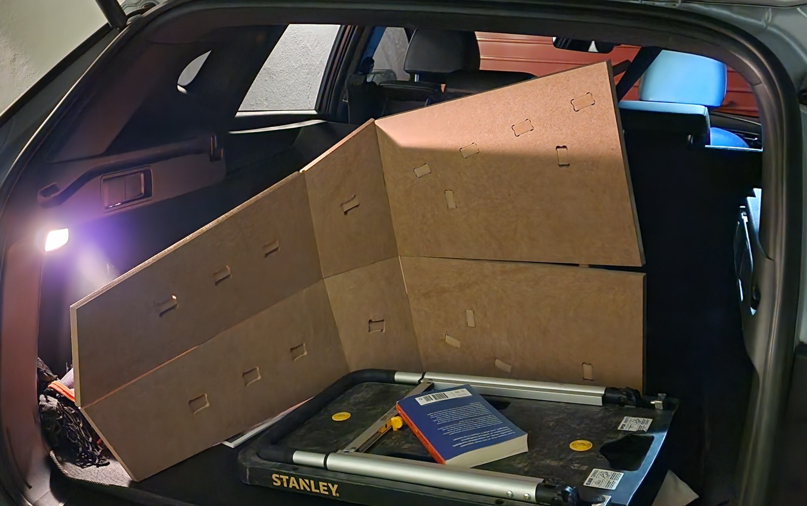
Mission accomplished!
This is the original file I used for post-processing with V-Carve Pro
I want to thank Nicole, Brandon, Diego and Diana (LATE trainees) for helping me out in different tasks for fixing the chair and Lalo for helping and training with the CNC in Fablab CDMX.