6. 3D Scanning and printing
Week 06 · 2023.02.22-2023.03.01
This week I worked 3d printing a ‘torture test’ to check if the 3d printer used was calibrated, designing (actually iterating) a different end effector articulated paddles for the gripper we have in Fablab CDMX and our own LATE (we have the same gripper)
I also scanned with different methods the manual router to be used in the final project.
- [x] Linked to the group assignment page Fablab Ciudad de México Page
- [x] Explained what you learned from testing the 3D printers
- [x] Documented how you designed and 3D printed your object and explained why it could not be easily made subtractively
- [x] Documented how you scanned an object
- [x] Included your original design files for 3D printing
- [x] Included your hero shots
3D Scan
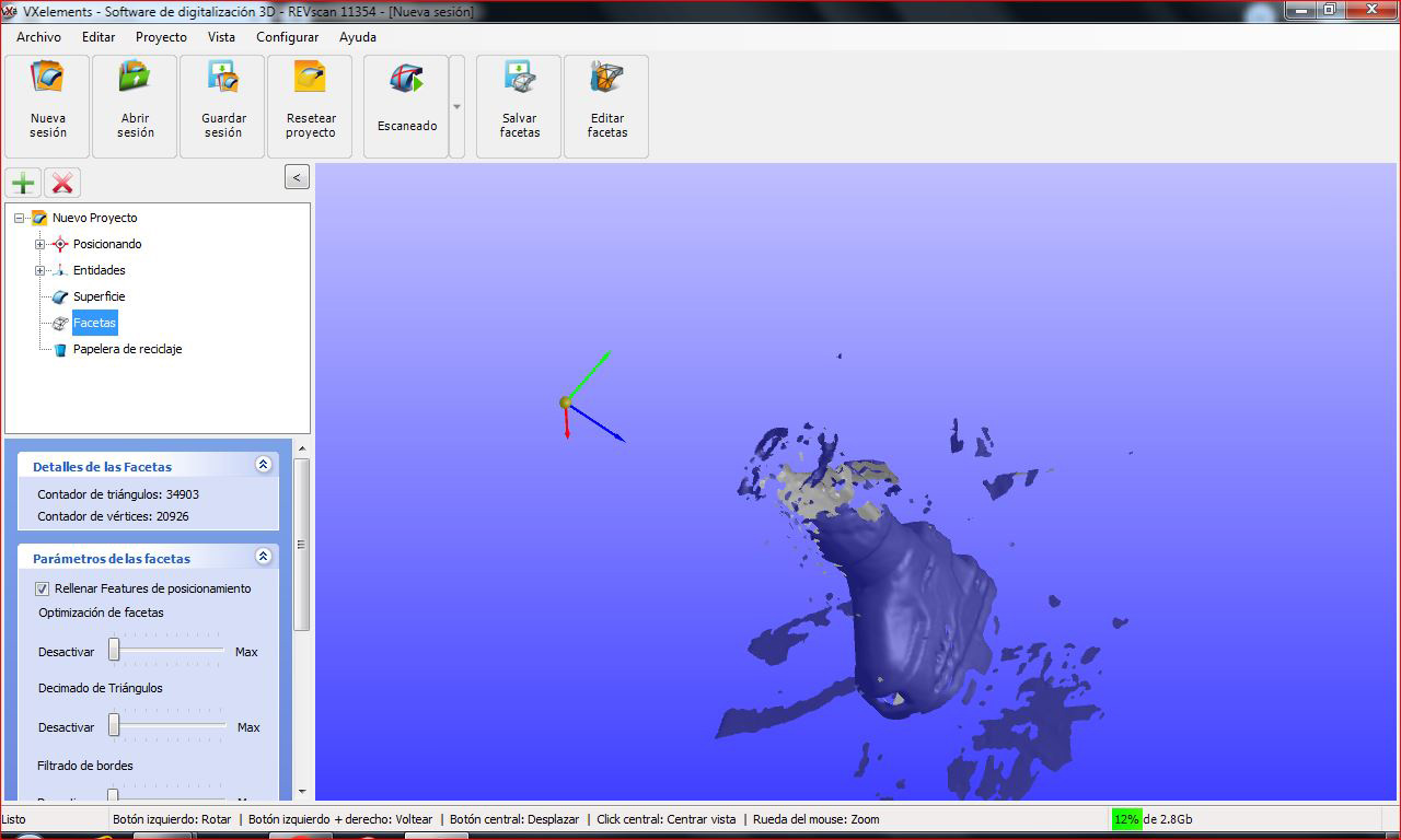
Creaform Handyscan
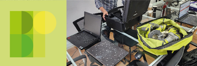
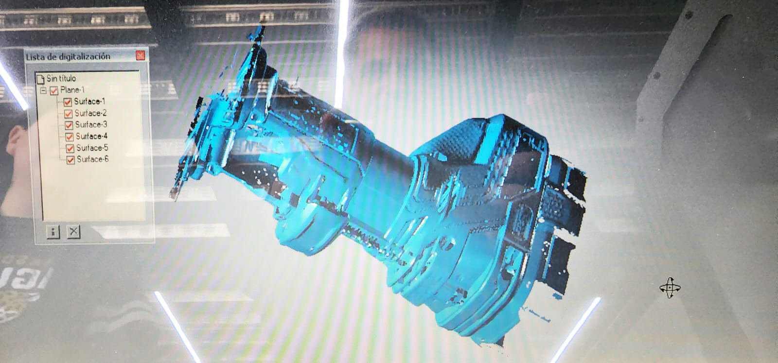
I used the Creaform Handyscan from 2013 in a Windows 7 computer for the first effort of scanning the handheld tool battery and router, investing around 30 minute in obtaining the following:
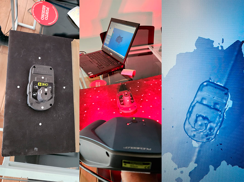
I then went for a bigger objective working on scanning a handheld router with a bigger battery.
I then went for a bigger objective working on scanning a handheld router with a bigger battery.
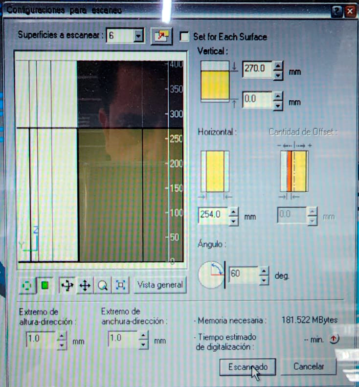
Roland Picza Scanner
I tried with the regular configuration on the (old) Roland Picza Scanner on a Windows XP computer, and scanned the battery pack first with the following results:

After observing the (poor) output for this first scan, I tried putting toghether the best possible configuration for this scanner and scanned the full handheld router with the big battery pack, which took more than two hours, thankfully enough the Picza Scanner is automatized, so there is no hoovering around with a weight in the hand as with a handheld scanner.
The output came surprisingly better than what I would’ve thought.
Taking screen captions in an XP is not as easy as nowadays that’s why I preferred to take photographs.
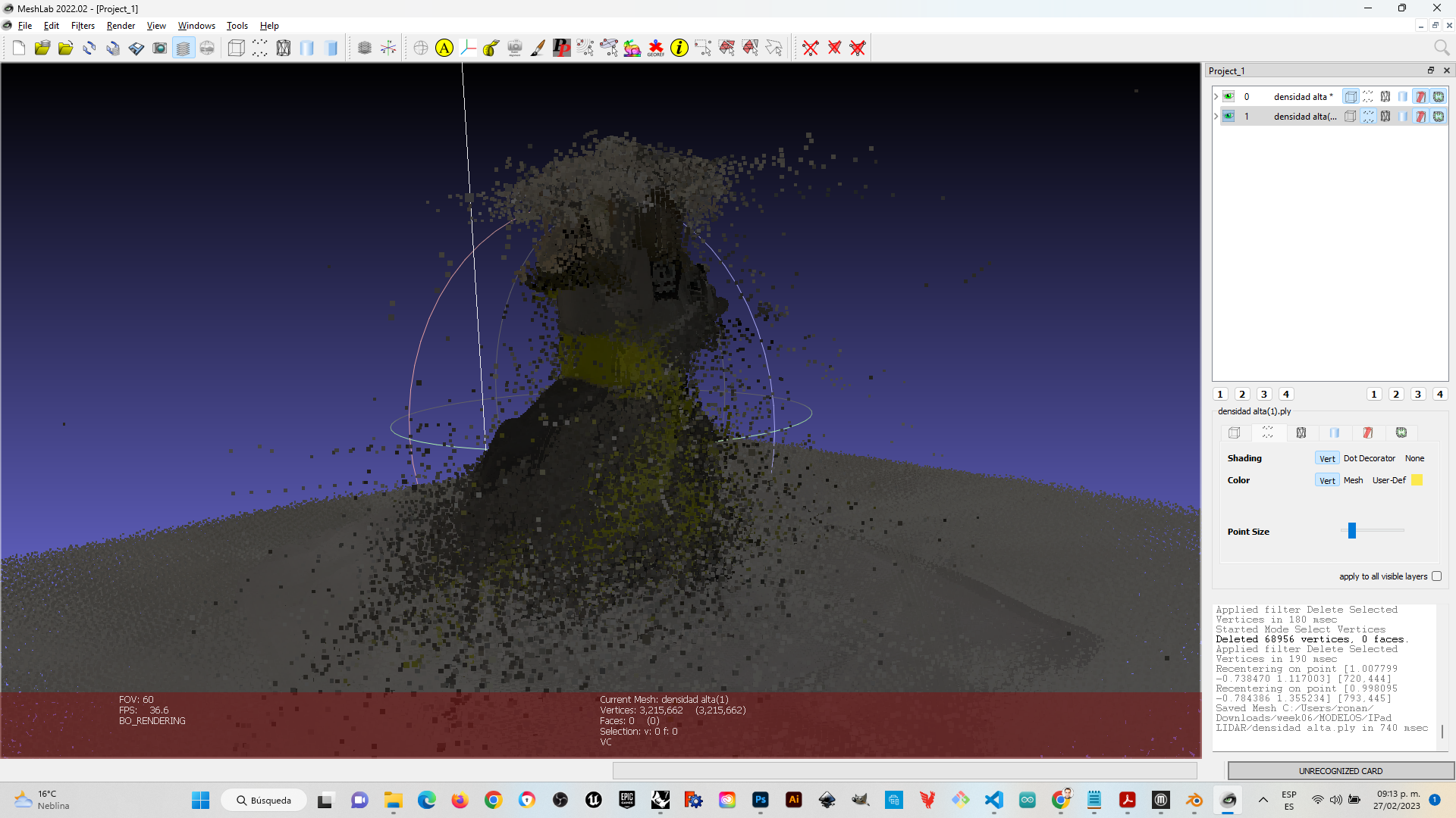
Apple Lidar Sensor
I then tried (with the aid of Jorge Bobadilla a LATE student) to scan with a Lidar senor from a Professional Ipad and obtained the worst of all results
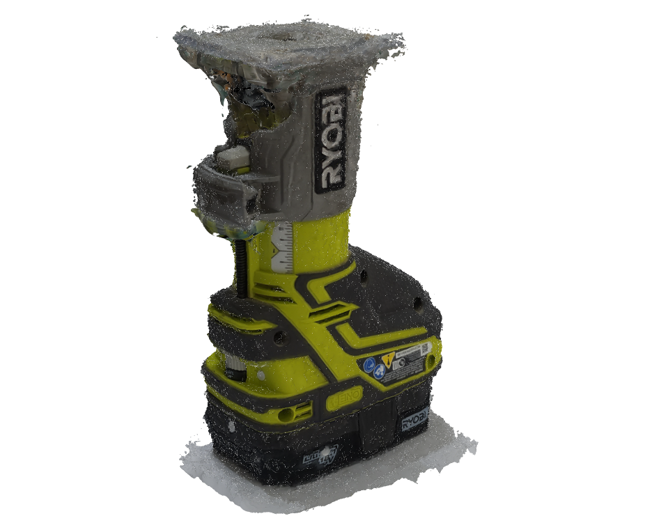
Photogrametry with Samsung Galaxy S22 Ultra photos
As a last attempt I tried (again with the aid of Jorge Bobadilla) to build up a model from photogrametry, with photos from a Samsung Galaxy S22 Ultra, assembled in Meshlab. And I obtaind the most complete of all scans:
3D Print embedded mechanism
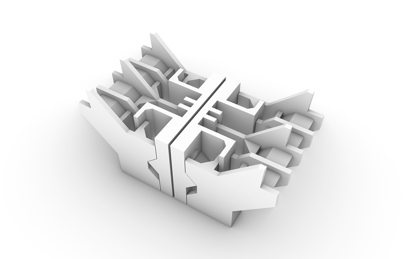
I iterated from previous gripper paddles I designed and evolved a type of paddles needed for the kind of work I’m willing to perform with my final project by modelling in Rhino. The objective of this paddles is to grip from inside different size and shapes of plywood. This paddles get screwed to a couple of metal plates placed in the pneumatic gripper of our robotic arm. The mechanism is 3d printed and works right after it is printed, no post-assembly needed. The intern protruding geometries of the paddles make it really hard if we opted for substractive manufacture.
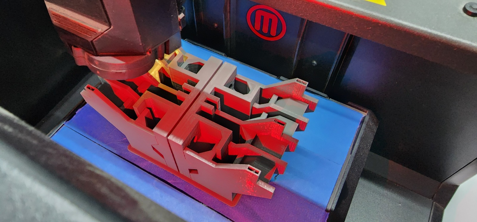
Printing process in Makerbot 5G. I had to change the spool since I checked the amount on demand and I weighted what was left, and it was not enough, the print took around 20h (even though it announced it would take 25h, 3d printers don’t always calculate the right time). I couldn’t use the Z18 printer since the extruder is clogged.
This is how it finished printing and after removing the raft
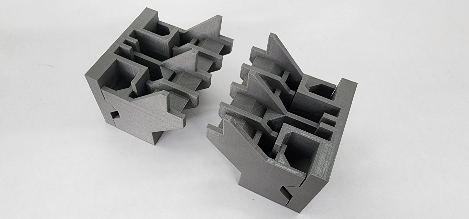
We mounted it in the robotic arm, and made a manual grip, It worked just fine!
The wood piece weighted 1.1 kg and presented no problems in manipulating.
Embedded mechanism in paddles for gripper
I would like to thank additionally Nicole, Lorna and Brandon (our new trainee) for helping with the footage and changing the end efector in the robotic arm.
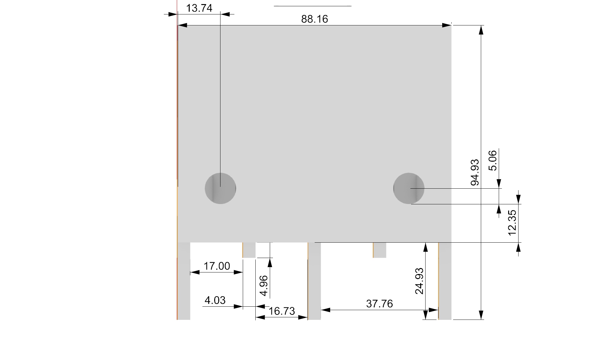
Gripper paddles design insight
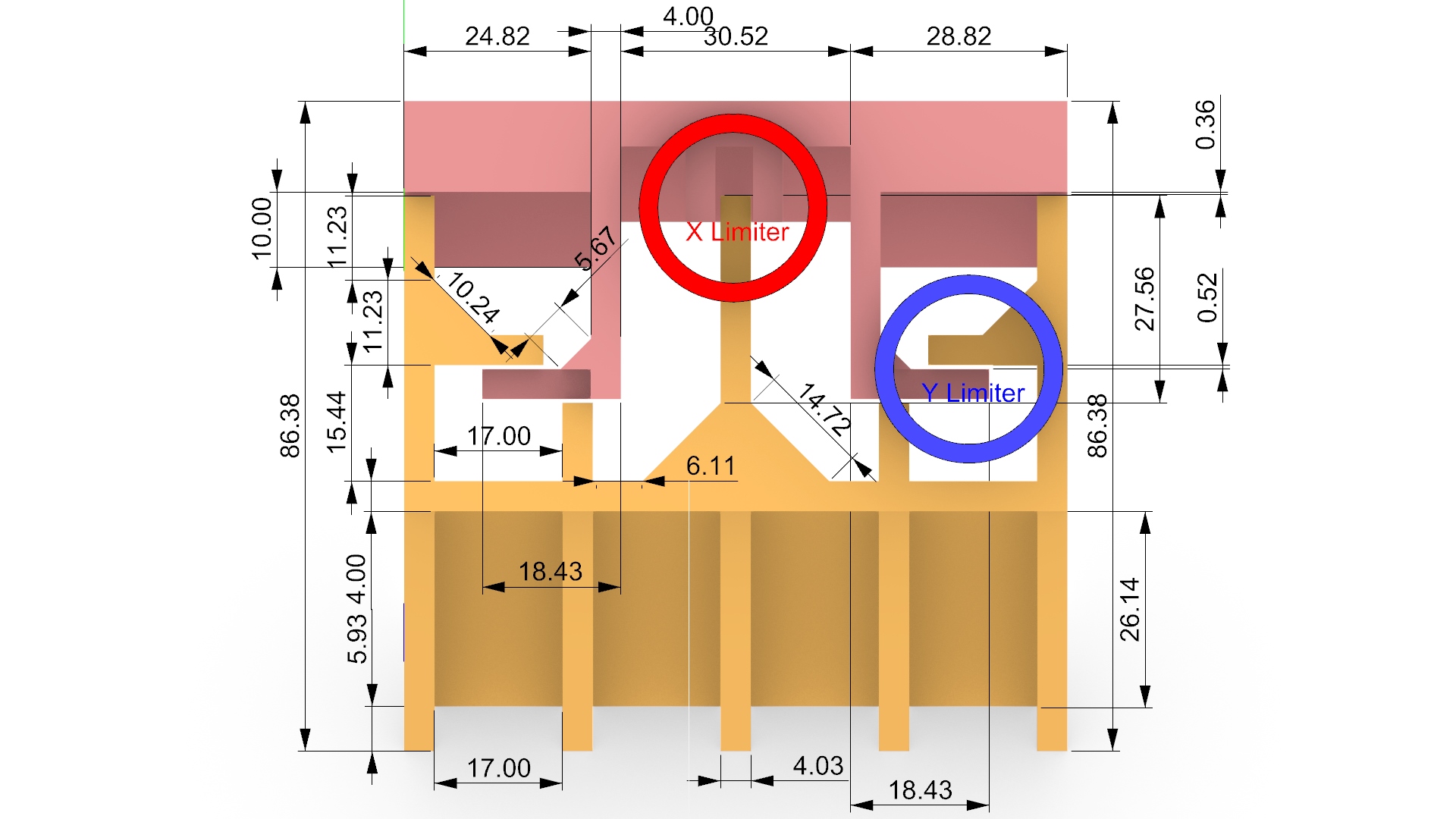
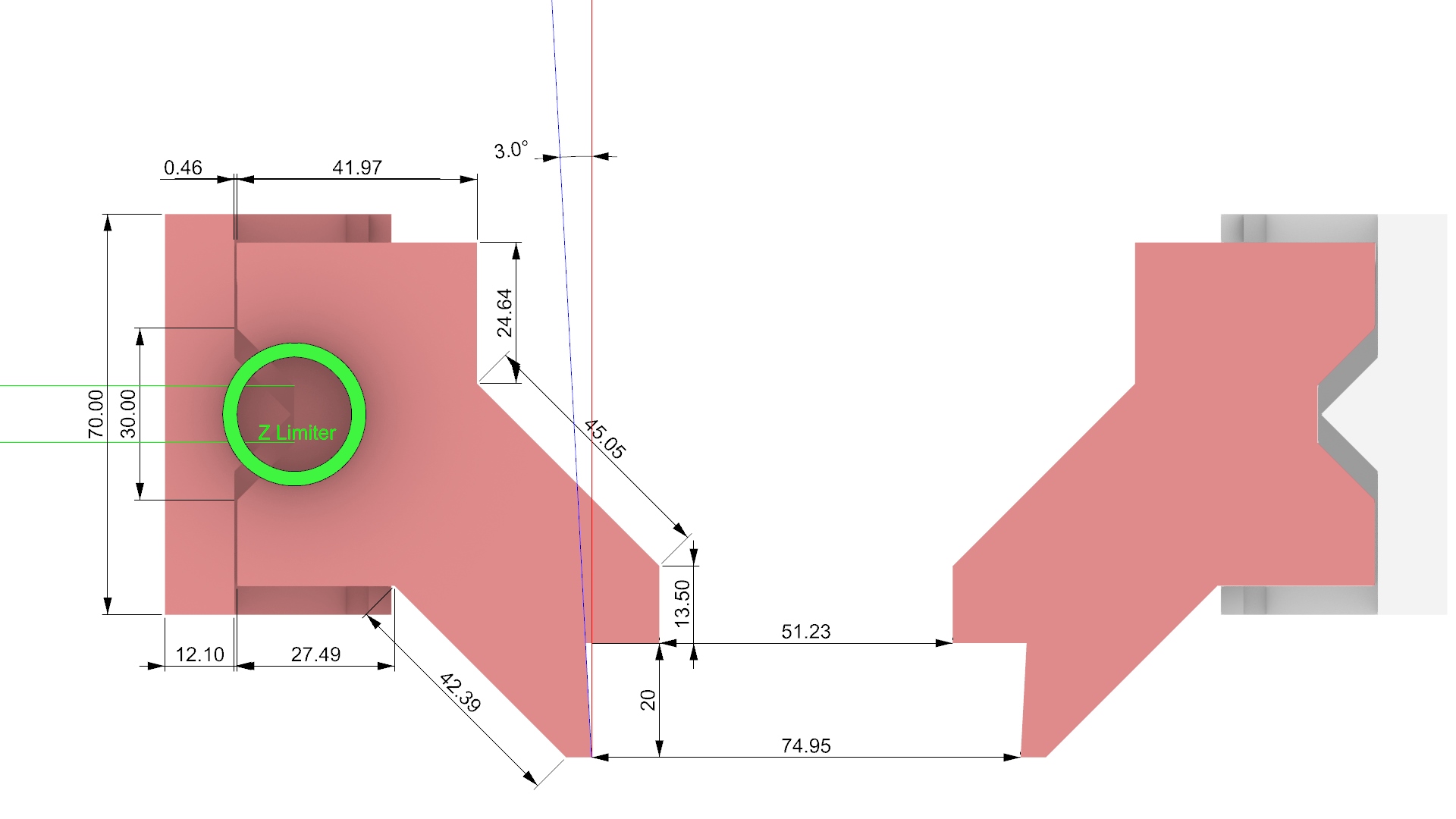
The paddles were designed having in mind the capacity for sliding in the Z direction at least one centimeter. So the geometry of each paddle was developed in to pieces, one fix to the metal paddle and the other capable of sliding. I configured some walls (protruding geometry) that would limit movement in X, Y and Z directions. For the first two there is a tolerance of around .5 mm in order to mantain them as two separate geometries, in the case of Z there is a gap of 10mm and a triangle that helps to indicate how much is sliding from the lateral view
3D Printing Settings and torture test
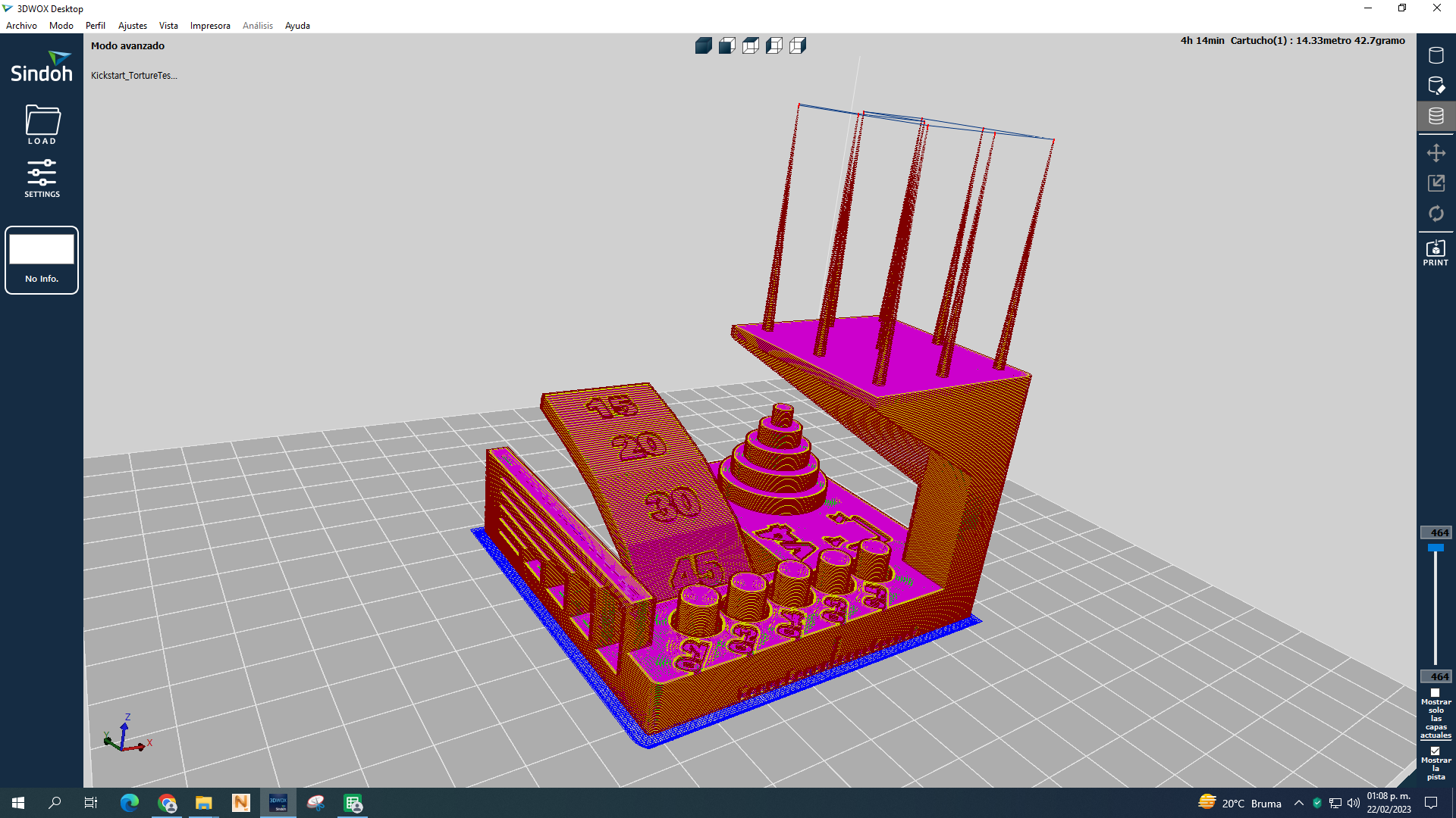
I downloaded from thingiverse, following this link the following test of callibration. Ultimate torture test for printing in a Sindoh 200 in fablab Ciudad de México.
Aftwerwards I downloaded a different test from here All In One 3D Printer test for testing the Makerbot 5G in our lab LATE, again with a regular configuration and came up with better results. Regular settings, just changed 30% infill (since its a working piece, this percent I consider the minimum in this sense), added support, raft and 40ºC for the heated chamber if I used the Z18.
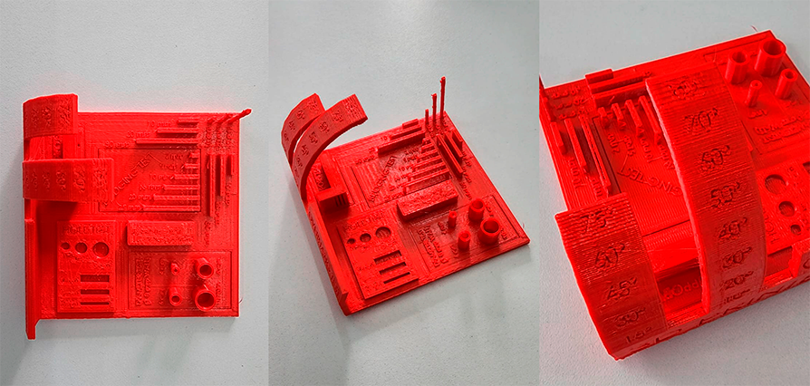
Except for some warping in the base the print went out quite well
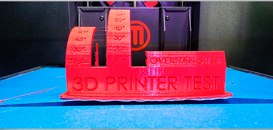
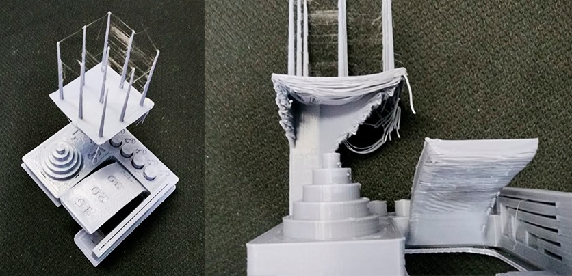
Torture test with Sindoh printer
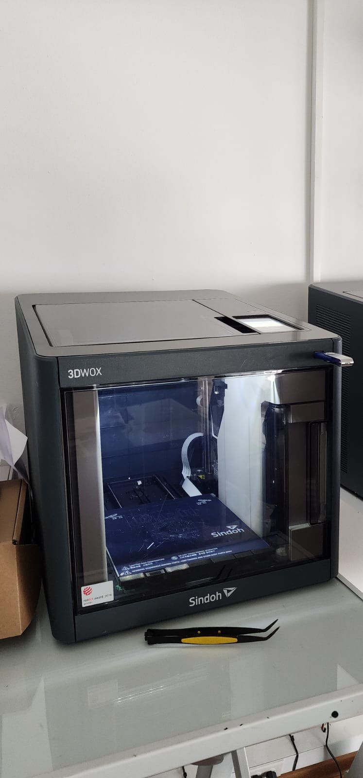
For this test we used a Sindoh 3DWOX regular printer. At first the filament got jammed, so we had to start over again. We went with the regular configuration.
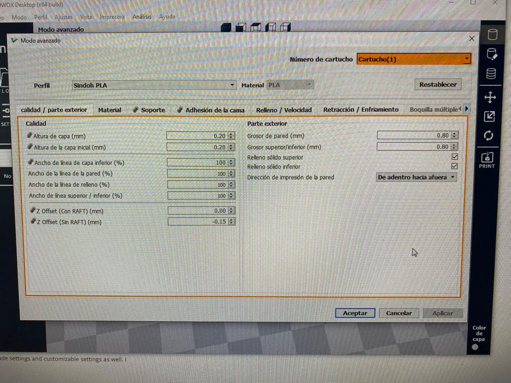
Exterior
- Height of layer 0.20 mm
- First layer height 0.20 mm
- Width of line of previous layer 100%
- Width of line on wall 100%
- Width of infill line 100%
-
Width of superior/inferior line 100%
-
Z offset with raft 0.00
- Z offset without raft -0.15
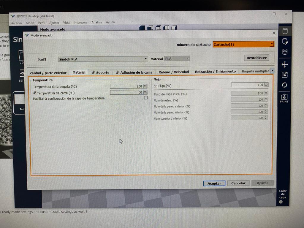
Material
- Nozzle temperature 200ºC
- Bed temperature 60ºC
- Flux 100%
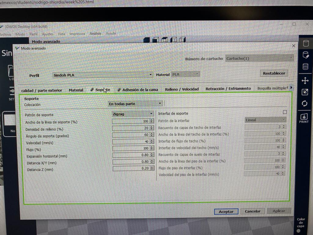
Support
- Zigzag pattern
- Width of support line 100%
- Infill density 20%
- Support angle 60º
- Speed 40 mm/s
- Flux 100%
- Horizontal expansion 0.80 mm
- X/Y Distance 0.80 mm
- Z Distance 0.20 mm
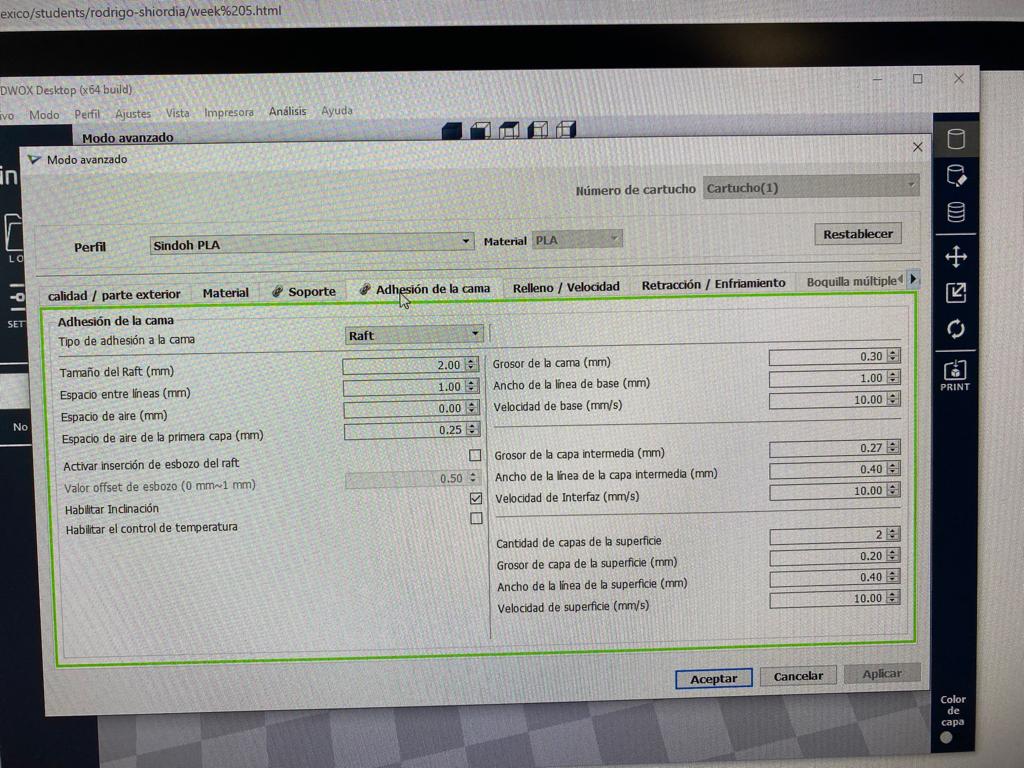
Bed adhesion
- Type of adhesion to bed Raft
- Raft size 2.00 mm
- Space between lines 1.00 mm
- Air space 0.00 mm
- Air space from first layer 0.25 mm
- Activate insertion of draft from raft None
- Offset value of draft 0.50 mm
- Enable tilt Checkmark
-
Enable control temperature None
-
Bed width thickness 0.30 mm
- Base line width 1.00 mm
- Speed base 10.00 mm/s
- Middle layer thickness 0.40 mm
- Middle layer width line 10.00 mm
- Interface speed 10.00 mm/s
- Layer amount of surface 2
- Thickness of layer from surface 0.20 mm
- Line width from surface 0.40 mm
- Surface speed 10.00 mm/s
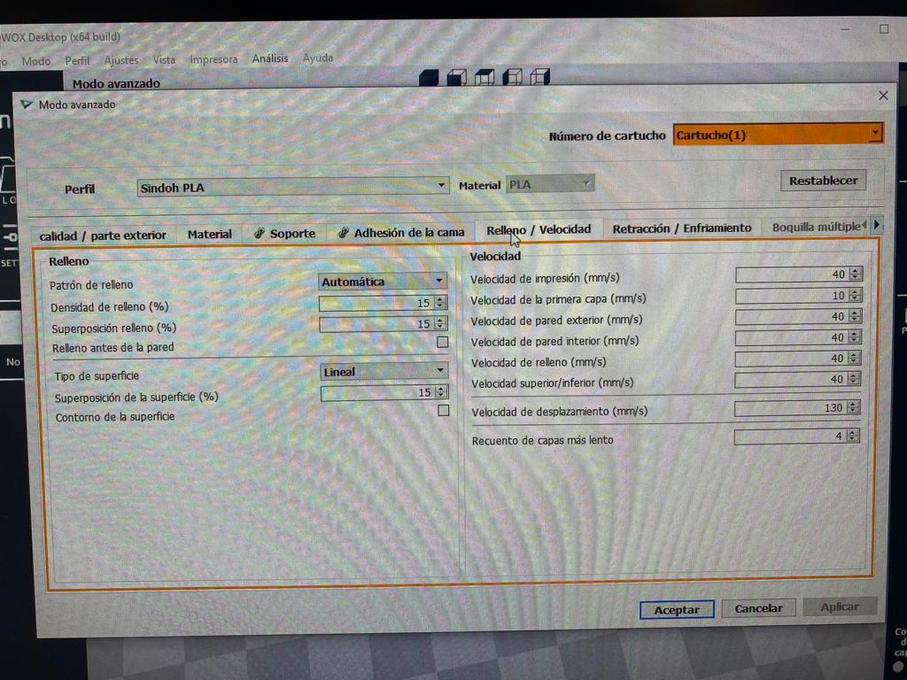
Infill / speed - Fill pattern Automatic - Fill depth 15% - Fill superposition 15% - Fill before wall None - Type of surface Linear - Surface superposition 15% - Stroke surface None
- Print speed 40 mm/s
- First layer speed 10 mm/s
- Outer wall speed 40 mm/s
- Inner wall speed 40 mm/s
- Fill speed 40 mm/s
- Higher/lower speed 40 mm/s
- Displacement speed 130 mm/s
- Lower counting of layer 4