14. Molding and Casting

Week 14 · 2023.04.19-2023.04.26
This week it was a week that started on how to find out how would a small piece of wax would be milled to host a small casted object that would be useful for the final project, such as a button. Then it further developed in a piece to add weight to my workbench but demanded a larger milling process.
- [x] Linked to the group assignment page and reflected on your individual page what you have learned
- [x] Reviewed the safety data sheets for each of your molding and casting materials, then made and compared test casts with each of them.
- [x] Documented how you designed your 3D mold and created your rough and finish toolpaths for machining, including machine settings
- [x] Shown how you made your mold and cast the parts
- [x] Described problems and how you fixed them
- [x] Included your design files and ‘hero shot’ of the mold and the final object
Research
So first I thought to mill a small piece of wax which was provided by Fablab CDMX, and I thought maybe it would be a good idea to finally do my own chess set, and why not start with the bishop, so I found the measures recomended for the Staunton chess set and developed a model for this piece.
After some rethinking I left aside this idea and concentrated into developing a piece that would add weight for my workbench, that would be modular and then the idea developed even further into looking for a flat side for pouring into the mold, but would be able to assemble with another piece identical, then the challenge arised.
Design
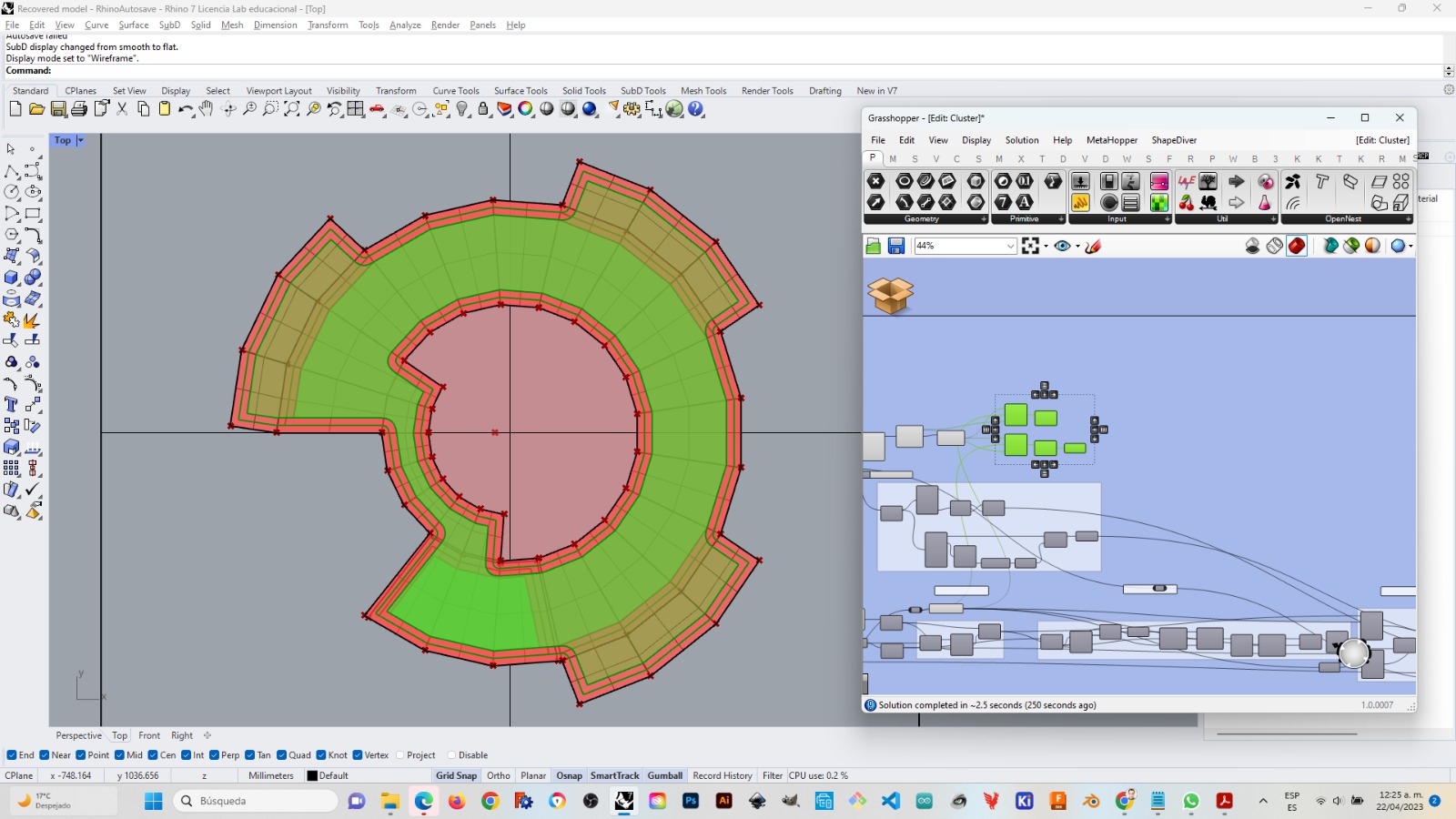
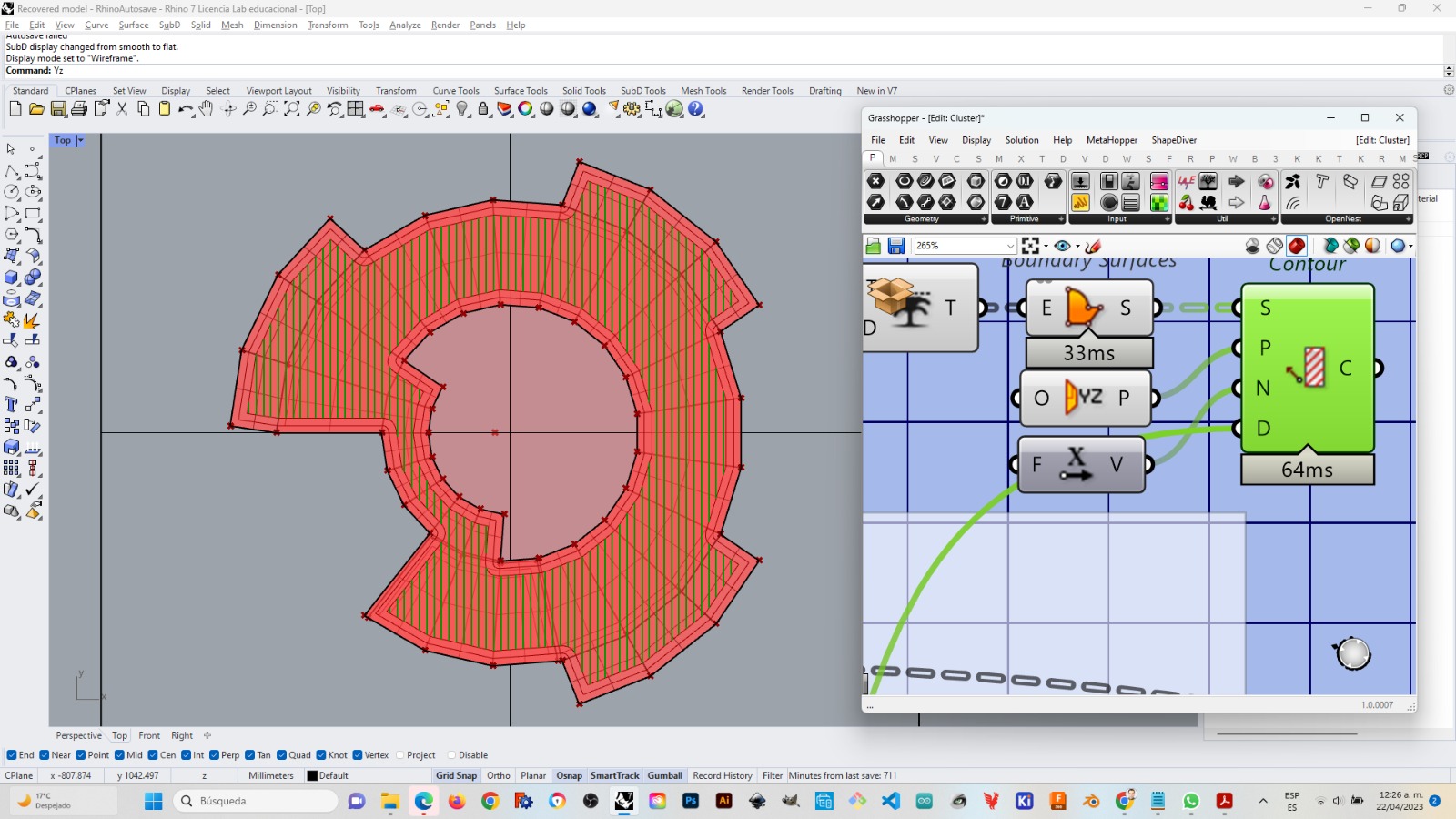
I designed the piece 100% parametrically in Grasshopper (just the way I like)
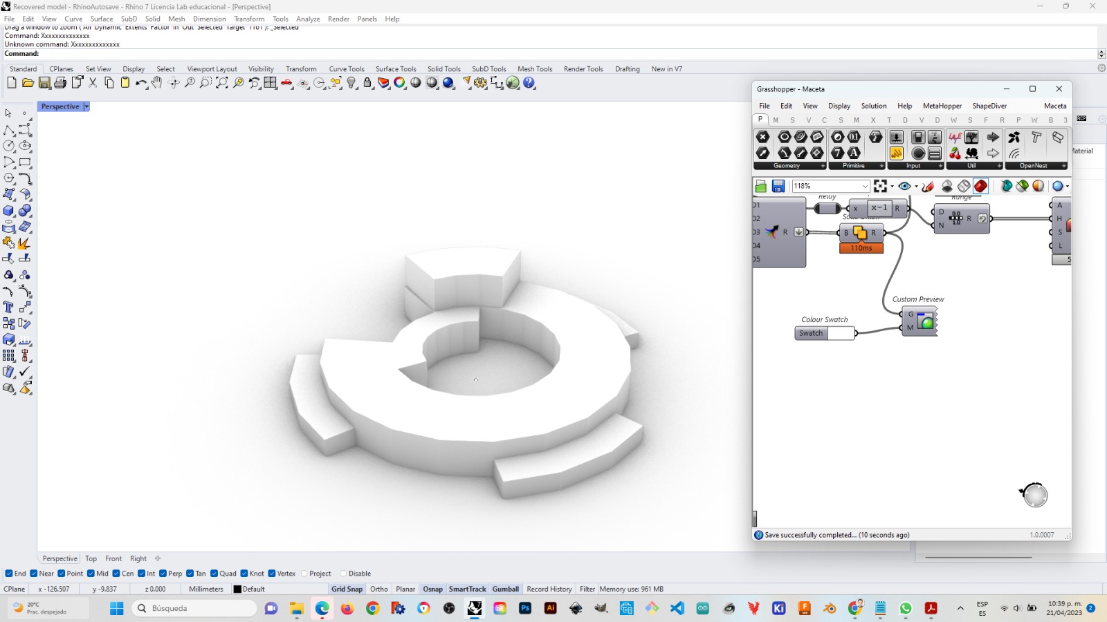
It was done with some circles, lofts and extrusions. The circle was divided in points and the number of points was manipulated in order to have these arching polyedra.
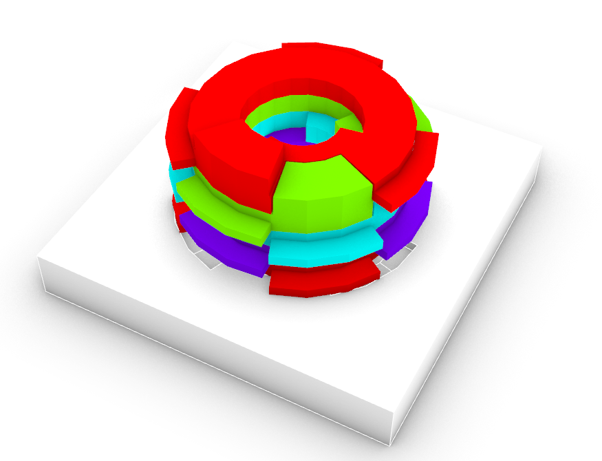
I did a test for piling several modules, and It was important to take in account a small gap as a tolerance between the nodge and the gap that assembled the piece not to force assembly. I thought it would be a good idea to build into the geometry some handles that would create a sloping diagonal while assembled in torsion, and would allow to pick up easier each portion. This module was also thought to become some kind of pot for plants been planted in the center, since the original idea for building weight into the workbench would be through a plant pot. Actually the center has the diameter of a 1kg yogurt container.
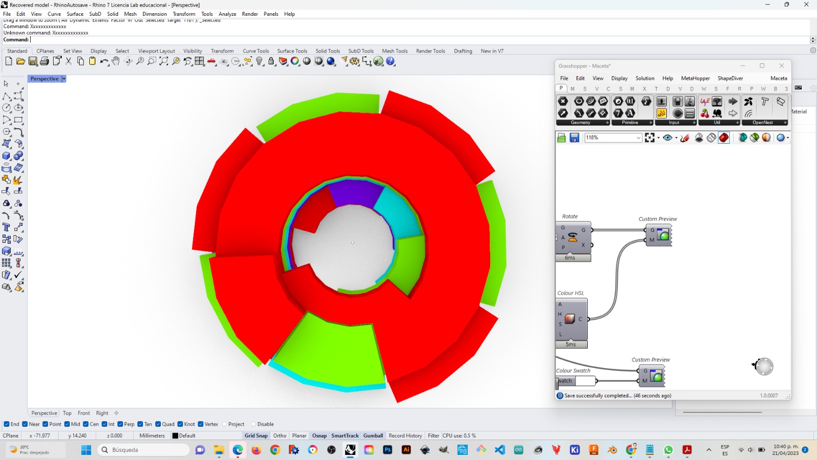
Then I built the mold by a difference boolean operation with a box
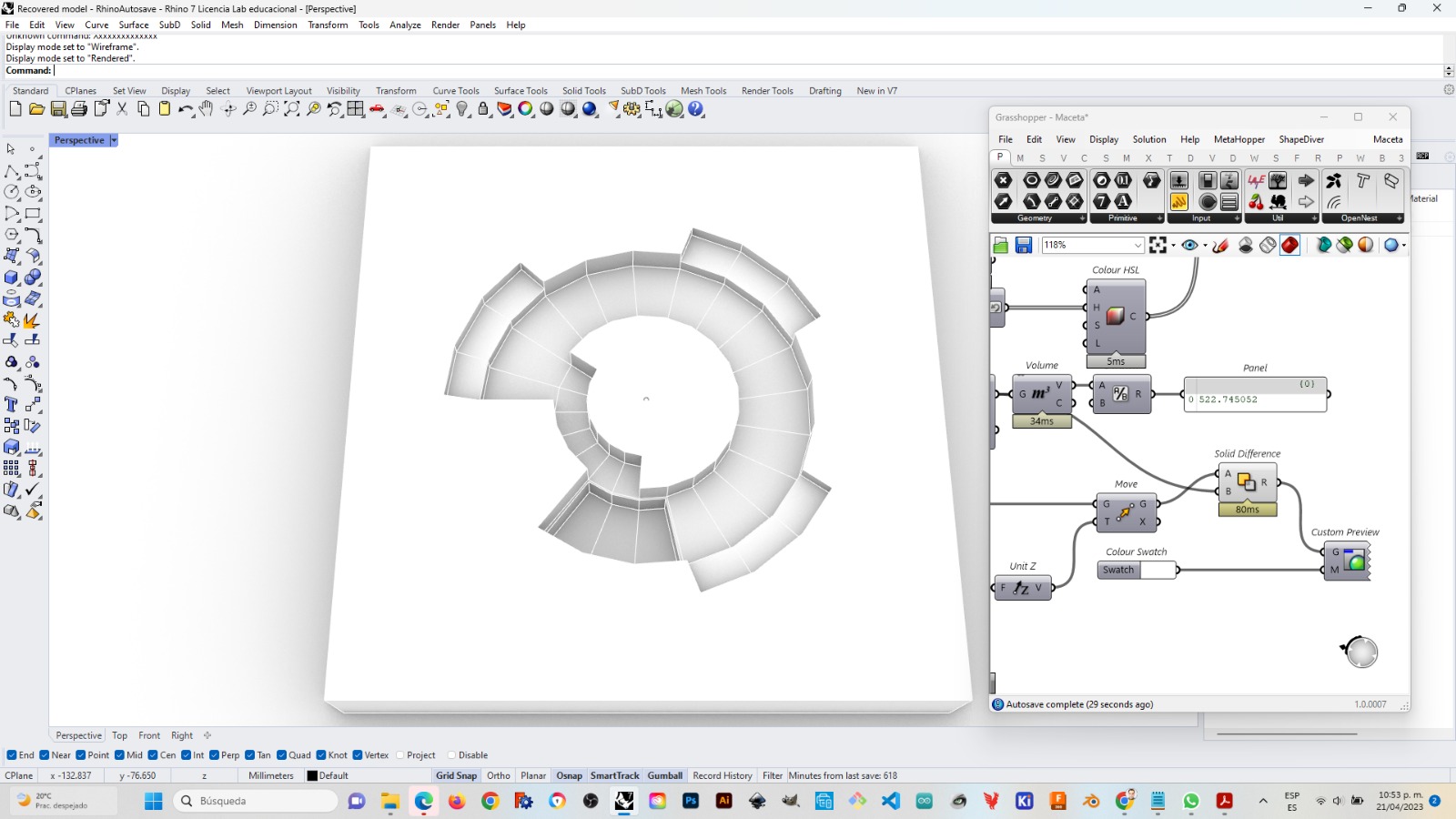
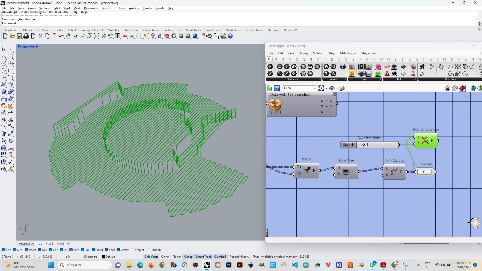
Based upon previous experiences I separated the main milling from the lateral surfaces in order to divide into two different processes, first the general milling that would finish the horizontal surfaces, while the lateral surfaces would be done with a final finish that would follow every curve instead of the milling zig zag.
I ideated how to developed the rutes for milling, and probably was what took me more time since I had to do quite some debugging.
Milling
Already with the programming for the rutes and the development of the rapidcode for our robotic arm. I had some pieces of foamular cut and glued among them and then also glued to a 12 mm plywood base, as we have done in LATE lab for previous milling processes. A ball-end bit 1/4” was used for milling (Amana Tool 46294-K CNC Spektra Extreme Tool Life Coated SC 2D and 3D Carving 0.10 Deg Straight Angle Ball Nose x 1/4 D x 1/8 R x 1-1/2 CH x 1/4 SHK x 3 Inch Long x 2 Flute Router Bit 46294-K)
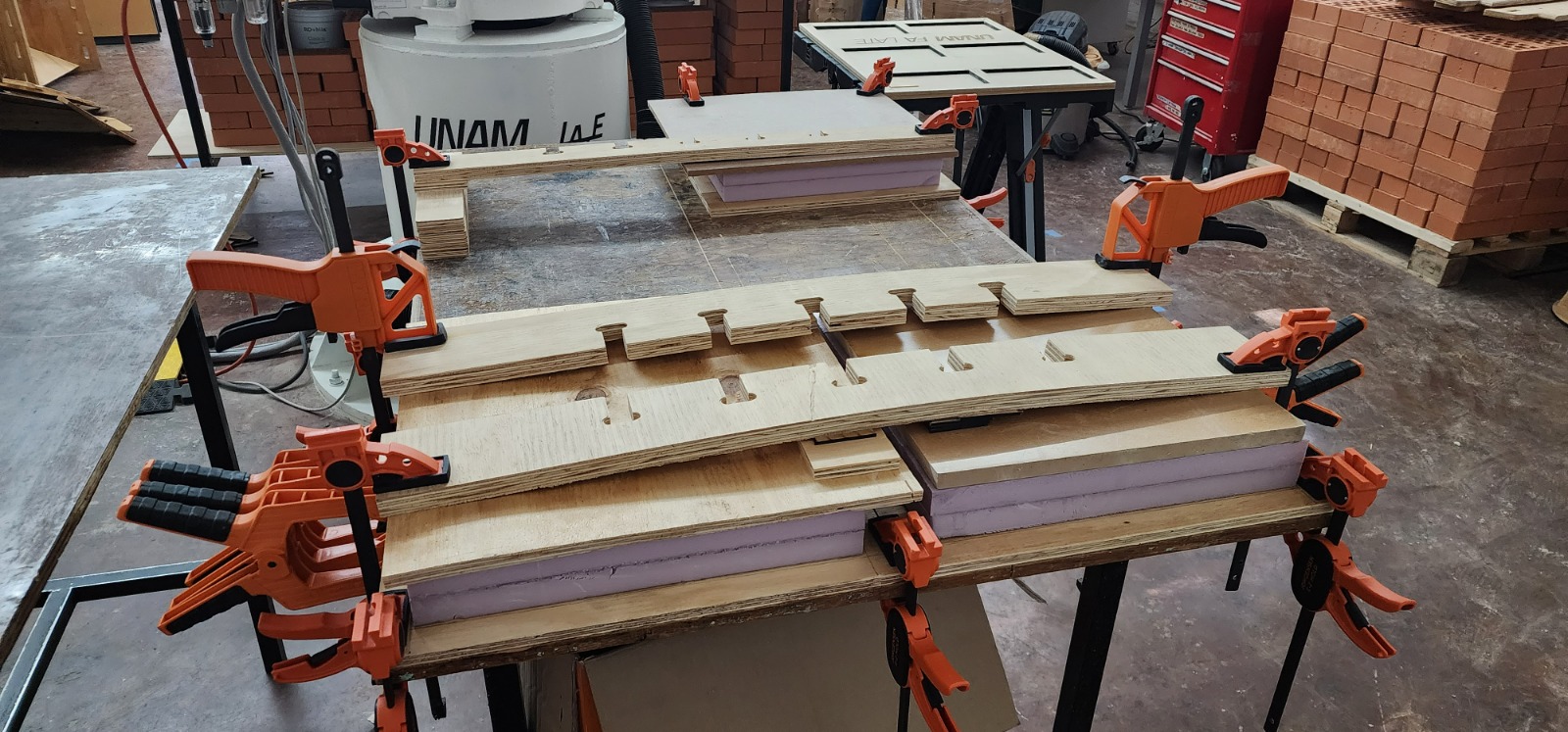
I used to different types of wood framing. Since the plywood board was very wavy, on the second frame it was better to opt for a perimetral frame instead of a continuous one.
Mixing and Pouring
I followed the instructions for a polymer fiber reinforced concrete with different agregates that a PhD student and specialist in the subject gave me (besides all the material needed)
So I mixed in the following ingredients in the following order (left to right) and in the following weight proportions
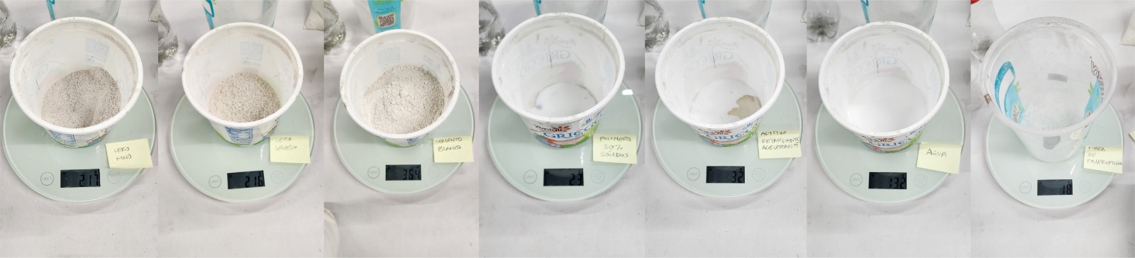
Fine marble dust · 22.48% · Cero fino
Medium marble dust · 22.48% · Cero Grueso
White cement · 37.46% · Cemento blanco
Liquid 50% solids Polymer · 2.08% · Polímero 50% sólidos
Retardant and accelerating additive · 0.31% · Agregado retardante y acelerante
Water · 13.32% · Agua
Polypropylene fiber · 1.87% Fibra de polipropileno
The consitency I obtained was this:
On the second mix (gray) I had a thicker consistency, although adding water helped to solve the problem.
I spread some automotive oil in the molds as a release agent
Then I poured a first white mix in one mold, about 1.5kg (estimated) And then in the second mold I poured the darker mix.
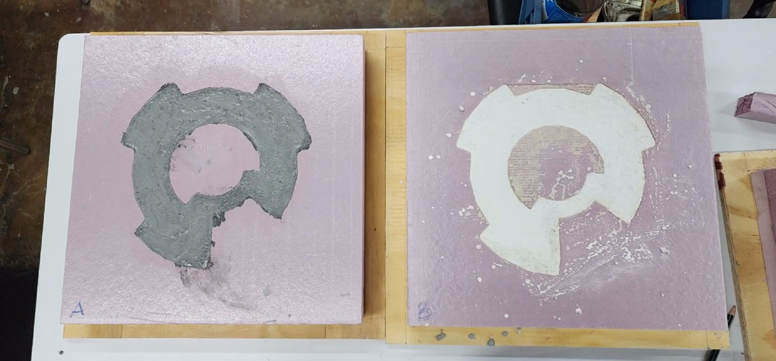
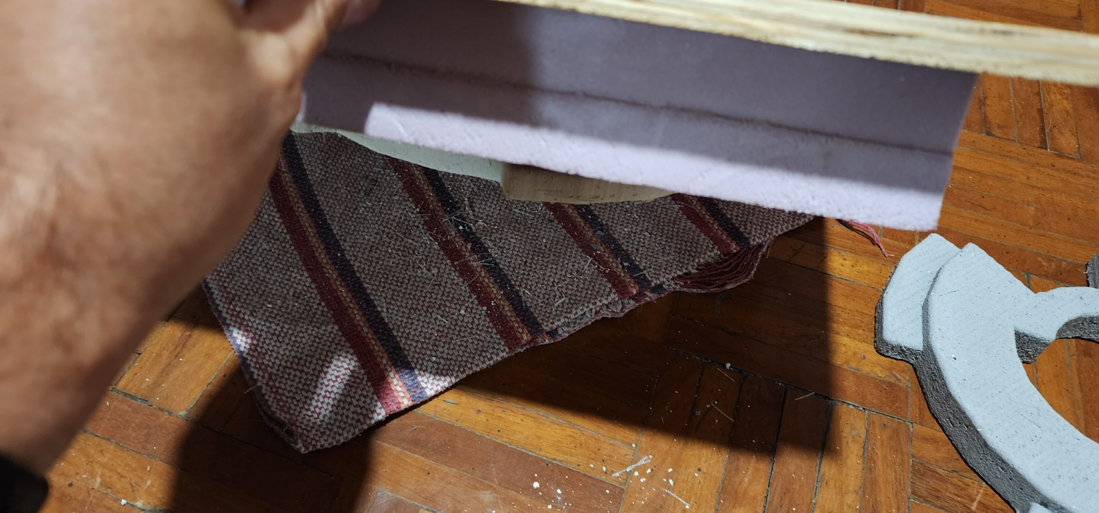
I left the molds to set for 24h then I tilted and tapped firmly but gently to get the pieces out
Individual pieces
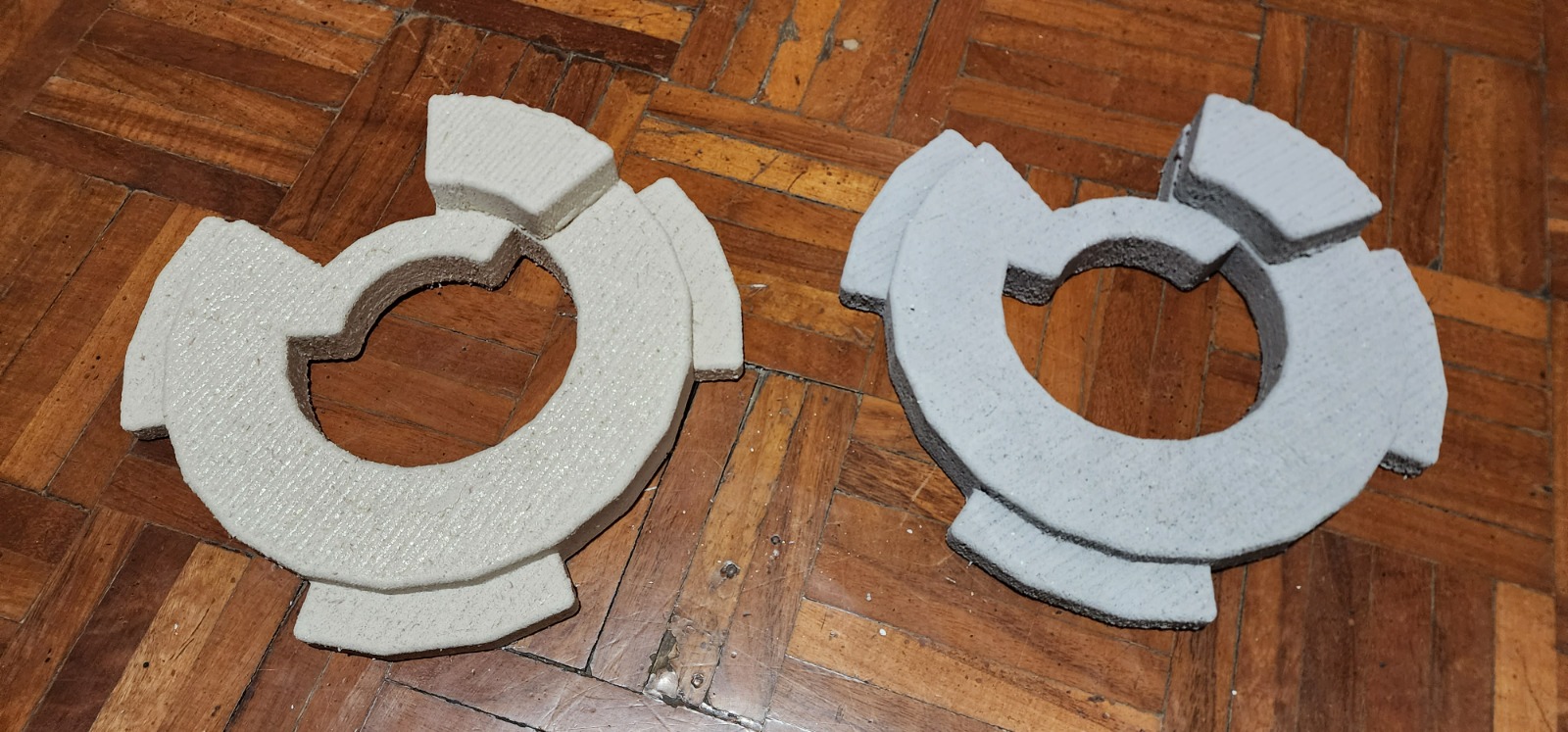
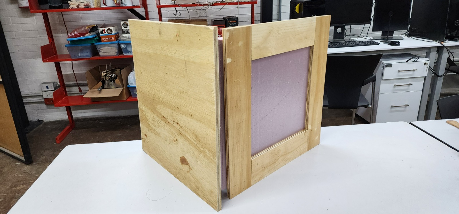
And finally and succesfully the pieces pilled and working fine together as an atractive weight!!
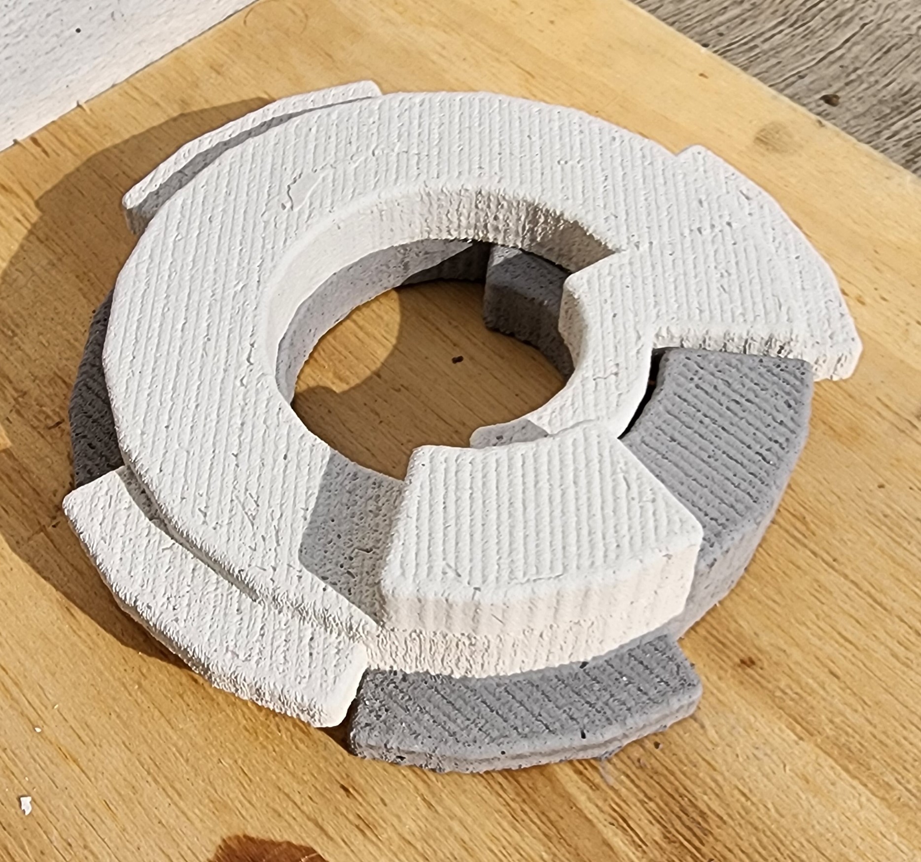
ABB Robotic Arm Routines for milling the mold
New mold with smooth curved surfaces
As a natural evolution of the weights for the robotic bench I iterated the design, this time instead of planar interconnecting surfaces with soft curved surfaces, that aim at interconnecting as well.
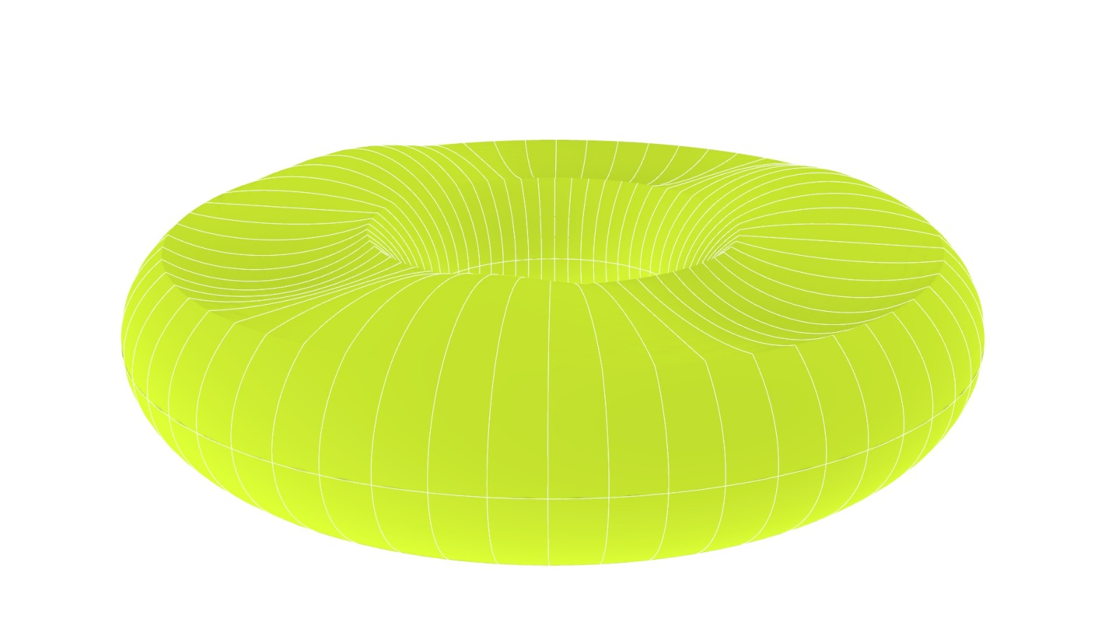
It has three bumps up and three alternating bumps down
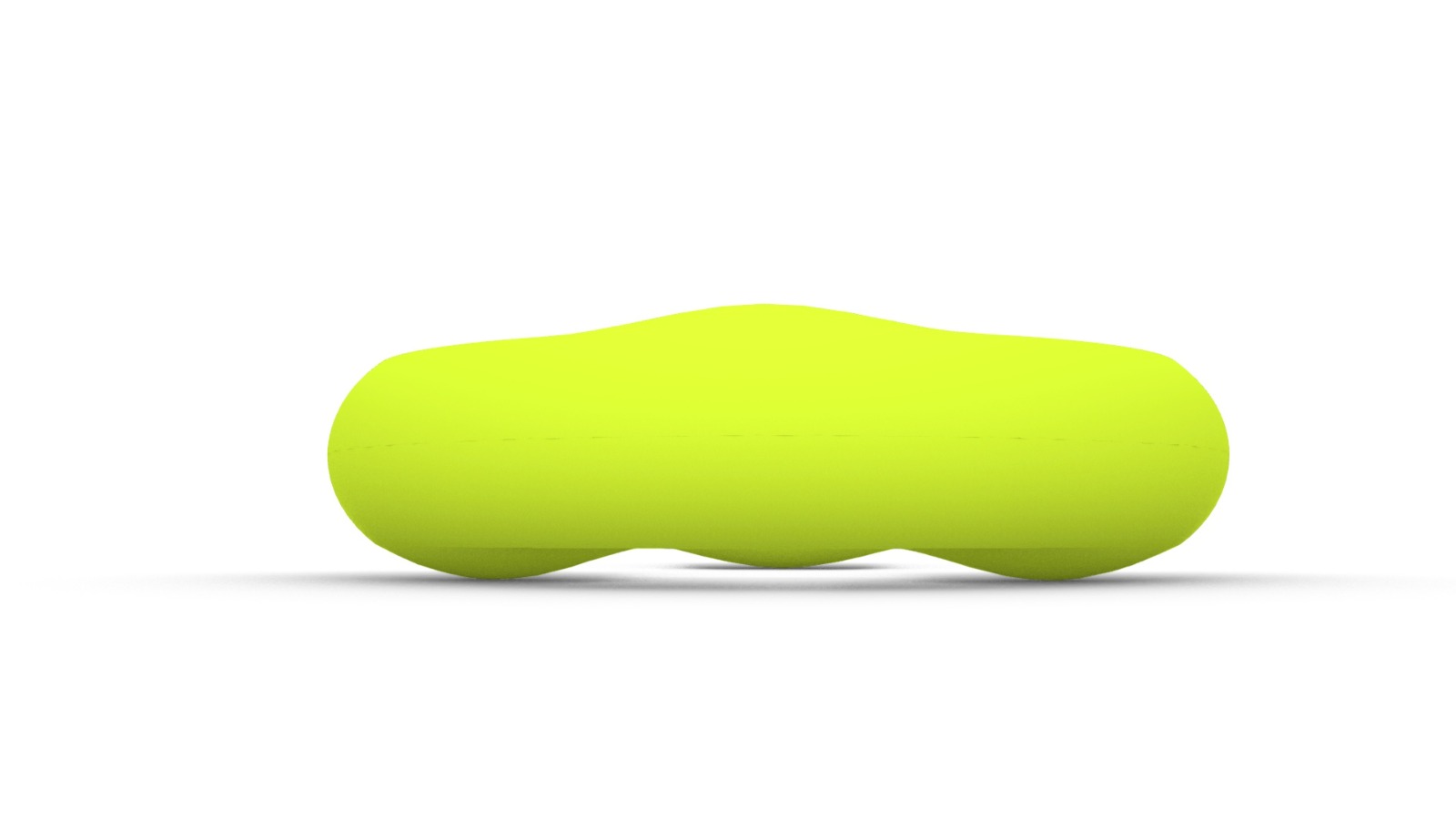 Bumps are opposed from upper and lower layers, therefore the weight will go down in the first weight directly in the three supports.
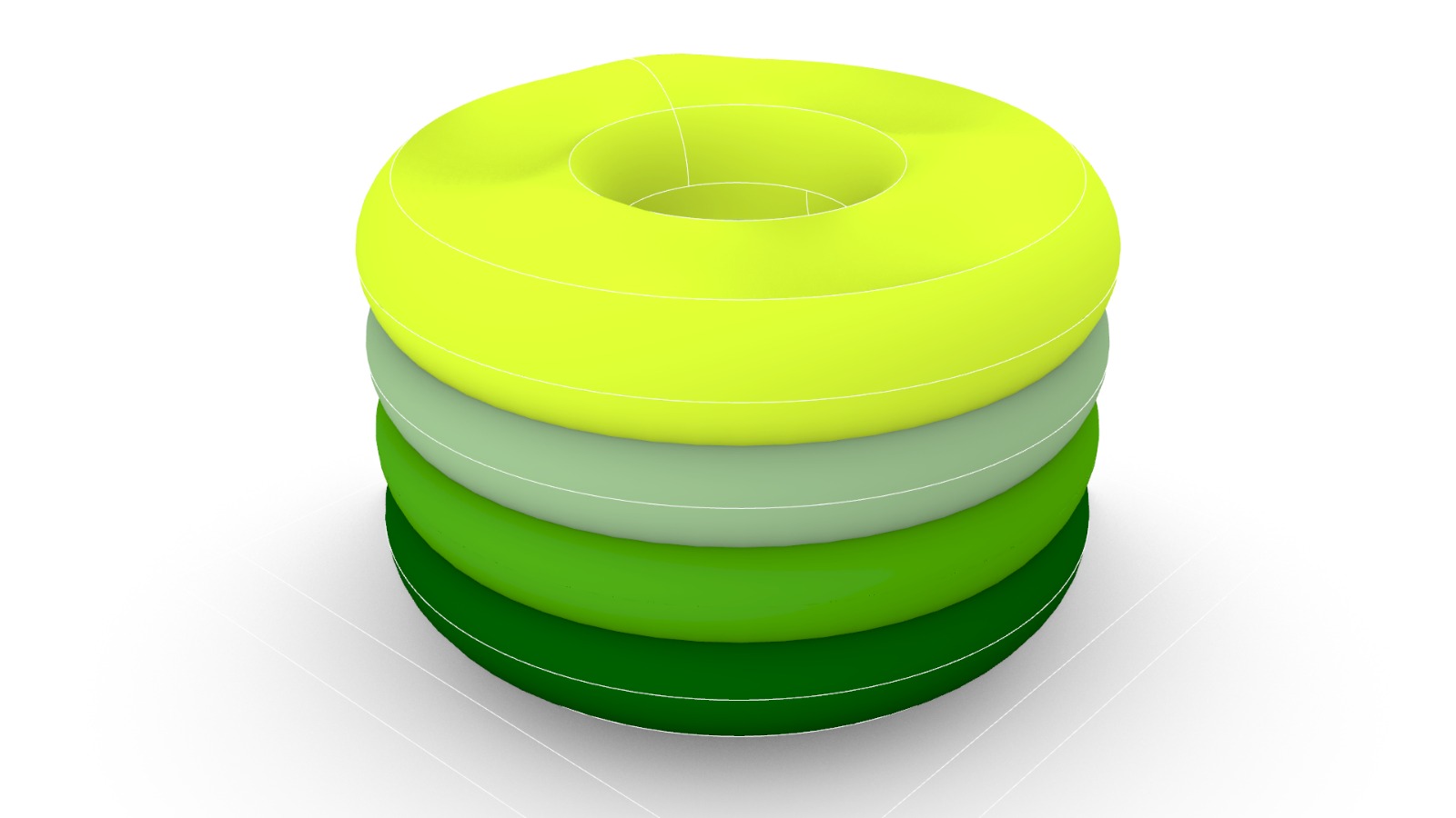 The alternating bumps allow interconnection and stacking of different ring modules.
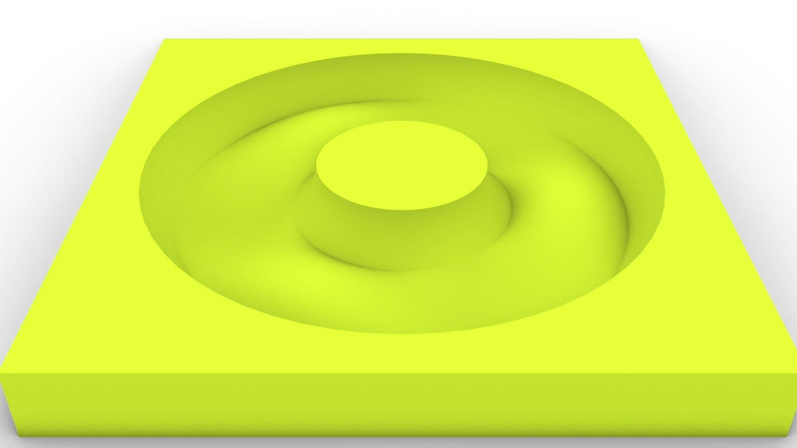 One half should be casted at a time, so its hollowed out of a block that slightly oversizes the mold size, in this case I’m going to use 2 foamular boards of 2.5cm thick and squares 35cm per side
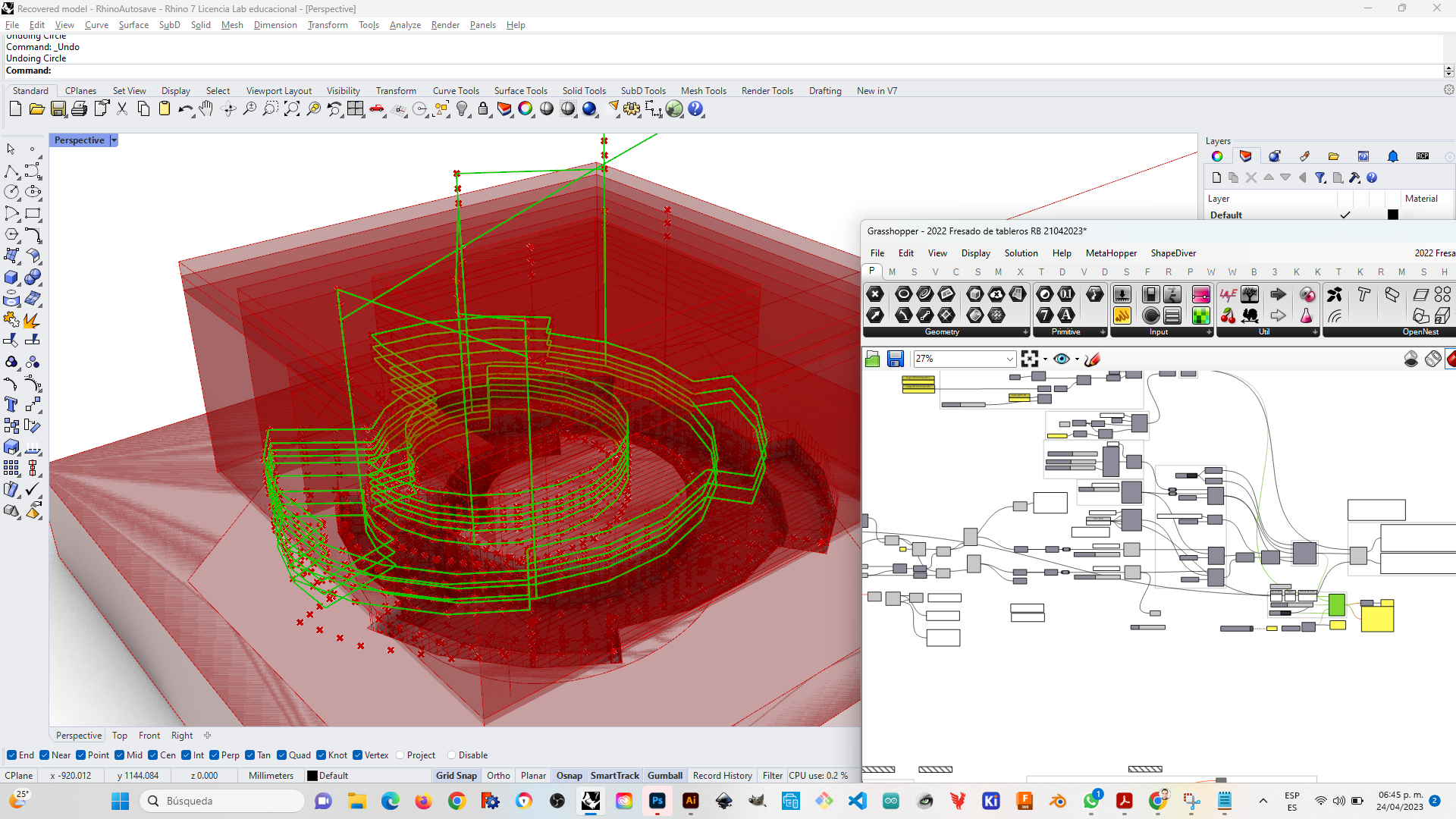
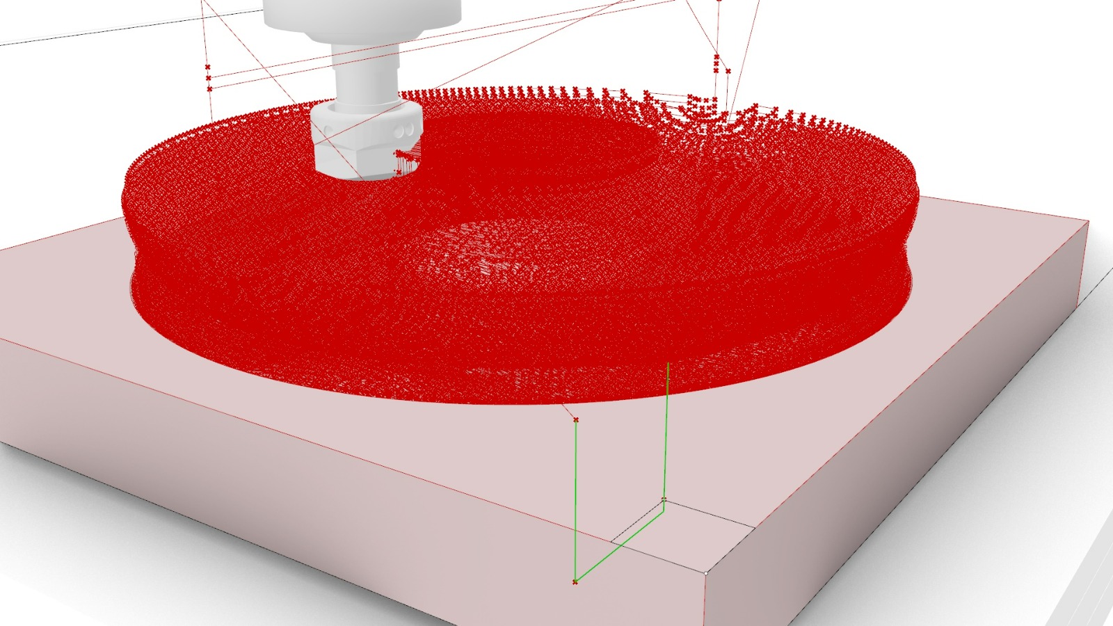 I traced three different tracks for milling, the first is a z height proof in one corner
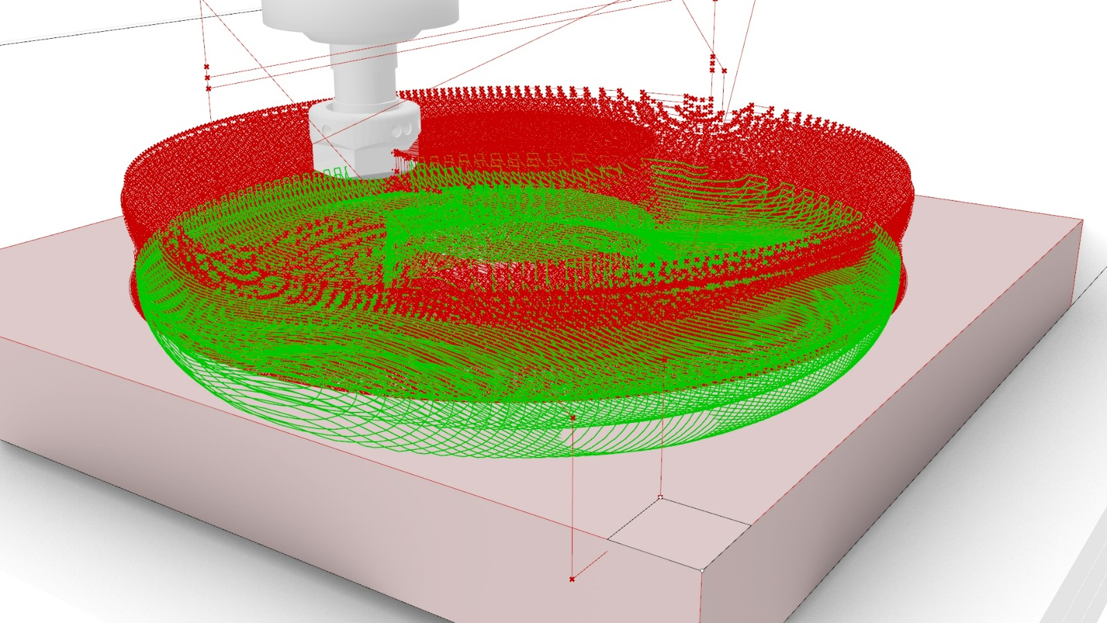 The second set is a zigzag parallel rouging set of tracks in multiple layers, that leave the last layer for finishing. The overlap is 1/3 of the bit diameter (1/4” = 6.35 mm, Amana Tool 46294-K CNC Spektra Extreme Tool Life Coated SC 2D and 3D Carving 0.10 Deg Straight Angle Ball Nose x 1/4 D x 1/8 R x 1-1/2 CH x 1/4 SHK x 3 Inch Long x 2 Flute Router Bit) the feedrate is set to 50 mm/s and the layer height is set to 1 bit diameter (later I chose to eliminate alternating layers due to code line capacity in the robotic arm = 65k lines max.)
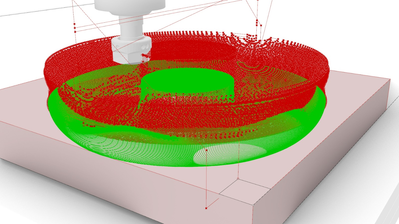 The third set is a zigzag parallel finnishing layer with an overlap of 75% of the bit diameter, same feedrate speed in 50 mm/s
The spindle for milling was set to 12,000RPM. Above, the finishing layer.
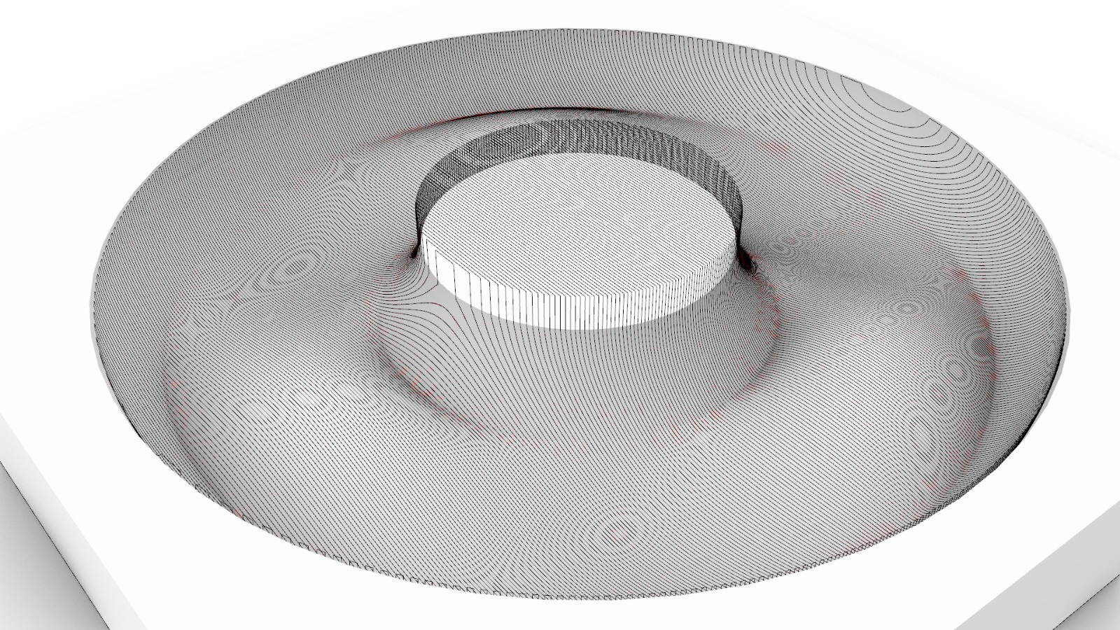 Finishing tracks
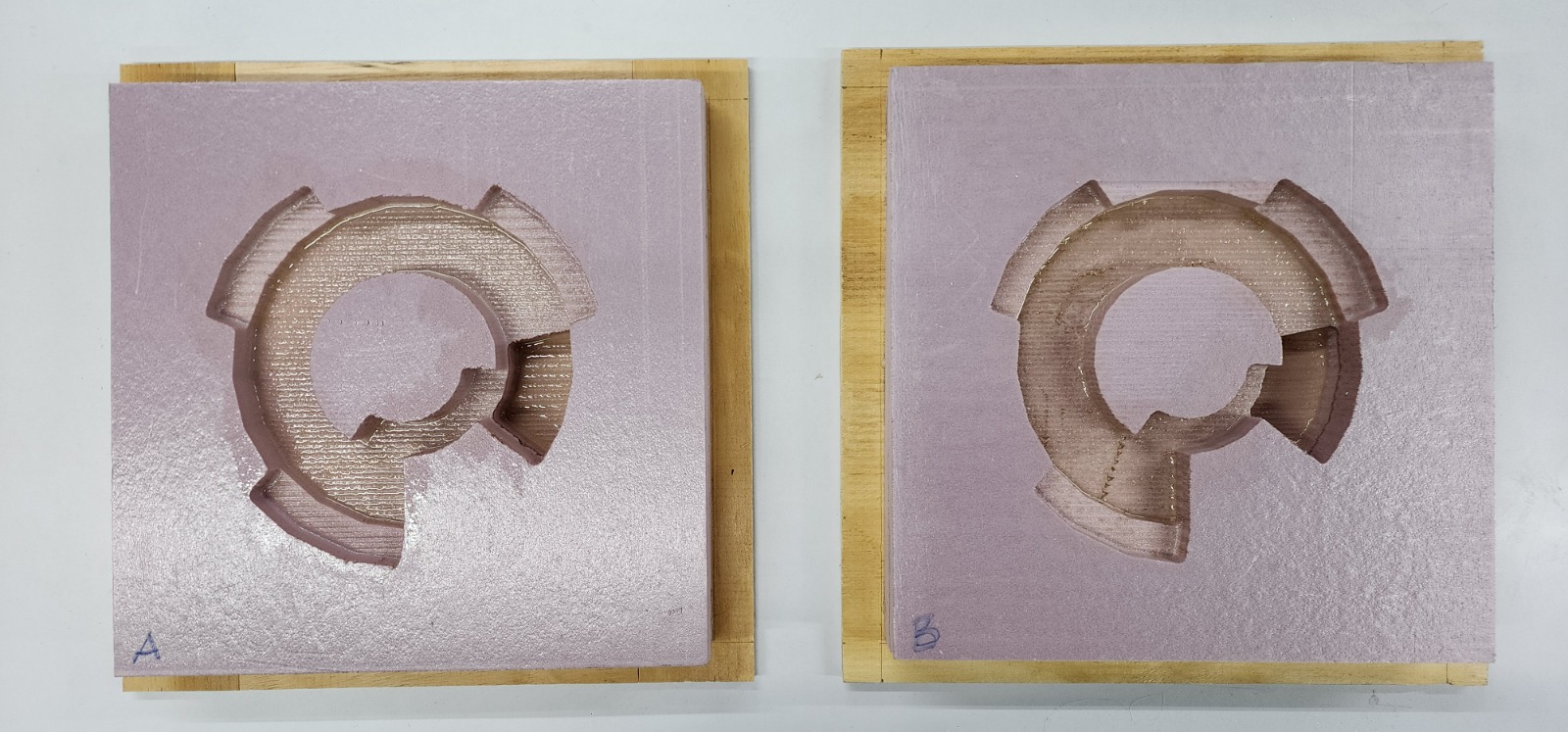
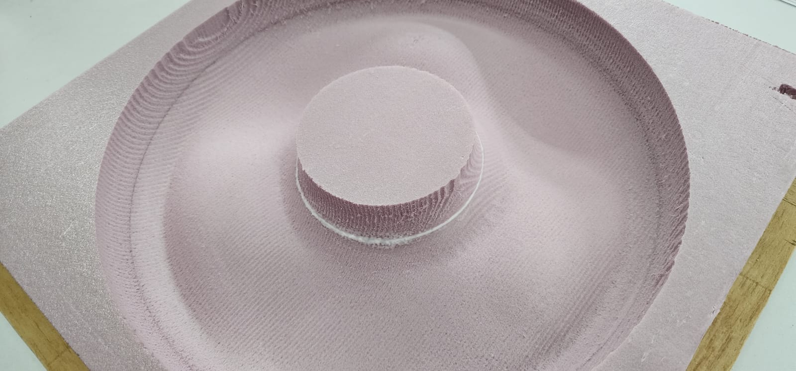
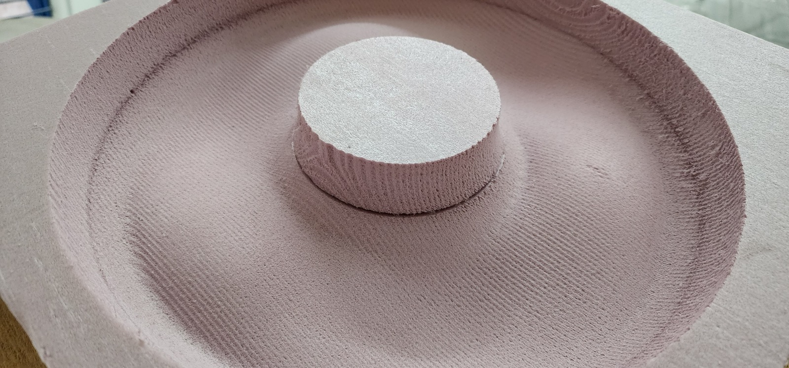 Finished mold
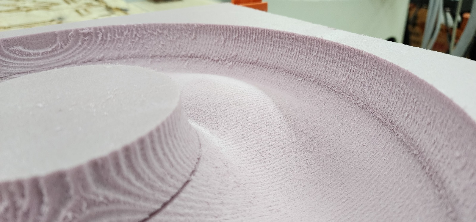 Finished mold detail
 Board union gap filled
Added the same fibercement mix previously detailed in this section, and some automotive oil in the mold as a release agent.
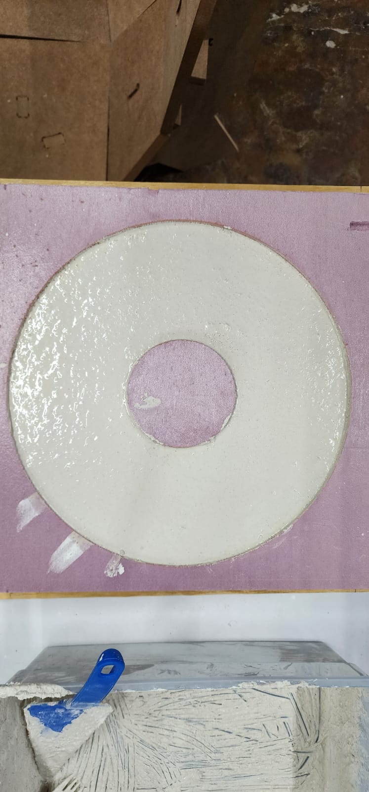 The mold already poured awaits to get dry for next day
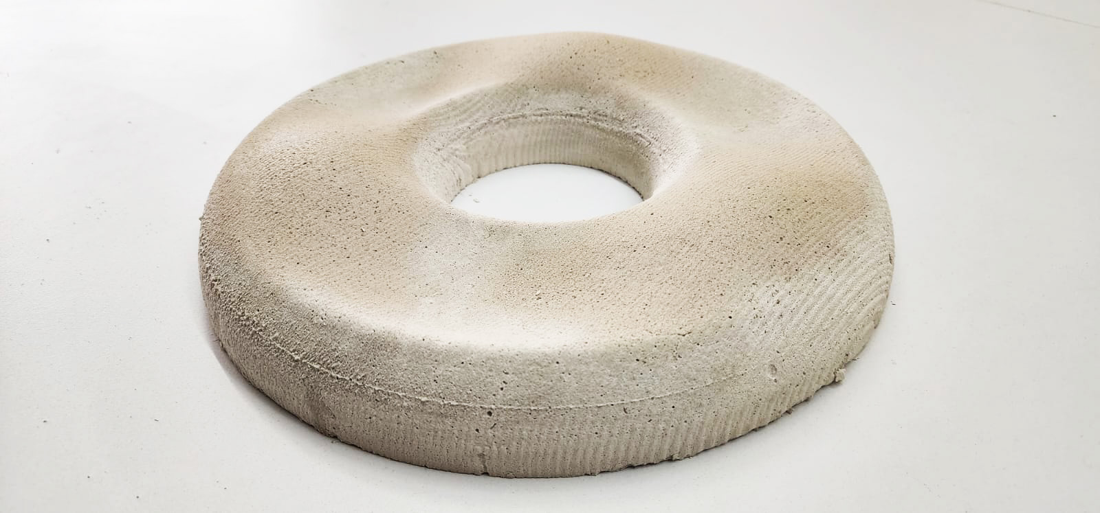 First piece casted
I want to thank Brandon, Diego and Diana (LATE trainees) for helping me out in different tasks and a special thanks goes to Jose Luis E. Miranda who helped with the mix expertise, with instructions and material, right on time.