10. Output devices

Week 10 · 2023.03.22-2023.03.29
This week I worked on putting together some electronics that will help me to acomplish my final project.
- [x] Linked to the group assignment page
- [x] Documented how you determined power consumption of an output device with your group.
- [x] Documented what you learned from interfacing output device(s) to microcontroller and controlling the device(s).
- [x] Documented your design and fabrication process or linked to the board you made in a previous assignment.
- [x] Explained the programming process/es you used.
- [x] Explained any problems you encountered and how you fixed them.
- [x] Included original design files and source code.
- [x] Included a ‘hero shot’ of your board.
Research
I went through the different Mosfets available in Fablab CDMX
- MOSFET N-ch 30v 1.7A NDS355AN
- MOSFET P-CH 30V 1.1A NDS356AP
- MOSFET P-CH 50V 16A RFD16N05LSM9A
- MOSFET N-CH 30V 90A SUD50N03-06AP-E3
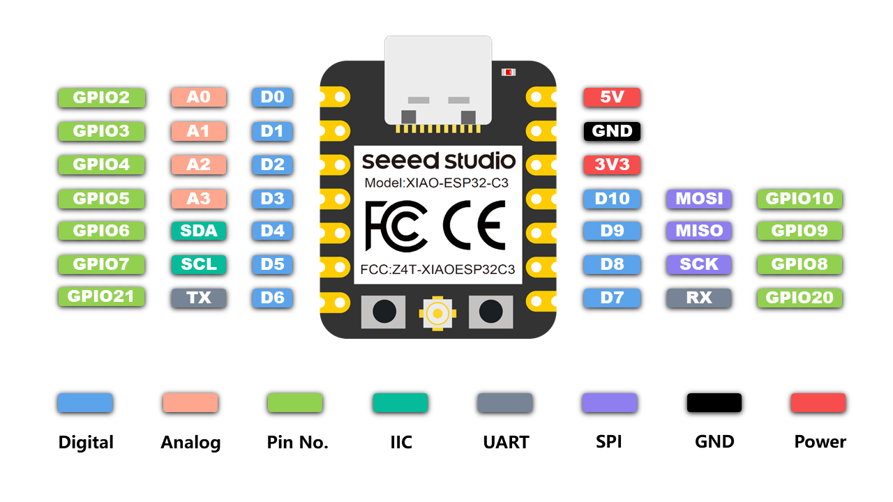
Setting the fab XIAO interchangable board
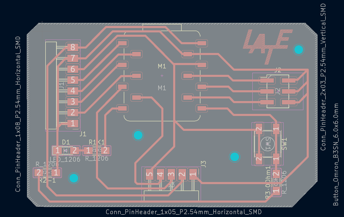
First we need to set the design or variant we will use, this may be done in Eagle or KiCAD, the latter has become the best (opensource) option for us.
The main difference with that set up by Adrian Torres is that this design includes pin sockets in order to exchange the XIAO (with vertical pins soldered) ESP32C3 with the RP2040.
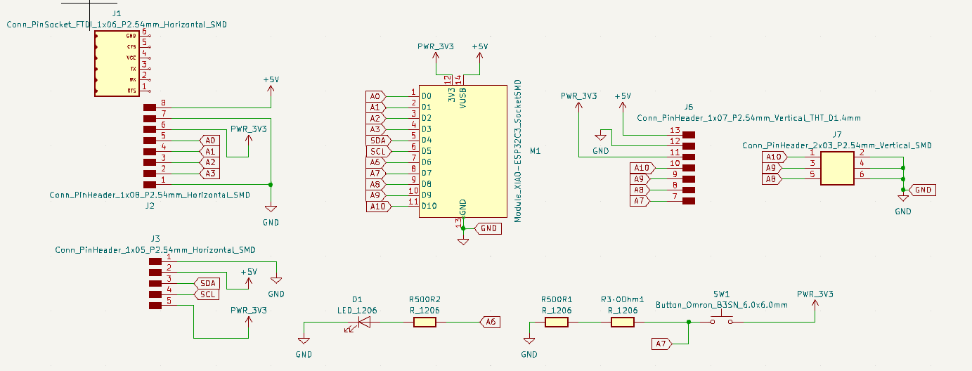


XIAO Board KiCAD file
XIAO Board KiCAD Schematic design file
XIAO Board KiCAD Board design file
Then I though this would be a good moment to kickoff our (LATE’S) Bantam Milling Machine.
Pre-Processing G-Code for Milling with the Bantam Milling Machine
After following the unboxing and basic setup for the Bantam Milling Machine linked here
You must download and install the latest Milling Software it will check for the latest version of firmware.
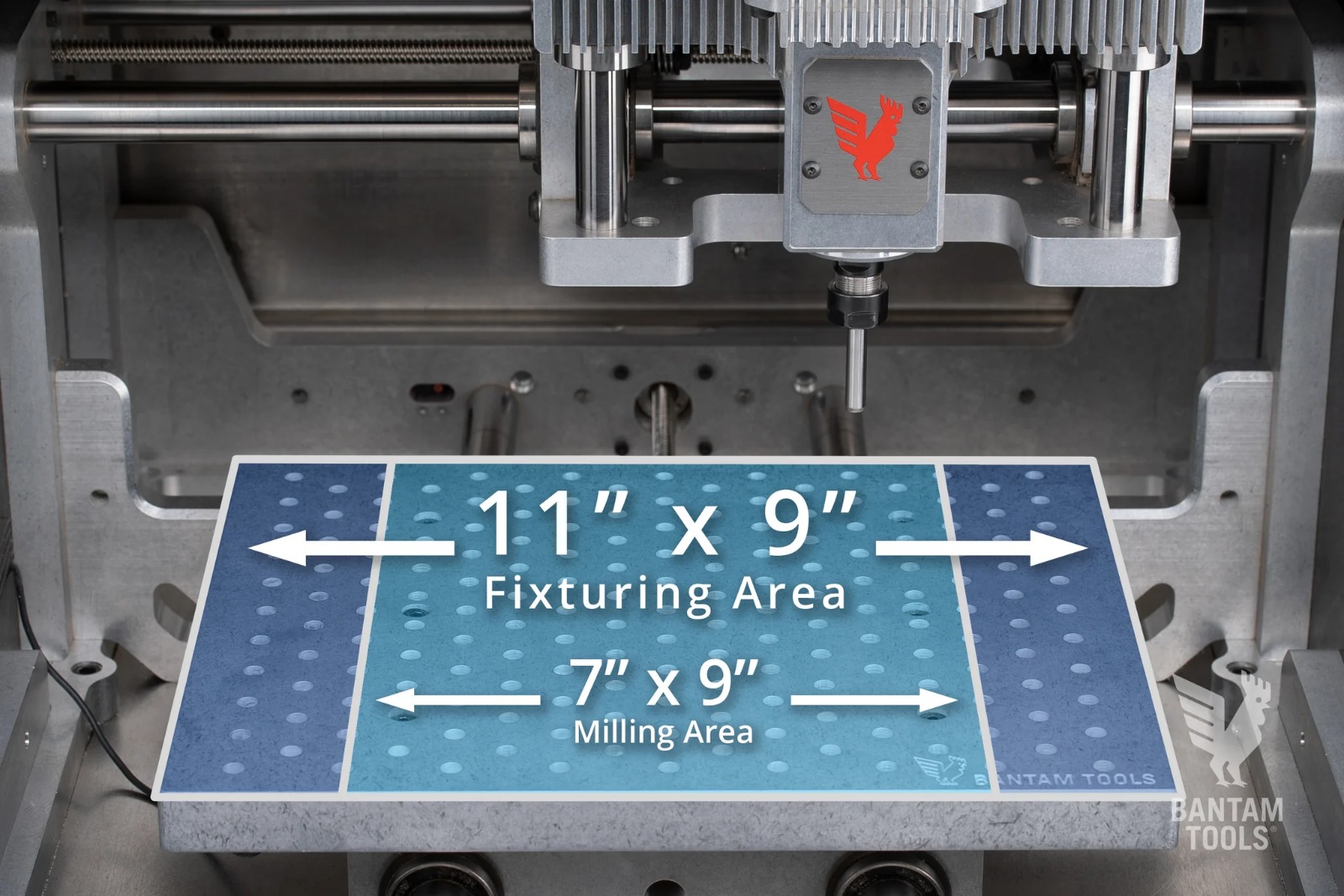
It is time to set up our upgrades acquired, such as the fixturing pallet by removing the T-Slot table. We also decided to integrate a sacrifice board made of recycled acrylic, which fits the fixturing pallet and it screws tigth in the border holes (left open for this purpose) while it blocks the rest of the holes avoiding small pieces to fall into them. Since we knew the lower right corner is used for automatic measuring of the z coordinate with the tool, we left it open, it needs to touch the metal to properly work.
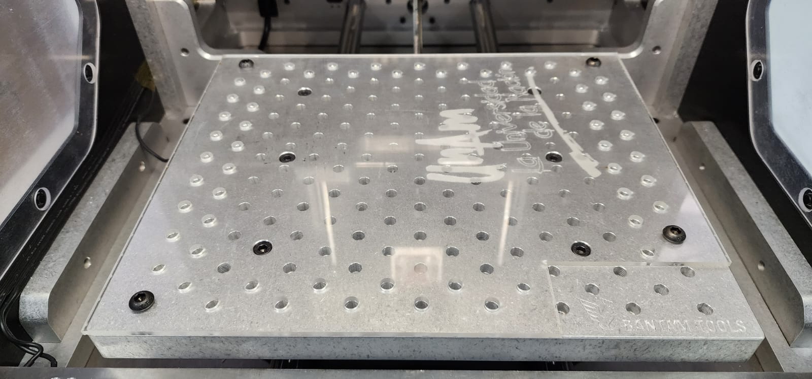
Then the phenolic board was fixed with double sided adhesive tape, placed trying to match parallel with the sorrounding edges, while it is within the working area (which is smaller to the fixturing pallet).
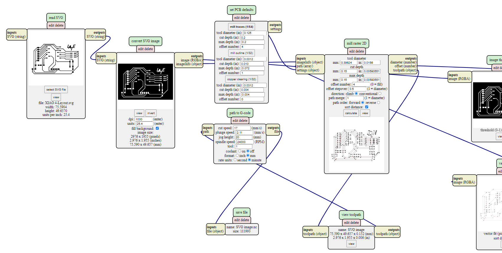
In order to have ready the file for milling it might be processed in Mods althought I used the version found in the CBA Mods
- Right click on the canvas
- Choose programs / open server program / machines / G-code / mill 2D PCB svg
- Load svg Layout file created by KiCAD
- In the second module (convert SVG image) select invert, be sure that the dpi set are 1000
- In the third and fourth module make sure that mill traces is selected (although we wont use a 1/64” bit but a Harvey piramidal 60º bit, it works pretty much the same)
- Change the cut depth and max depth from 0.1016 to 0.15mm
- Click on calculate
- Then choose where to save the .nc file
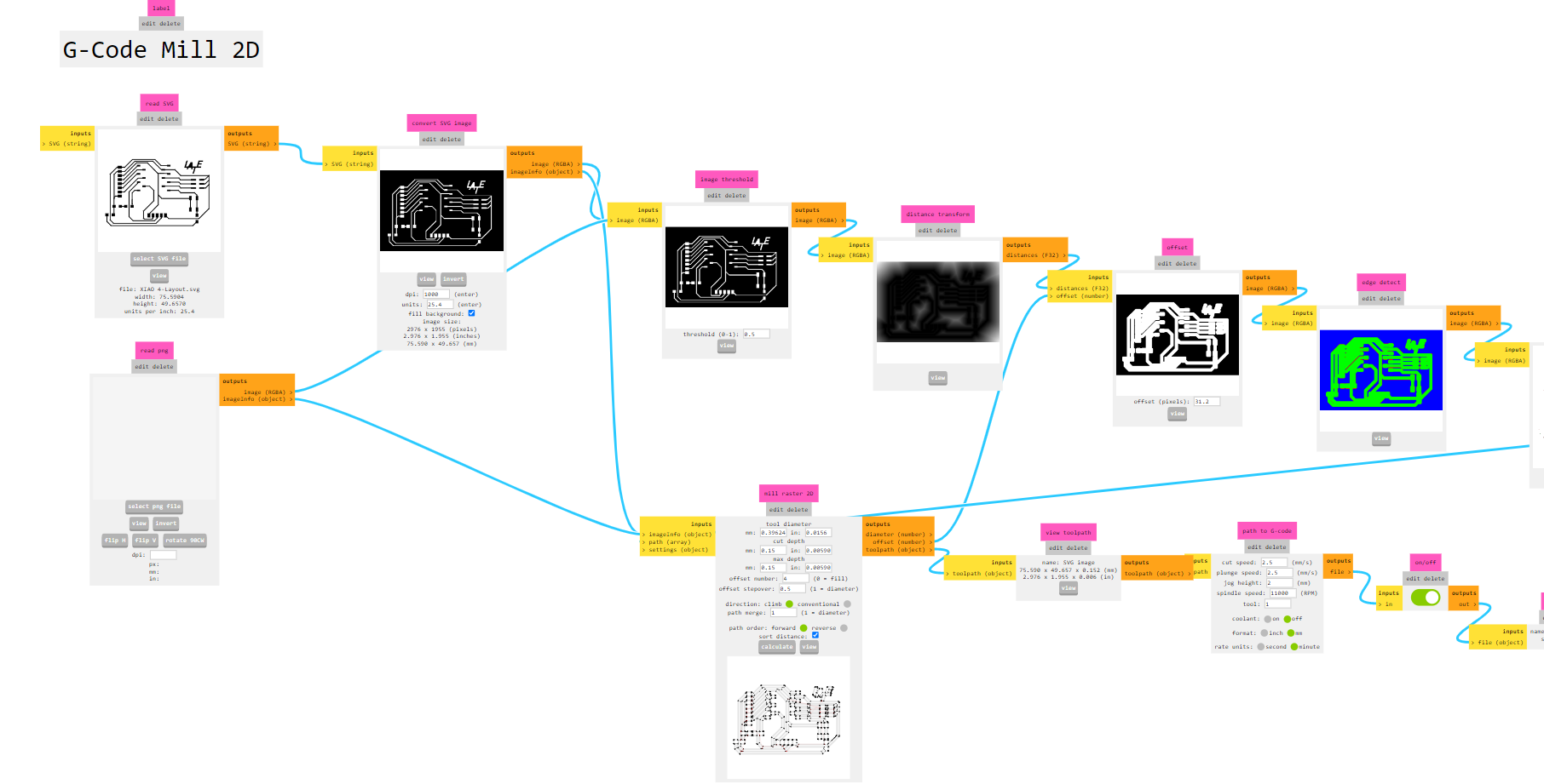
It works pretty much the same in the new mods version:
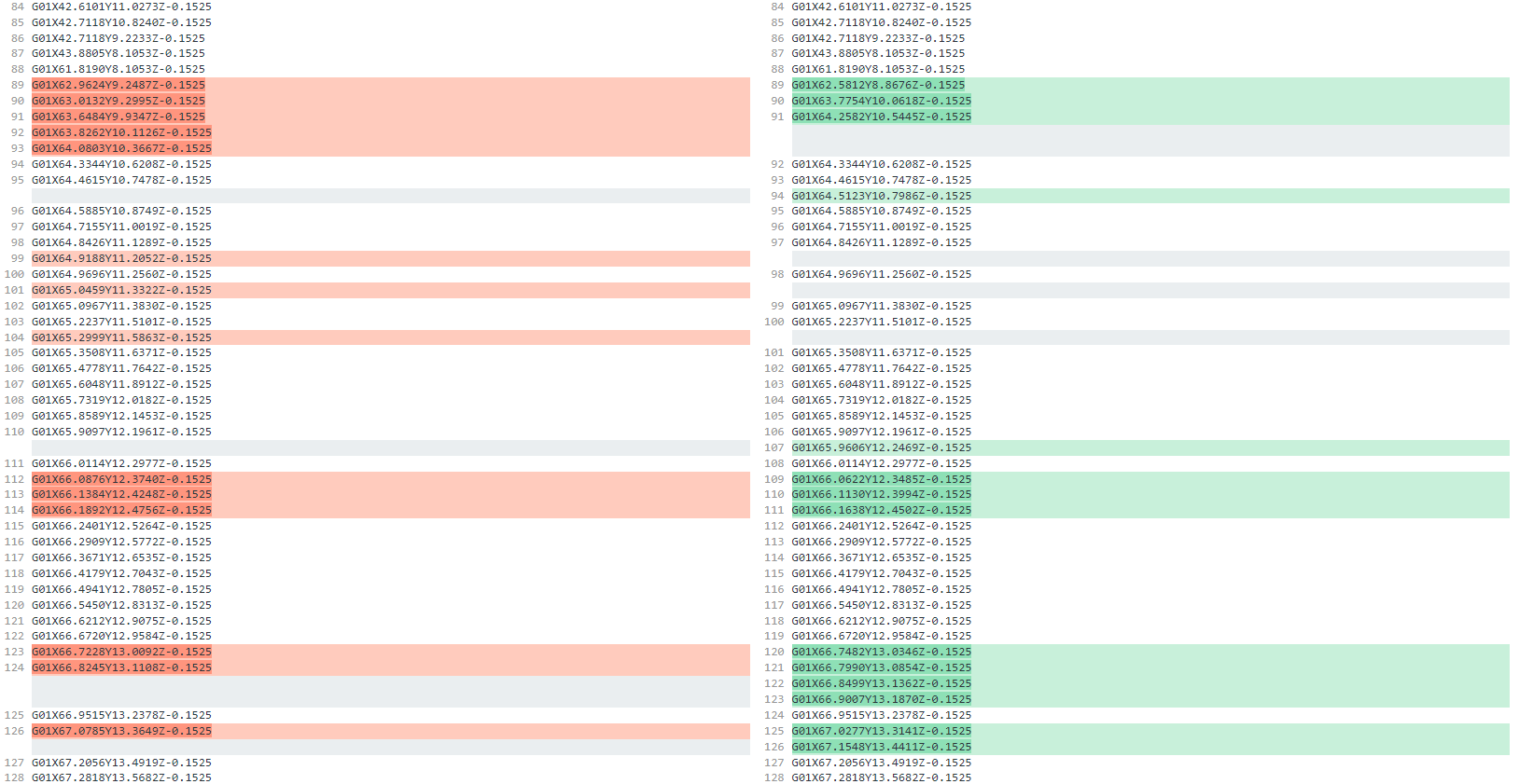
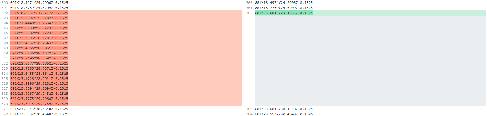
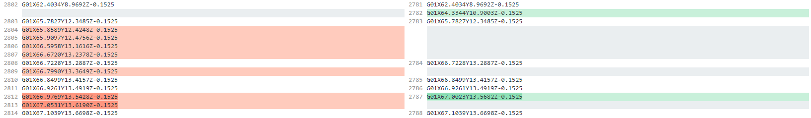
In order to compare both files you can use Difference checker and there are some differences that might be worth taking in account (finally for the milling process I have only used the old version, on the left side of the following images)
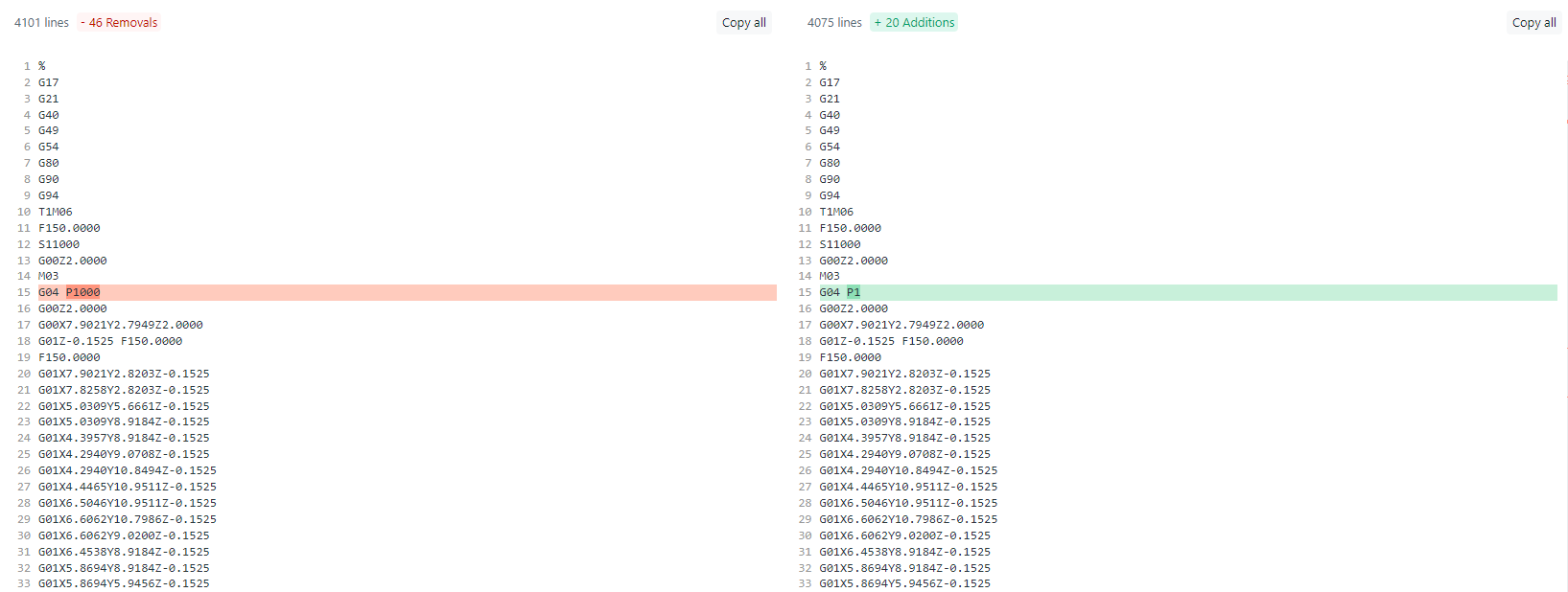


Then as far as I learned, there are some commands that don’t work properly with the Bantam that need to be modified or removed. For the Bantam Milling Machine to work properly open the file in Visual Studio Code or any other editor.
-
Remove:
- G54 (in my case Line 6)
- T1M06 (in my case Line 10)
-
Change:
- G04 P1000 to (in my case Line 15)
- G04 P10
So it ends like this:

XIAO Board layout GCode Modified file
Milling with the Bantam Milling Machine
Then we open the Bantam Tools Desktop Milling Machine Software in order to set the milling. Connect the Bantam Desktop Milling Machine to the computer and turn it on.
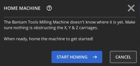
- First we need to go through the homing process
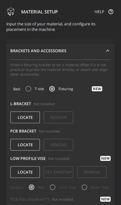
- If you acquired the fixturing pallet you may change it as well in the Bantam software, go into material setup and in brackets and accessories choose ‘Fixturing’ instead of the ‘T-Slot’ and the fixturing base will change in the 3d viewer.
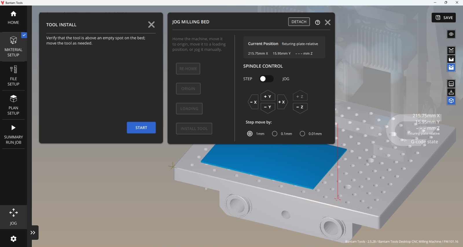
- Then start the tool install process in order to place the corresponding bit
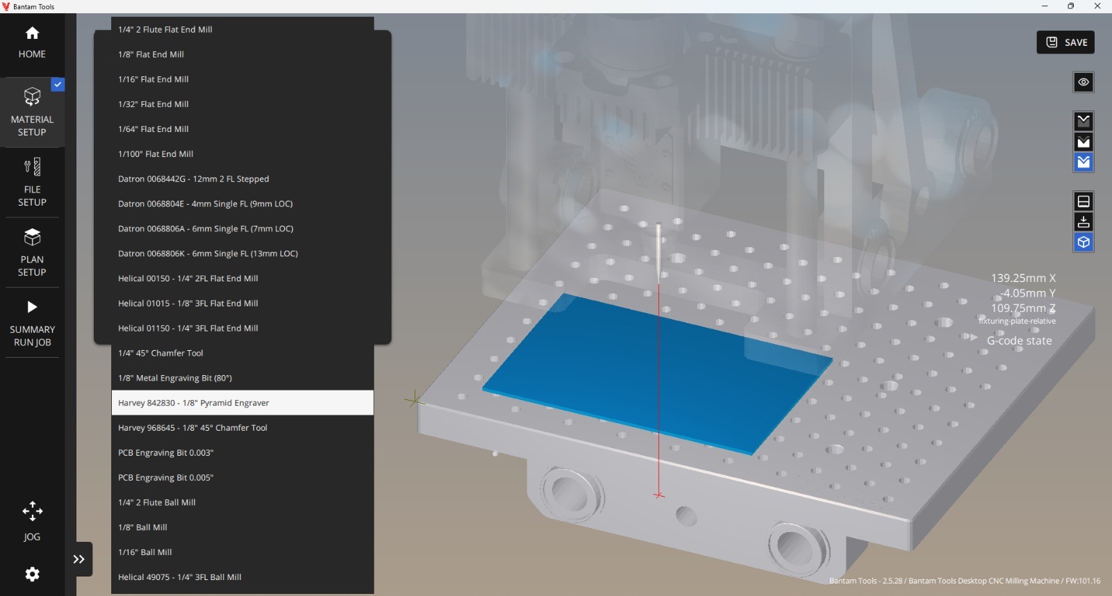
- For the general layout of the PCB we will use the Harvey 842830 - 1/8” Pyramid Engraver, install it in the spindle and choose it from the dropdown menu.
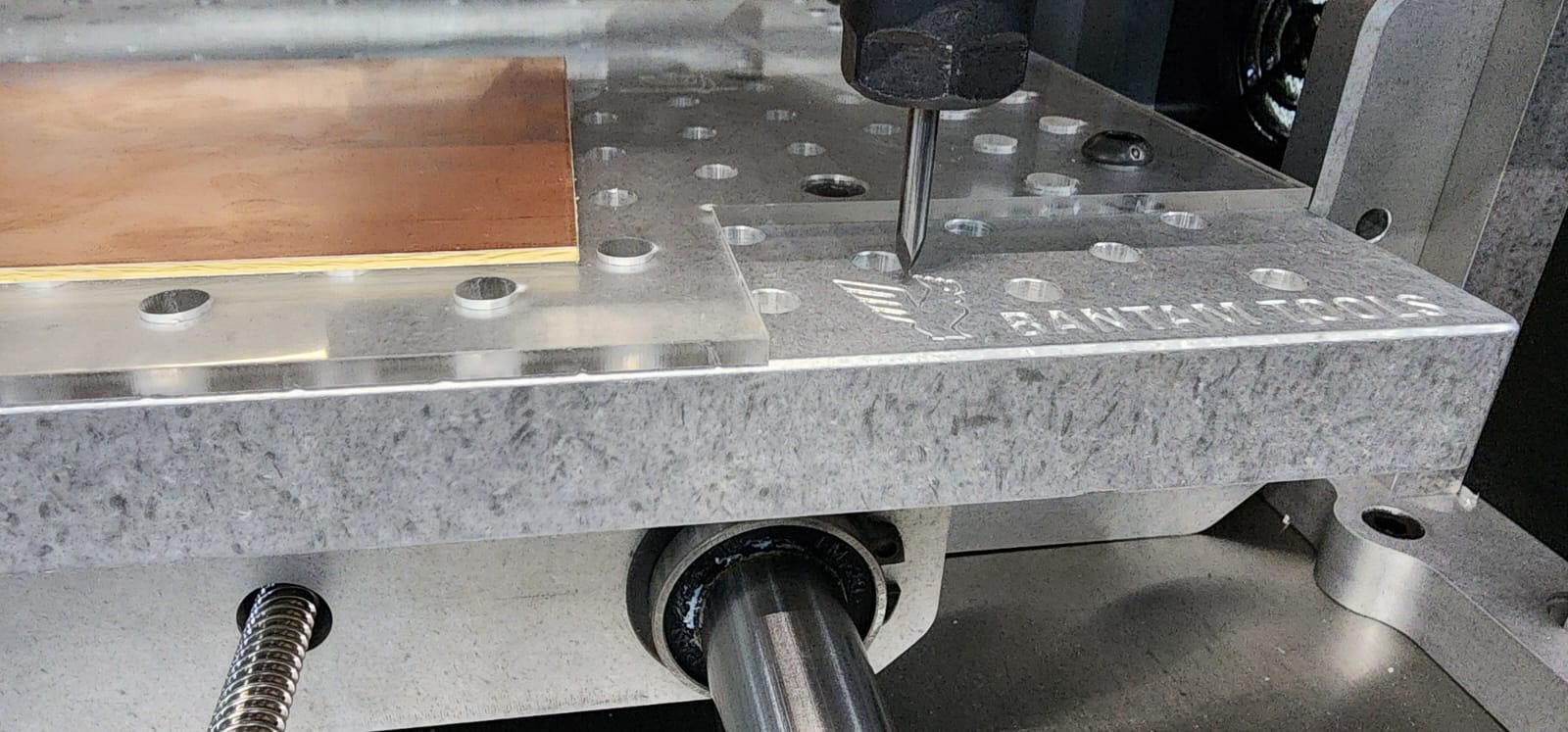
- The process includes automatic leveling for the z axis, it goes down on the back of the head of the rooster in the fixturing
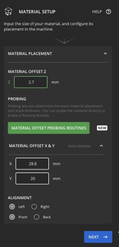
- Measure the size of the phenolic board and its distance from the border, you may use a caliper. And set this measurements in the material size menu.
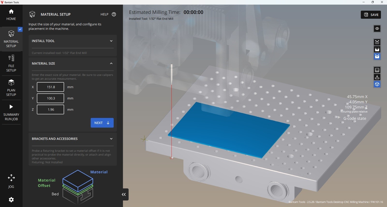
- In order to set the origin for milling, measure also the distance from the front and left edge of the pallet towards the material, and set hte offset in x and y direction, measure the height (thicknkess) of the sacrificial base for the offset in z direction and set it accordingly
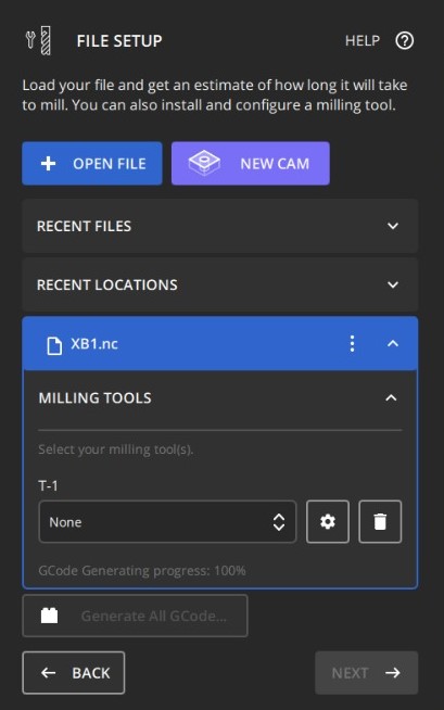
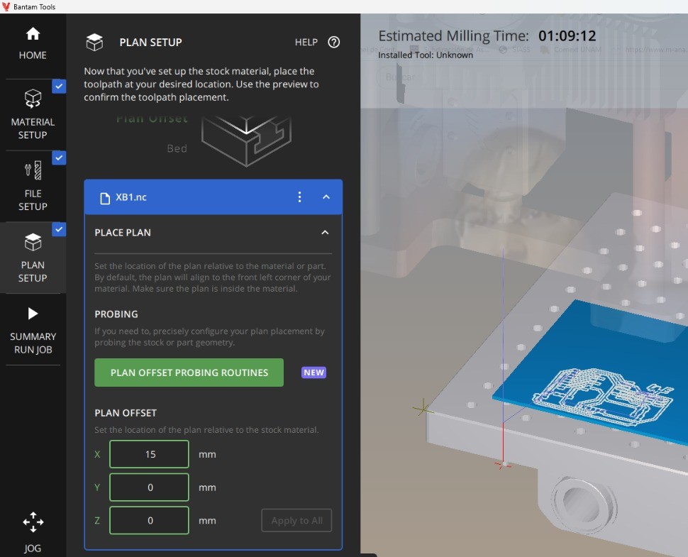
- Open the G-Code file you have previously prepared in the file setup, and again choose the mill installed for the layout
- If you ran into a red warning in the plan setup, it might mean your milling process is out of the working area
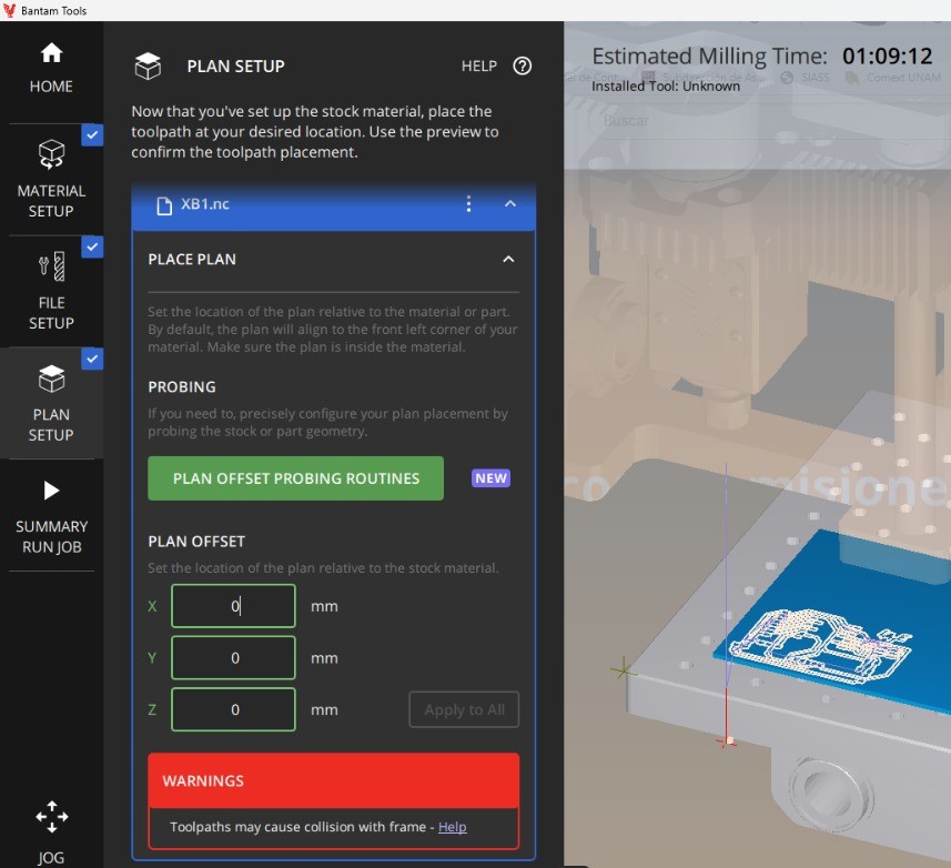
- Then shift the coordinates for placing the milling job in the working area within the material
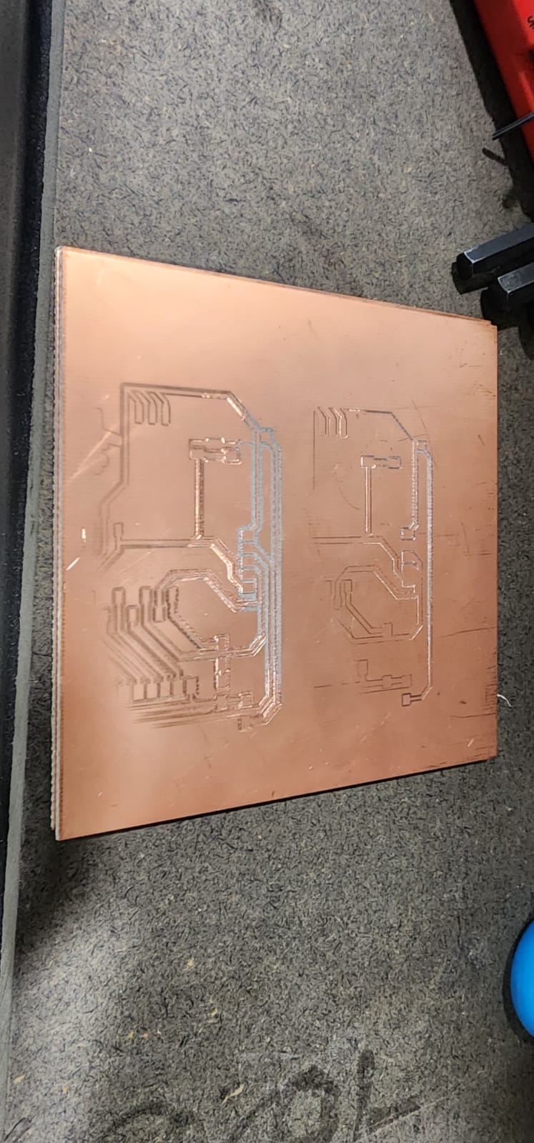
After everything has been set up, and the summary has the milling buttons enabled you are ready to run the job. Since there is only one milling process set, you may run Mill All.
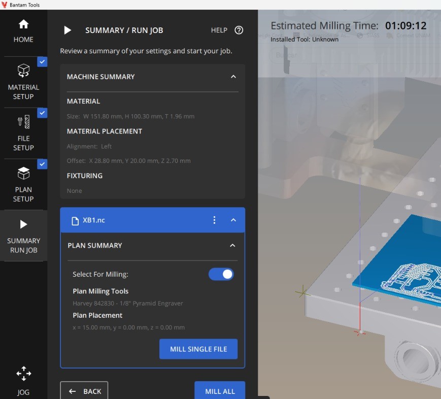
Follow the instructions and after the job is done, run the cleaning process as sugested by the software.
Following next, we need to process the outline file. - Start all over, in mods change the file for the outline, change to mill outline, and calculate again. Save the .nc file. - Check and modify the .nc (gcode) file in the editor used before, following the same steps. - In Bantam software change the milling bit to the 1/32” Flat end (change the physical bit in the spindle and change it also in the software), set the same distances as before, and mill.
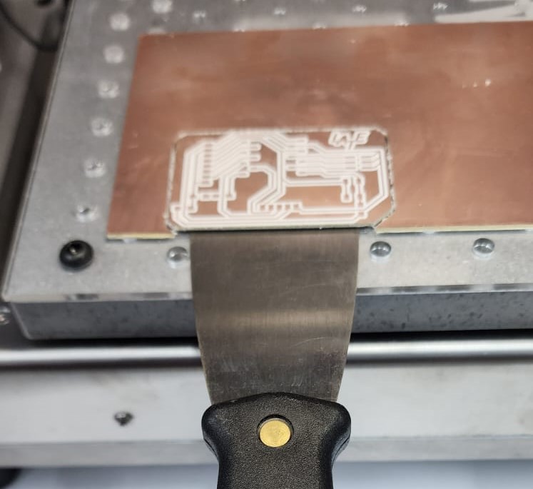
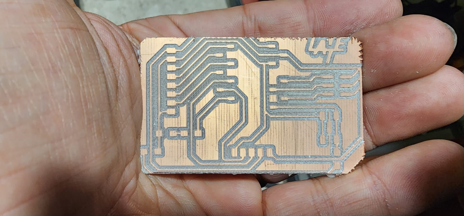
After milling has finished take it out with a spatula.
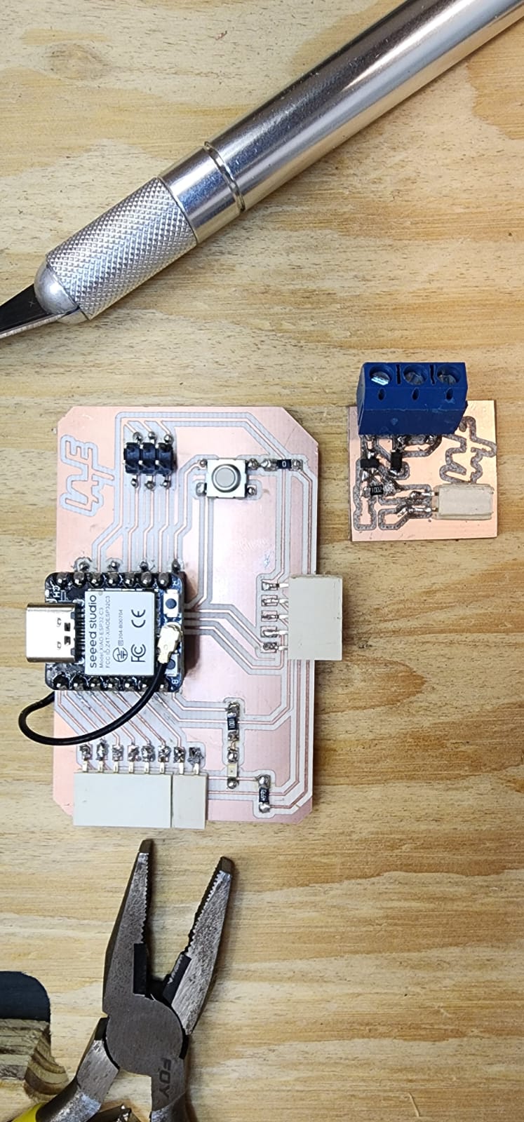
Solder the components.
After having ready your output developer board, put together the output shield that will mediate for output action.
Blink by clicking the aditional button
I used Adrian Torre’s code for blinking with a button, and changed the pins according the ESP32C3 recommendation.
//Fab Academy 2023 - Fab Lab León
//Button + LED
//Fab-Xiao
//
//Original code:Neil Gershenfeld 12/8/19
// This work may be reproduced, modified, distributed,
// performed, and displayed for any purpose, but must
// acknowledge this project. Copyright is retained and
// must be preserved. The work is provided as is; no
// warranty is provided, and users accept all liability.
//


const int ledPin1 = D6;//first light  RP2040 pin 0 or ESP32-C3 pin D6
const int buttonPin = D7;// button pin  RP2040 pin 1 or ESP32-C3 pin D7
int buttonState = 0;//initial state of the button
int i = 0; //variable intensity led

void setup() { //declaration of inputs and outputs
  pinMode(ledPin1, OUTPUT);
  pinMode(buttonPin, INPUT);
}
void loop() {
  buttonState = digitalRead(buttonPin);// we read the state of the button
  if (buttonState == HIGH) { //if we press the button
  digitalWrite(ledPin1, HIGH);
  delay(500);
  digitalWrite(ledPin1, LOW);
  delay(500);
  digitalWrite(ledPin1, HIGH);
  delay(500);
  digitalWrite(ledPin1, LOW);
  delay(500);
  digitalWrite(ledPin1, HIGH);
  delay(2000);
  digitalWrite(ledPin1, LOW);
  delay(1000);

}
  else {  //if we don't press the button
  digitalWrite(ledPin1, LOW);
  }
}
Actuating with relays (update)
After advancing for some weeks, even after networking and communications, and after a couple of mosfet board designs I came back to make some work done with relays.
So any distance measured under 25cm with the ultrasonic sensor triggers relay number 1 in the shield and as an example I placed a motor with a 9V source.
The code I developed has a tweek, since instead of running an Output pin HiGH or LOW, I found out that it was better to change the pinmode from input to output and that made it actually work.
I developed this code over the one I put together on the networking and communications week.
/*
  Ronan Bolaños based upon:
  ESP-NOW Demo - Transmit + Relay
  esp-now-demo-xmit.ino
  Sends data to Responder

  DroneBot Workshop 2022
  https://dronebotworkshop.com
*/

// Include Libraries
#include <esp_now.h>
#include <WiFi.h>

// Variables for test data
int int_value;
float float_value;
bool bool_value = true;

//Variables for declaring pins for distance sensor, relay and led
const int trigPin = D0;
const int echoPin = D1;
const int relay1 = A2;
const int led1 = D6;
int relaymode = INPUT;


//Variables for calculating distance
long duration;
int distance;

// MAC Address of responder - edit as required
uint8_t broadcastAddress[] = {0x34, 0x85, 0x18, 0x05, 0x8E, 0xF0};

// Define a data structure
typedef struct struct_message {
  char a[32];
  int b;
} struct_message;

// Create a structured object
struct_message myData;

// Peer info
esp_now_peer_info_t peerInfo;

// Callback function called when data is sent
void OnDataSent(const uint8_t *mac_addr, esp_now_send_status_t status) {
  Serial.print("\r\nLast Packet Send Status:\t");
  Serial.println(status == ESP_NOW_SEND_SUCCESS ? "Delivery Success" : "Delivery Fail");
}

void setup() {

  // Sets the trigPin as an Output
  pinMode(trigPin, OUTPUT);
  // Sets the echoPin as an Input
  pinMode(echoPin, INPUT);
  pinMode(led1, OUTPUT);
  pinMode(relay1, INPUT);
  digitalWrite(relay1, HIGH);

  // Set up Serial Monitor
  Serial.begin(115200);

  // Set ESP32 as a Wi-Fi Station
  WiFi.mode(WIFI_STA);

  // Initilize ESP-NOW
  if (esp_now_init() != ESP_OK) {
    Serial.println("Error initializing ESP-NOW");
    return;
  }

  // Register the send callback
  esp_now_register_send_cb(OnDataSent);

  // Register peer
  memcpy(peerInfo.peer_addr, broadcastAddress, 6);
  peerInfo.channel = 0;
  peerInfo.encrypt = false;

  // Add peer
  if (esp_now_add_peer(&peerInfo) != ESP_OK){
    Serial.println("Failed to add peer");
    return;
  }
}

void loop() {

  // Clears the trigPin
  digitalWrite(trigPin, LOW);
  delayMicroseconds(2);
  // Sets the trigPin on HIGH state for 10 micro seconds
  digitalWrite(trigPin, HIGH);
  delayMicroseconds(10);
  digitalWrite(trigPin, LOW);
  // Reads the echoPin, returns the sound wave travel time in microseconds
  duration = pulseIn(echoPin, HIGH);
  // Calculating the distance
  distance = duration * 0.034 / 2;
  // Prints the distance on the Serial Monitor
  Serial.print("Distance: ");
  Serial.print(distance);
  Serial.println("cm");
  int_value = distance;

  // Format structured data
  strcpy(myData.a, "Distance measuring · LATE");
  myData.b = int_value;

  // Send message via ESP-NOW
  esp_err_t result = esp_now_send(broadcastAddress, (uint8_t *) &myData, sizeof(myData));

  if (distance <= 25) {
    digitalWrite(led1, HIGH);
    relaymode = OUTPUT;
    Serial.println("medida menor");
  }
  else if (distance > 25){
    digitalWrite(led1, LOW);
    relaymode = INPUT;
    Serial.println("medida mayor");
  }
  if (result == ESP_OK) {
    Serial.println("Sending confirmed");
  }
  else {
    Serial.println("Sending error");
  }
  Serial.println(relaymode);
  pinMode(relay1, relaymode);
  delay(1000);
}
Issues
I had to repeat many times the milling due to a myriad of reasons, such as 1. Unleveled bed, 2.Cutting the outline on the interior side instead of the outside, 3. making holes to a board (that instead of going in the circle it went around) 4. Not holding the bit tight (because the allen key is swept)
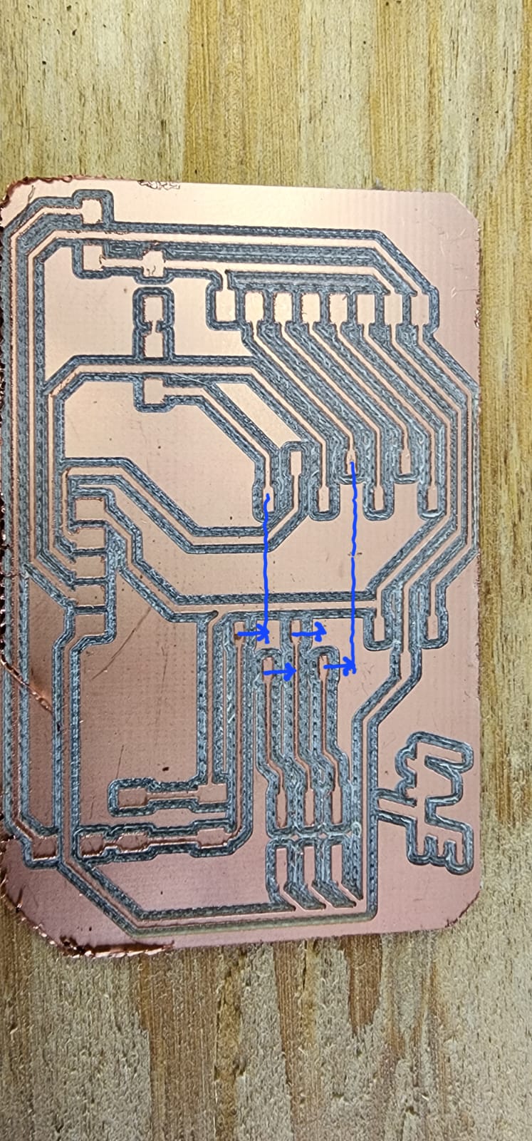
And when I was able to come up with a good milling I realized 5. my manual pin layout had half of the pins shifted one position on one side.
- Unleveled bed
- Cutting inside
- Pins shifted
Mosfet Shield
I followed the following diagram in order to use a mosfet as a switch, and then I put together the shield.
These are the files for the design of the shield:
Mosfet as a switch project
Mosfet as a switch schematic design
Mosfet as a switch pcb design


I couldn’t make the shield work as I wanted so I turned back to relays instead