Final Project
Week 20 · 2023.06.07-2023.06.14
During this week I focused on finishing my final project
- [x] Made your slide> 1920 x 1080 pixels with your name, project name, Fab Lab name, a photo/render/sketch of your project, a brief description of what your project is/does
- [x] Made a ~1 minute (10MB/1080p) video of you explaining your project
- [x] Made a separate Final Project page that briefly summarises your project
- [x] Included the BOM (Bill of Materials) for your project
- [x] Linked from this page to any weeks that you worked on your final project
- [x] Linked to your presentation.png and presentation.mp4; make sure they are located to the root of your website
- [x] Included all of your original design files in the archive (2D & 3D, board files & code)
- [x] No external hosting of final project files - discuss file sizes with your instructor
- [x] Included the license you chose
- [x] Acknowledged work done by others
Final project Documentation
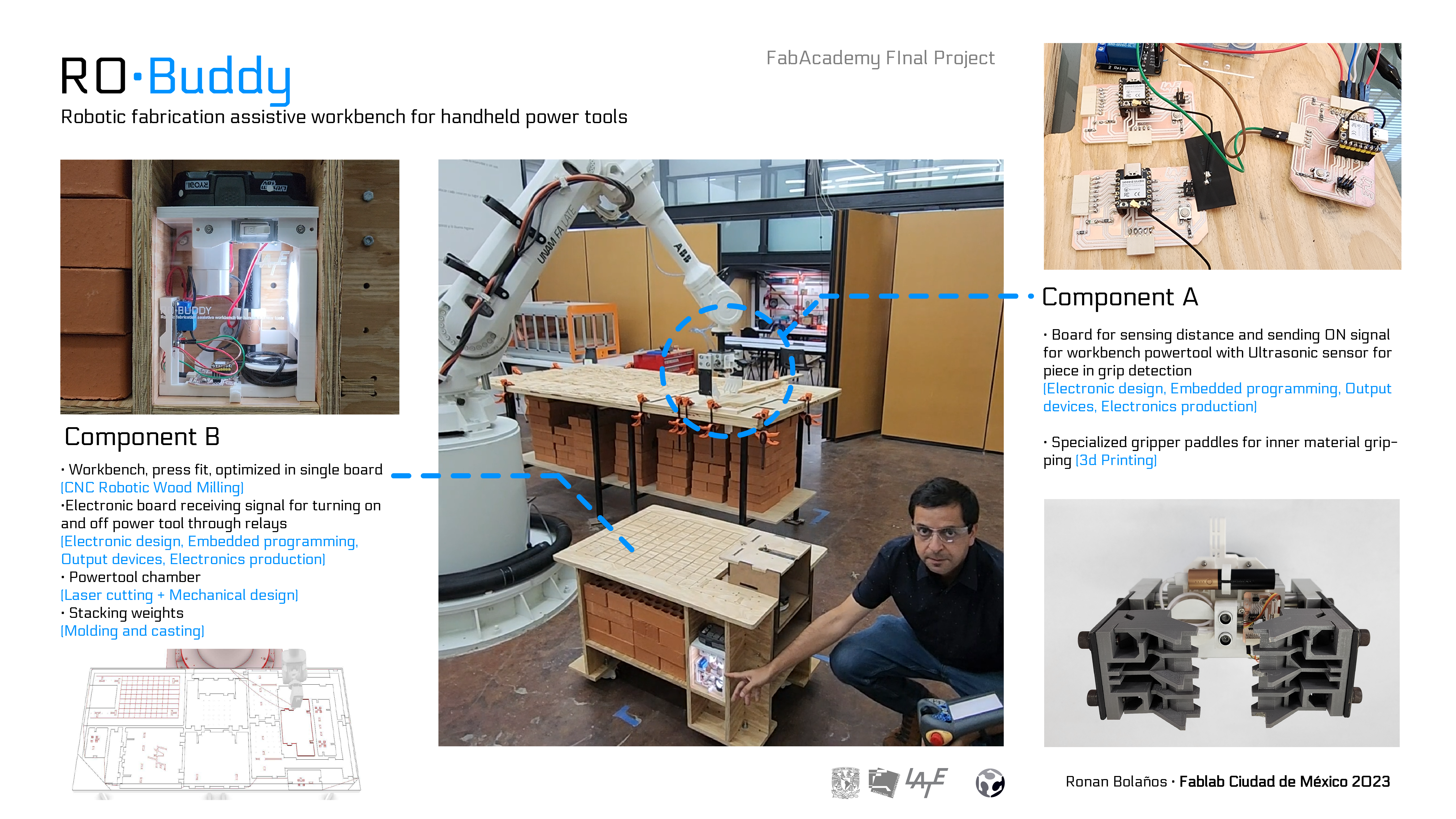
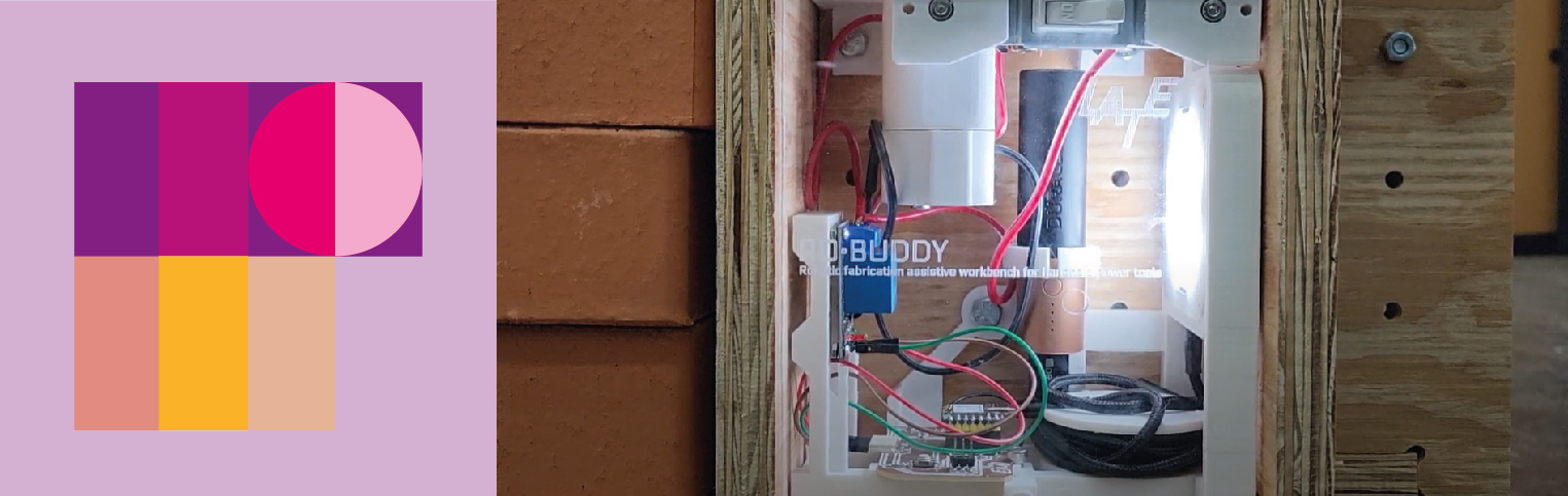
Robotic fabrication assistive workbench for handheld power tools
What does it do? I looked forward to create a workbench that can hold hanheld regular battery-powered tools for a robotic arm to actuate on them, shifting smoothly from one tool to another. For example starting with a router then cutting with a circular saw, followed by drilling some holes and then band sanding or using other tools, on the same piece.
Who’s done what beforehand? There are some research proposals that deal with how to grip a tool, there have been some colaborative processes where the robotic arm delivers or moves the material towards or away from a static tool, and some other closer developments. Information about these antecedents may be found here
What did you design? I designed it into two main components:
A. The gripper add - ons · I designed the paddles to grip pieces from the interior in order to process the whole perimeter of the piece. For more information about the paddles click here. It also has an electronics board I designed following Adrian Torres original Xiao board For more information about the board design and production click here. This board connects to an ultrasonic sensor placed facing into the gap between the paddles. The board sends a wireless signal to another board in the second component.
B. The workbench · I designed this second component as pressfit workbench with a horizontal surface of 60cm x 90cm which tributes a gesture for the measurment of a regular plan size in architecture which oftenly have these measurements. The workbench was set to be milled with our robotic arm, in a single 122cm x 244cm board with a thickness of 18mm. The nesting initially was done with the aid of the Open Nest plugin for Grasshopper by Petras Vestartas. This component includes a case for electronics and a drawer for fixing different handheld power tools. The drawer is a modular box that allows to fix firmly a specific handheld tool, and could be changed easily.
The electronic case hosts another electronic board copy of that of the gripper with the same XIAO ESP32C3 chip, this board receives the signal of the length measured by the ultrasonic sensor from the gripper board and compares the distance with the thresshold which is set to 15cm, if its under this value it sends a signal to the relay shield that stands in between a switch and the female adapter of the battery. When the relay gets turned on it passes energy to the male connector of the power tool in the drawer, allowing it to turn on automatically (depending on the tool) or manually if there is a security mechanism that requires so. For more information about the board programming click here
What materials and components were used? I 3D printed with PLA the structure for the gripper add ons, the electronic case in the workbench and the male and female connectors for the battery. I used 18mm plywood for the workbench. 9mm MDF, 12mm plywood and 3mm acrylic (reused from pandemics) for the drawer, as well as some metallic mechanic elements. An ultrasonic sensor, two XIAO ESP32C3 based boards, a relay shield, two Duracell power banks, a gopro 5 camera and a light (both mainly to drain the powerbanks, since the power consumption from the boards was not enough to keep them on for long periods)
Where did they come from? Plywood and MDF was bought locally from Homedepot (imported from Chile); some electronics were provided by the fablab and others were bought through Amazon (and come from China), others were bought from Steren local stores; PLA from a local Makerbot sales representative, mechanic parts were bought through Amazon (and come from China)
How much did they cost? Originalshceweek 18
What parts and systems were made? Everything was made except for the Robotic arm and some electronics: the relay shield, the battery banks, camera, light and the ultrasonic sensor.
What processes were used? Robotic Milling, Precission Milling, Laser cutting, Electronic Production, Programming and Molding and casting weights for the workbench.
What questions were answered? The main preliminar challenges were:
a. Being able to provide a firm grip for each part while grabbed by the robotic arm · this was achieved adding more weight with bricks and holding everything firmly
b. A firm grip for the handheld tool · this was achieved
c. A precise approximation between tool and the part · also achieved
d. Being able to put together the electronics with the input comming from the robot controller · this was left for a second iteration, instead the input came from the gripper
What worked? What didn’t?
At the end everything proposed for this cycle worked, what had to be overcome was:
a. Turning Tool instead o sliding · Initially the tool harness was designed to have movement in one axis to receive small errors from the material being processed, this was set with rubber bands, but the way it moved was not really restricted to one axis in a perpendicular fashion, but it tended to rotate. So at the end a stiff wood belt had to be added to fix the position of the handheld tool.
b. Powertool Manual restart · The first tool chosen to work with the workbench is the manual router, due to the following reasons: a. I wanted to try a fillet bit to round the edges of some wood pieces, it is easier to flip the piece and not the router for processing both sides. It is also better to have a planar guide to push the material and that would have been hard for attaching to the robotic arm. While designing and building I used a drill for trying out the electric system. But when I tried with the router I found out that even whenever is fed with electric power the tool wont start unless you do a manual restart.
c. No Signal from the Robot controller · I wanted to send output signals from the robotic arm controller that would sum to the signal from the gripper, at the end this came out a little bit more complex for me so I decided to leave it out in this design cycle.
d. Non cooperative security actions from the powerbanks · I found out to late that the powerbanks I bought came with several security actions that usually end in turning off the banks. The consumption by the boards was under the regular thresshold of consumption for a power bank of this kind, so I integrated a Gopro camera on the gripper (useful of course) and a light in the workbench (with a nice and useful touch) that would help me out in draining enough power from the banks in order for them not to shut down shortly after.
e. Gripper paddle broken · Around 24h before presentation time, one of the paddles broke because of an error I commited in the trajectory of the gripper, the 3d printing time for the paddles to print together was 26h! so I sent one paddle in one printer and another on a second printer (original paddles were gray and this would print in white, that is why I would re-send both), anyway the broken paddle was glued as a backup, the printers ended after 12h and I was able to try them and adjust accordingly.
How was it evaluated?
The whole system has a firm grip so it can process pieces ☑
The electronic and electric system work continuously as designed ☑
It is a low cost solution ☑
What are the implications? This workbench is useful for experimental robotic processes such as those developed in a School of Architecture such as ours, it allows multitool serial processing instead of parallel processing with an automatic tool changer. It’s cheaper since it allows the use of the pre-existing tools, and there is no need to add new specialized tools or a tool changer. The distance and time for this kind of fabrication is shorter than that with an automatic tool changer. The fabrication of this workbench can be done in a fablab and it would take about three weeks for one person.
Final project files
Model files
Gripper:
Workbench:
- RoBuddy · Workbench
- RoBuddy · Workbench Powertool Drawer
- RoBuddy · Workbench Electronics
- RoBuddy · Workbench Electronics
- RoBuddy · Workbench Stacking Casted weight
Fabrication layouts:
Final codes
The code for the transmitter and receiver are detailed below these lines. The transmitter sends by ESP NOW protocol the measurement from the ultrasonic sensor in the gripper to the receiver which evaluates if the thresshold (under 15cm) is reached for activating automatically the relay.
Transmit code
/*
  Ronan Bolaños based upon:
  ESP-NOW Demo - Transmit
  esp-now-demo-xmit.ino
  Sends data to Responder

  DroneBot Workshop 2022
  https://dronebotworkshop.com
*/

// Include Libraries
#include <esp_now.h>
#include <WiFi.h>

// Variables for test data
int int_value;
float float_value;
bool bool_value = true;

//Variables for declaring pins for distance sensor
const int trigPin = D2;
const int echoPin = D3;


//Variables for calculating distance
long duration;
int distance;

// MAC Address of responder - edit as required
uint8_t broadcastAddress[] = {0x34, 0x85, 0x18, 0x03, 0x74, 0xA8}; // MAC Address: 34:85:18:03:74:A8 LATE XIAO Board Green Light

// Define a data structure
typedef struct struct_message {
  char a[32];
  int b;
} struct_message;

// Create a structured object
struct_message myData;

// Peer info
esp_now_peer_info_t peerInfo;

// Callback function called when data is sent
void OnDataSent(const uint8_t *mac_addr, esp_now_send_status_t status) {
  Serial.print("\r\nLast Packet Send Status:\t");
  Serial.println(status == ESP_NOW_SEND_SUCCESS ? "Delivery Success" : "Delivery Fail");
}

void setup() {

  // Sets the trigPin as an Output
  pinMode(trigPin, OUTPUT);
  // Sets the echoPin as an Input
  pinMode(echoPin, INPUT);

  // Set up Serial Monitor
  Serial.begin(115200);

  // Set ESP32 as a Wi-Fi Station
  WiFi.mode(WIFI_STA);

  // Initilize ESP-NOW
  if (esp_now_init() != ESP_OK) {
    Serial.println("Error initializing ESP-NOW");
    return;
  }

  // Register the send callback
  esp_now_register_send_cb(OnDataSent);

  // Register peer
  memcpy(peerInfo.peer_addr, broadcastAddress, 6);
  peerInfo.channel = 0;
  peerInfo.encrypt = false;

  // Add peer
  if (esp_now_add_peer(&peerInfo) != ESP_OK){
    Serial.println("Failed to add peer");
    return;
  }
}

void loop() {

  // Clears the trigPin
  digitalWrite(trigPin, LOW);
  delayMicroseconds(2);
  // Sets the trigPin on HIGH state for 10 micro seconds
  digitalWrite(trigPin, HIGH);
  delayMicroseconds(10);
  digitalWrite(trigPin, LOW);
  // Reads the echoPin, returns the sound wave travel time in microseconds
  duration = pulseIn(echoPin, HIGH);
  // Calculating the distance
  distance = duration * 0.034 / 2;
  // Prints the distance on the Serial Monitor
  Serial.print(distance);
  int_value = distance;

  // Format structured data
  strcpy(myData.a, "");
  myData.b = int_value;

  // Send message via ESP-NOW
  esp_err_t result = esp_now_send(broadcastAddress, (uint8_t *) &myData, sizeof(myData));

  if (result == ESP_OK) {
    Serial.println("Sending confirmed");
  }
  else {
    Serial.println("Sending error");
  }
  delay(2000);
}
Receive code
The receiver (responder) code ended with a button activation bypass action incorporated
/*
  Ronan Bolaños based upon:
  ESP-NOW Demo - Receive and activate Relay
  esp-now-demo-rcv.ino
  Reads data from Initiator

  DroneBot Workshop 2022
  https://dronebotworkshop.com
*/

// Include Libraries
#include <esp_now.h>
#include <WiFi.h>

// Define a data structure
typedef struct struct_message {
  char a[32];
  int b;
} struct_message;

// Create a structured object
struct_message myData;


// Callback function executed when data is received
void OnDataRecv(const uint8_t * mac, const uint8_t *incomingData, int len) {
  memcpy(&myData, incomingData, sizeof(myData));
  Serial.print("Data received: ");
  Serial.println(len);
  Serial.print("Distance Value Sent: ");
  Serial.println(myData.b);
  Serial.println("cm");
  Serial.println();
}

// constants won't change. They're used here to set pin numbers:
const int buttonPin = D7;  // the number of the pushbutton pin
const int ledPin = D6;    // the number of the LED pin
const int relay1 = D4; // the number the relay signal is triggered from

// variables will change:
int buttonState = 0;  // variable for reading the pushbutton status
int relaymode = INPUT;

void setup() {
  // Set up Serial Monitor
  Serial.begin(115200);
    // initialize the LED pin as an output:
  pinMode(ledPin, OUTPUT);
  // initialize the pushbutton pin as an input:
  pinMode(buttonPin, INPUT);
  // initialize the relay signal pin as an output:
  pinMode(relay1, INPUT);
  digitalWrite(relay1, HIGH);

  // Set ESP32 as a Wi-Fi Station
  WiFi.mode(WIFI_STA);

  // Initilize ESP-NOW
  if (esp_now_init() != ESP_OK) {
    Serial.println("Error initializing ESP-NOW");
    return;
  }

  // Register callback function
  esp_now_register_recv_cb(OnDataRecv);
}

void loop() {
// read the state of the pushbutton value:
  buttonState = digitalRead(buttonPin);

//
//relayAction =

  // check if the pushbutton is pressed. If it is, the buttonState is HIGH:
  if (buttonState == HIGH  or myData.b < 15  ) {
    // turn LED on:
    digitalWrite(ledPin, HIGH);
    relaymode = OUTPUT;
  } else {
    // turn LED off:
    digitalWrite(ledPin, LOW);
    relaymode = INPUT;
  }
Serial.println(relaymode);
pinMode(relay1, relaymode);
delay(1000);
}
License
I have decided to use a copyright attribution license. My project could use patents, however, I have not the resources to enforce patents, therefore, the license that best goes with my intentions is fab license:
© Ronan Bolaños 2023
This work may be reproduced, modified, distributed, performed, and displayed for any purpose, but must acknowledge “RoBuddy”. Copyright is retained and must be preserved. The work is provided as is; no warranty is provided, and users accept all liability.