9. Electronics Production
Week 09 · 2023.03.15-2023.03.22
This week I worked on fabricating a PCB and soldering all its components for testing
- [x] Linked to the group assignment page Fablab Ciudad de México Page
- [x] Documented how you made (mill, stuff, solder) the board
- [x] Documented that your board is functional
- [x] Explained any problems and how you fixed them
- [x] Uploaded your source code
- [x] Included a ‘hero shot’ of your board
Milling the board
Following the design output from the electronics design week, we prepared the file for milling in a Roland Modela MDX-20, with the following Technical specifications:
-
Size Table: 220 mm x 160 mm | Operation Area: 203 mm x 152
-
Modeling Functions: Maximum resolution: 0.00625 mm/step | Speed: 0.1 to 15 mm/sec
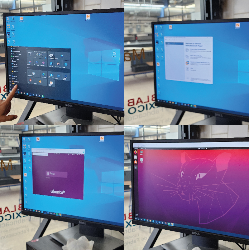
Since the port doesn’t open from Mods in Windows it is important to open a Linux Virtual Machine from VMWare in the computer destined for milling. This is because Linux doesn’t need the drivers to communicate with the machine.
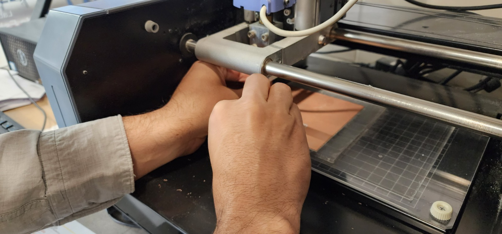
Taking in account there was a already a copper double faced phenolic board set for milling, and some space to mill this PCB, we changed the bit for an angled one, and set the origin parameters. On the second milling attempt the plate was changed by removing the existing one, adding double side tape to the new board and fixing it in the front left corner of the machine (where the first one was)
So first open Mods by openning the command prompt, entering the mods folder by writing ‘cd mods’, and then ‘bash mods’.
Already in Mods right click on the canvas for a blue box to appear and then in order to load the tool chain choose:
- Programs / open program / Roland / MDX mill / PCB
-
Turn on the webSocket pyserial switch and open the socket
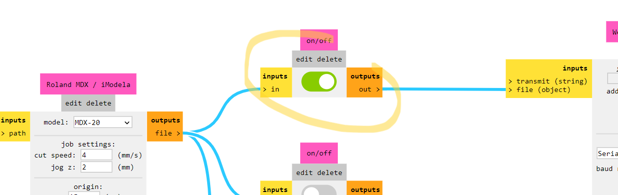
-
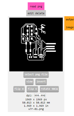
Open the image to mill (first you mill then you cut the perimeter) it is important to note that .svg doesn’t work as well as png
-
Invert the colors so the white is the copper that will remain in the board, or you can already have your image set in this way (even with a high resolution, 1000 dpi, for it to mill properly, I learned this on the second try)
-
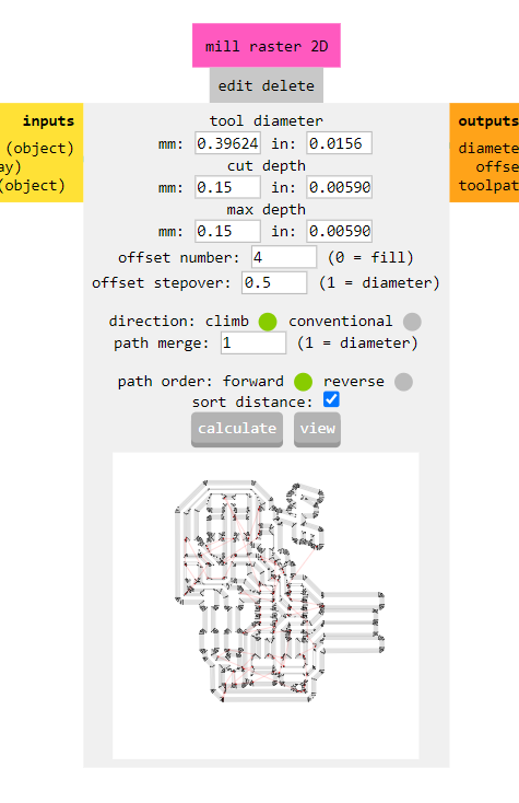
Follow these settings:
- Mill traces offset 4 | Set the mill width to 1/64” (0.3968mm) cut depth 0.10mm and max depth 0.10mm
- Then click calculate to obtain the milling traces and ‘send file’ for milling
The first attempt went off the copper plate, the second attempt (on the right) didn’t come out so good, we found out that on one side the cutting depth was too much (0.15mm) and the resolution for the image was very poor (then we changed to 1000dpi)
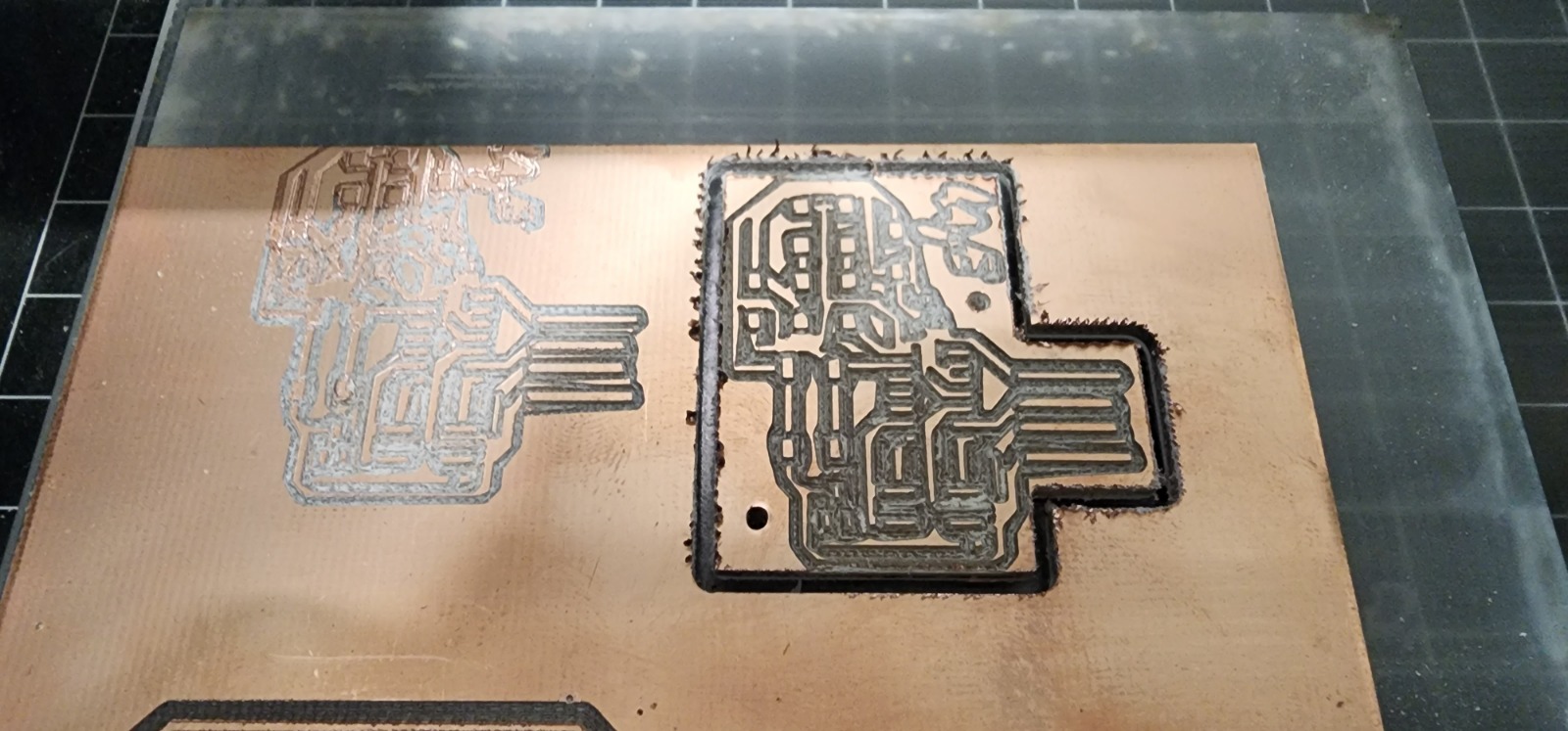
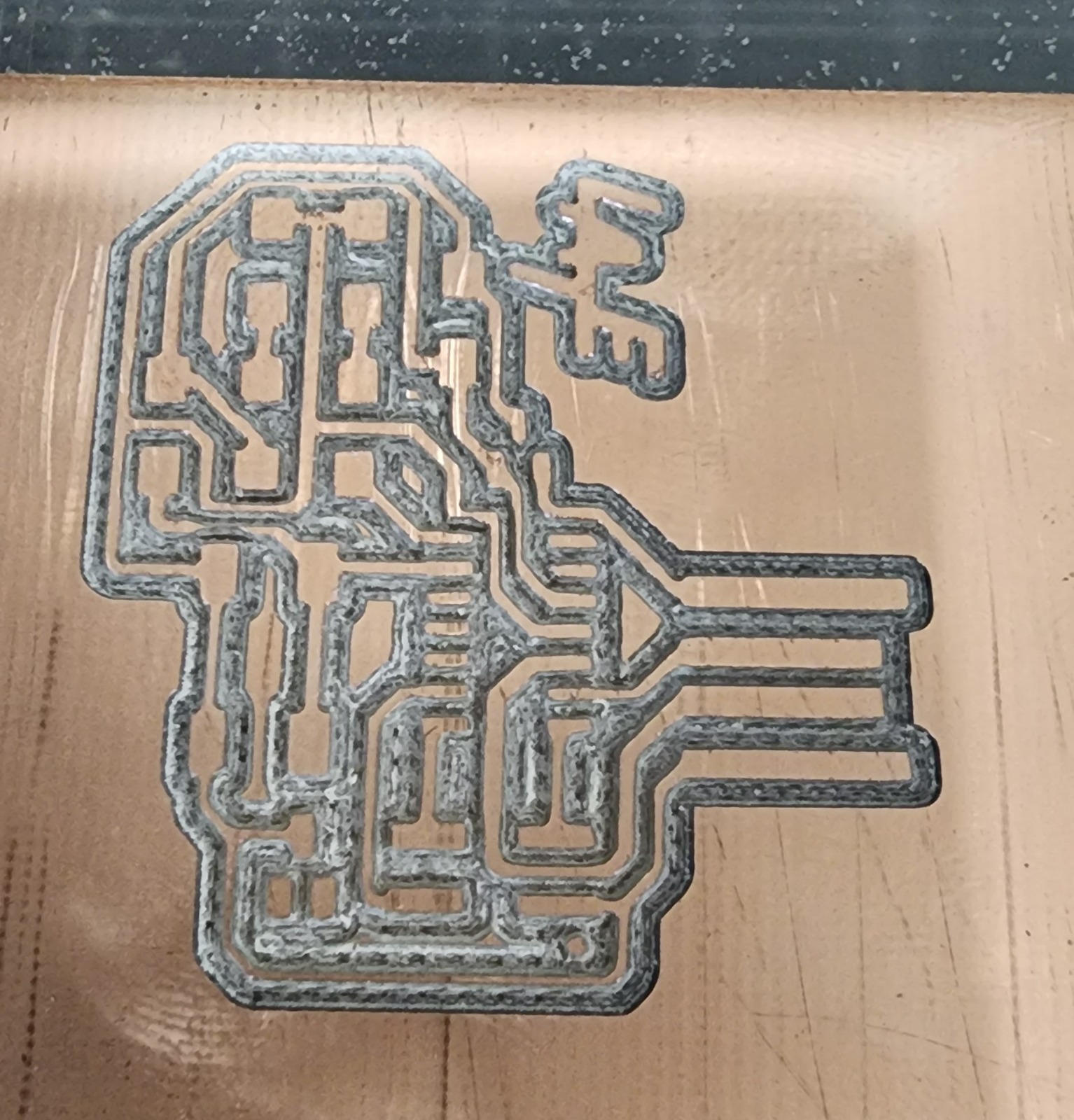
Finally on the third attempt, everything seem working smoothly after fixing depths and resolution.
Soldering
I set some aids for soldering so I would improve my performance since I have sometimes shaky hands.
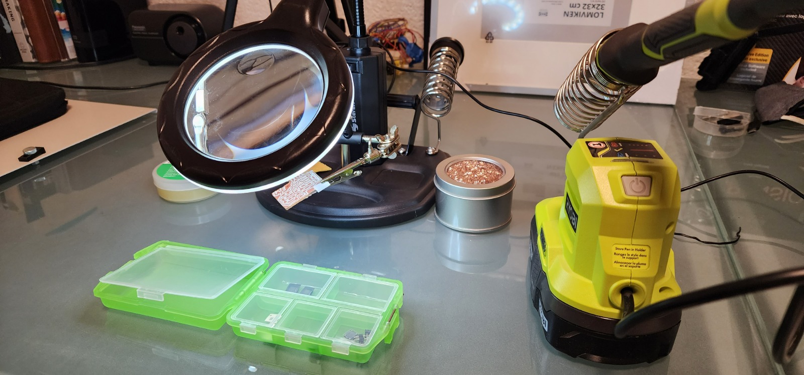
I decided to start from complex to ‘easy’ components and from center to perimeter, so the logical decision was to start soldering the MCU, in my case SAMD11
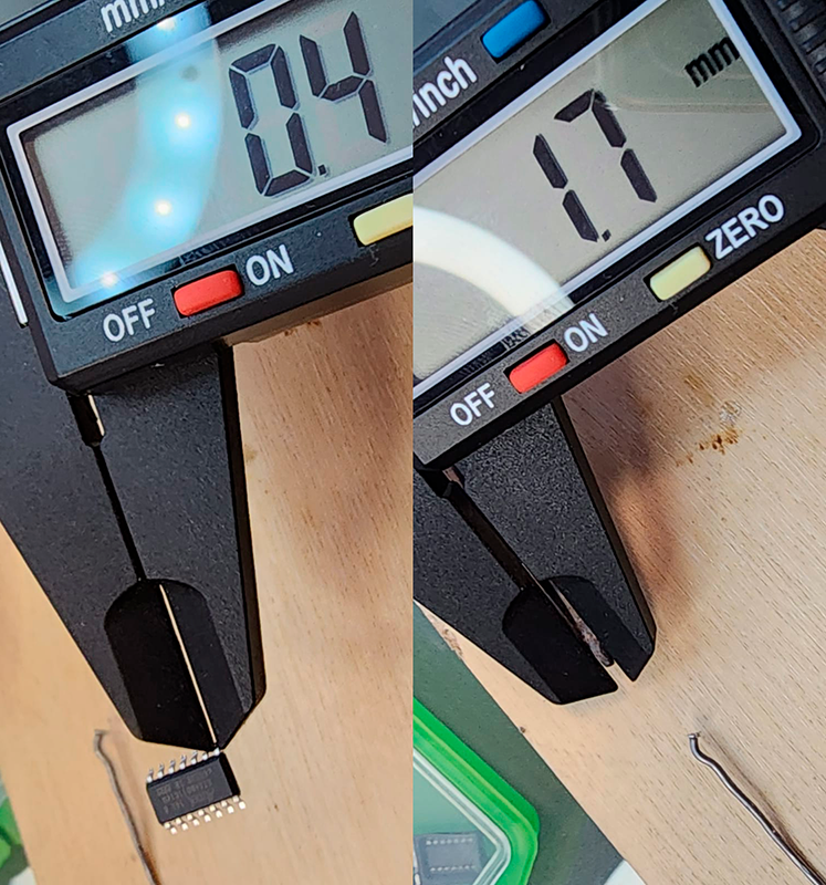
The solder iron and soldering wire (right) exceeded the size of the pins of the MCU (left) so I had to manage to have a better pulse soldering.
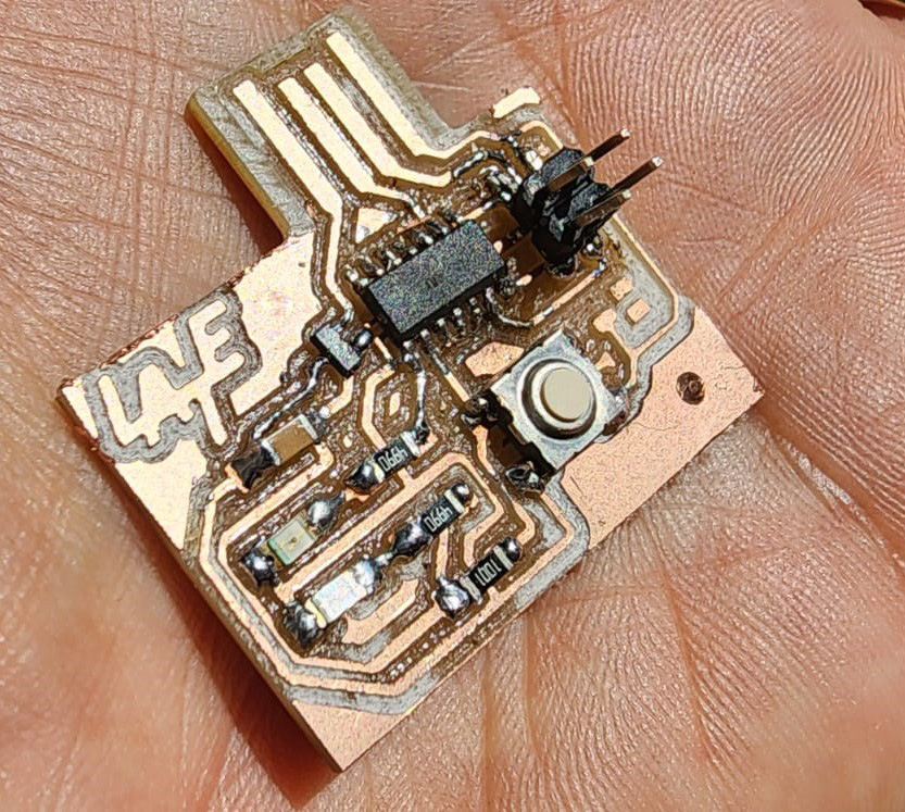
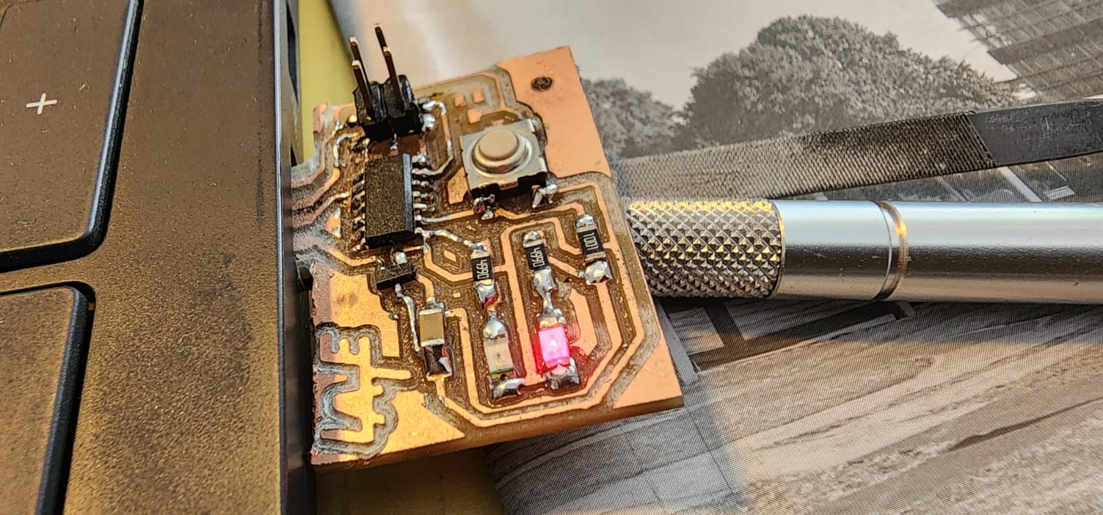
After some lumps, and some hard effort I was able to put together all the parts. I took special attention on the MCU and LED orientation. At the very end I removed some permieter copper from the USB connection.
It seems that it is needed to add a support of about 0.8mm to make proper contact with the USB-A connector
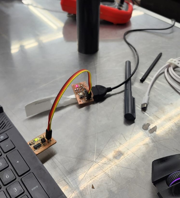
Testing
After having the developer board put together the bootloader had to be loaded into the board.
- In order to do so we need to download the EDBG, in my case I downloaded version 53 from here
- Download the sam_ba_Generic_D11C14A bootloader. You need to have the EDBG downloaded. The bootloader has to be inside the EDBG folder.
- Open terminal. Execute inside the EDBG folder edbg-windows-r53.exe -ebpv -t samd11 -f sam_ba_SAMD11C14A.bin
- Disconnect the Free-Dap programmer from our SAMD11C. Now we connect the SAMD11C to the computer.
- We open the Arduino IDE
- In Preferences, add the URL of the additional cards that you can find here. We need the MattairTech LLC
- The next step is to download Generic SAMD11C in the boards manager.
Then I tried a blinking example.
int relay_1 = 1;
int LED_1 = 3;
char varc = 0;

void setup() {
Serial.begin(9600);
pinMode(relay_1, OUTPUT);
pinMode(LED_1, OUTPUT);
}

void loop() {
while (Serial.available()>0){
  varc = Serial.read ();
  if (varc == 'A'){
    //do something
    digitalWrite(relay_1, HIGH);
    digitalWrite(LED_1, HIGH);
    Serial.print("| off · apagado ");
  }
  else if (varc == 'P'){
    //do something
    digitalWrite(relay_1, LOW);
    digitalWrite(LED_1, LOW);
    Serial.print("| on · prendido ");
  }
}
}