Final Project
Barber/ Salon Chair Vacuum
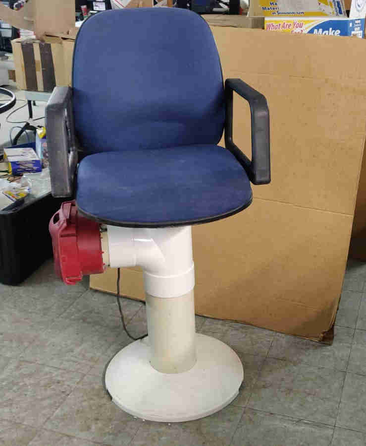
[Hair Waste Vacuum Attachment/ Integrated system for Barbers/ Hair Stylists]

“A device that would be either integrated or attached to a barber’s chair, at its base. This would ease the burden placed on Barber’s/Hair Stylists by decreasing the volume of hair (waste product), that they would have to remove upon completion of their subtractive work. The device can be operated/ controlled via a switch or timer system, which would allow the barber to, always have control of its primary function.”
Note: This is a work in progress, and design variations may change over time.
Final Project Slide

Final Project Video
2D and 3D Modeling
3D Modelling
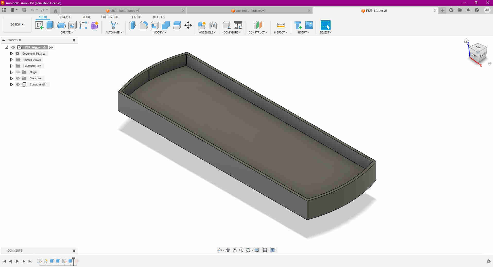
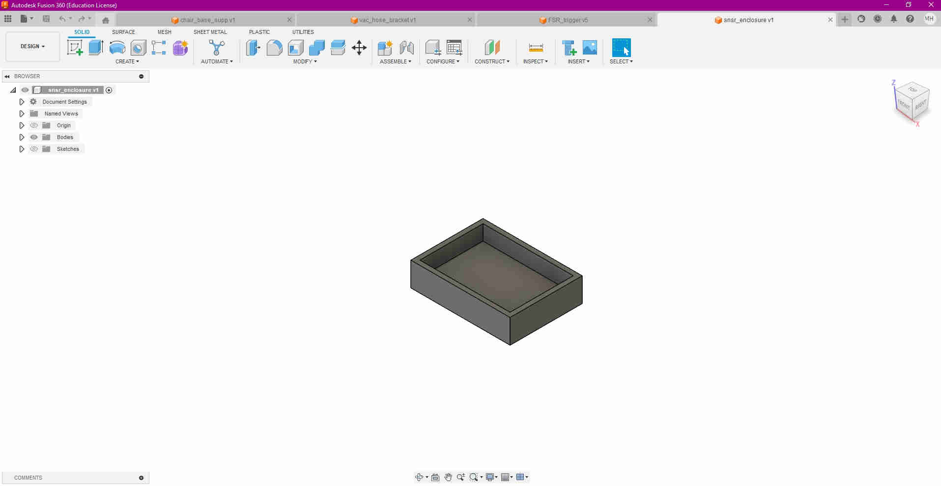
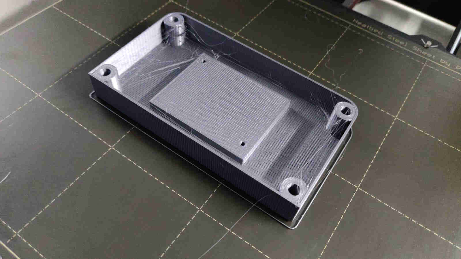
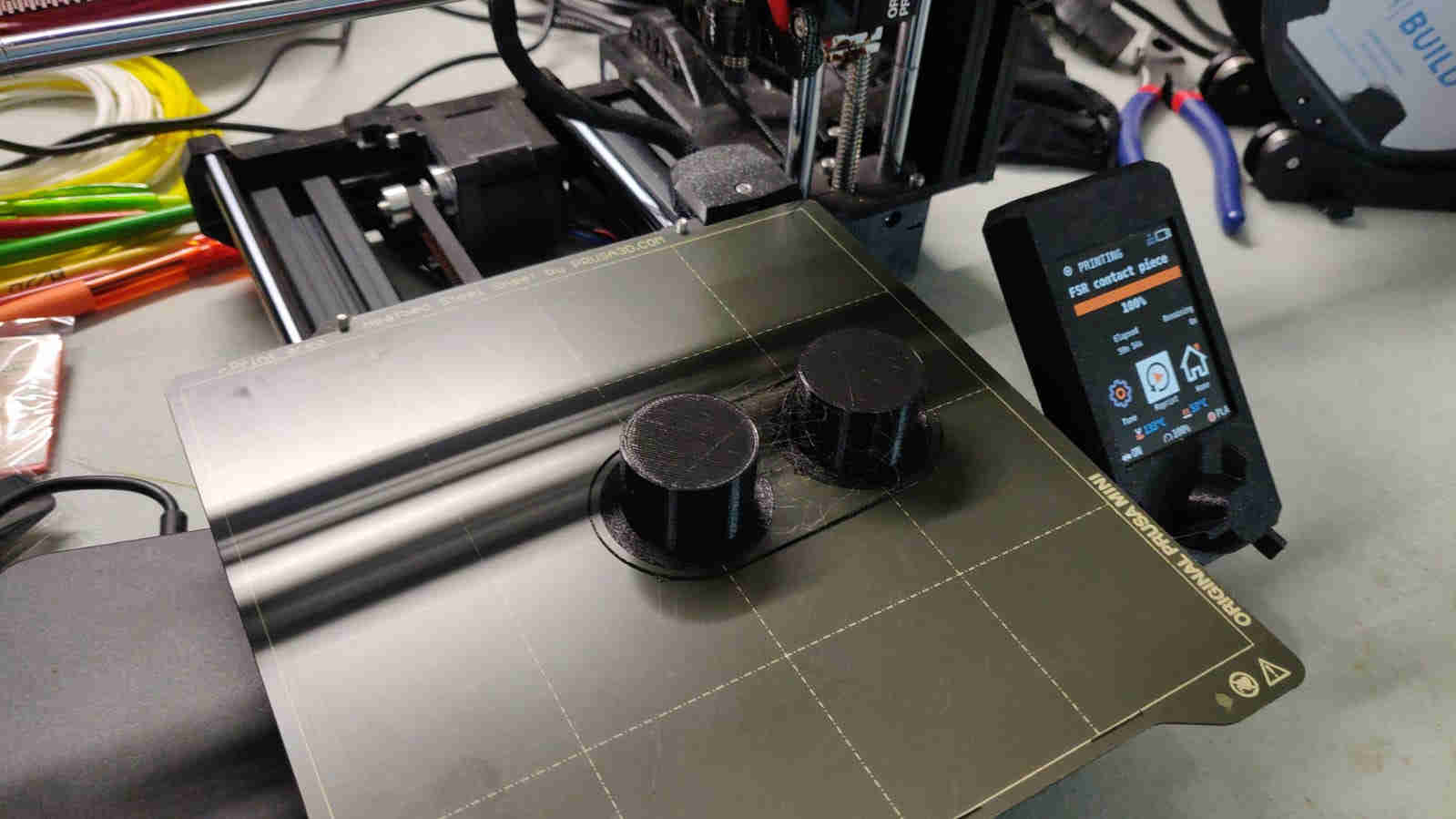
For my final project, there was a quantity of components I needed to design as well as 3D print. As I did before for a number of assignments, I utilised the Prusa i3 MK3S and MK3S+ as well as the Prusa Mini to print the components needed. These components were
In the images below, it is seen that I 3D designed the pieces using Autodesk Fusion 360, and exported the designs as STL files (links above)


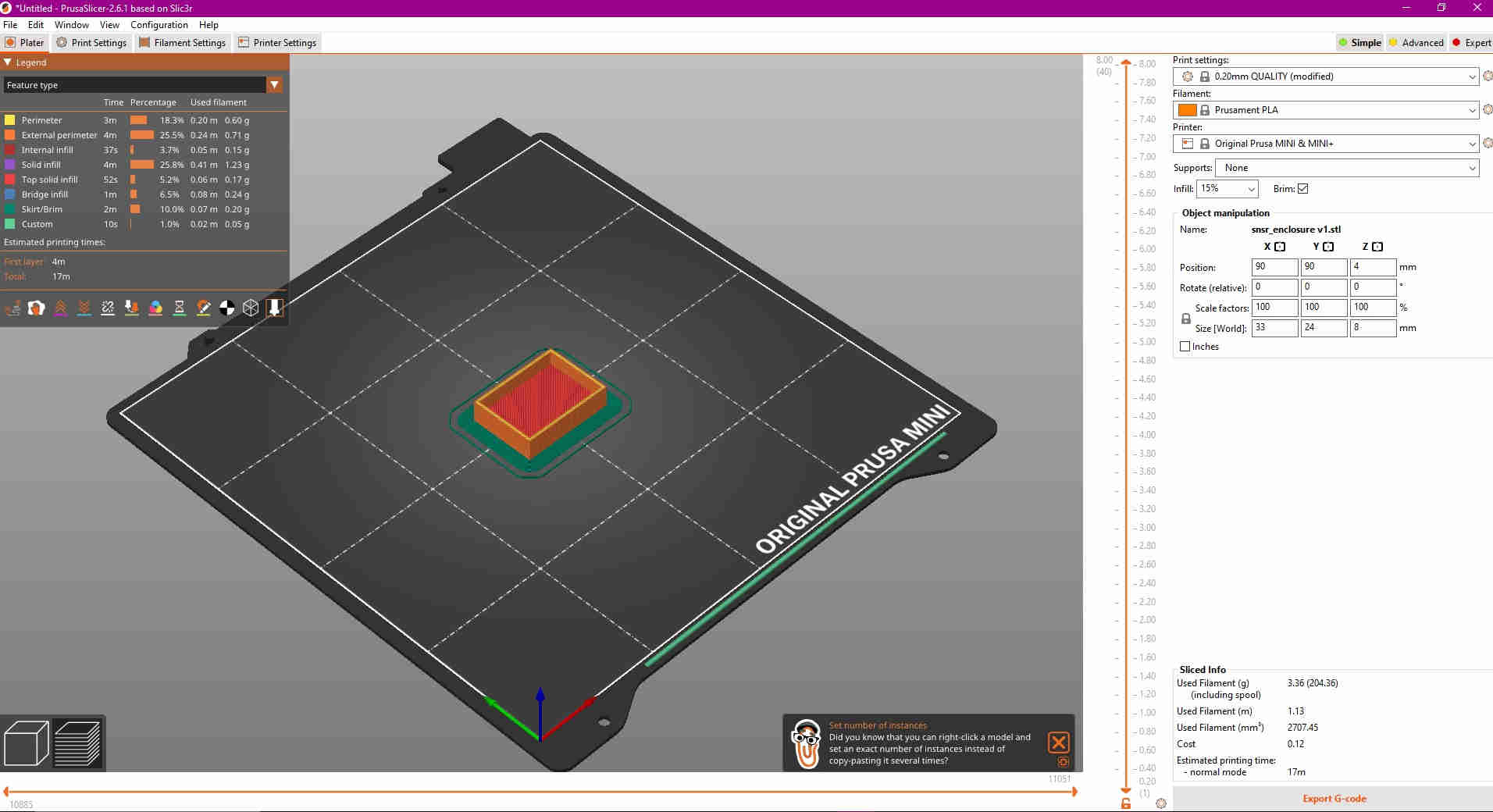
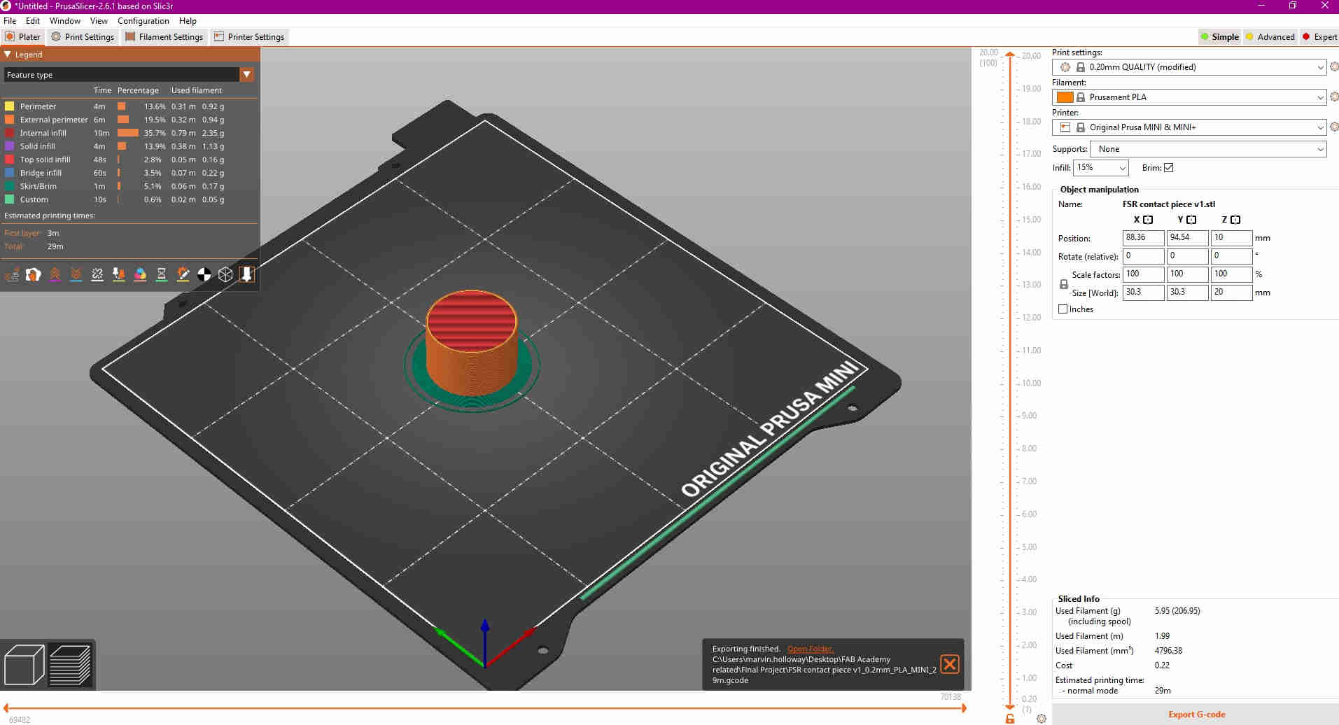
In the Imgaes below, are the design files asthey were prepped to rpint, via the Prusa Slicer


These are the G Code Files used for printing
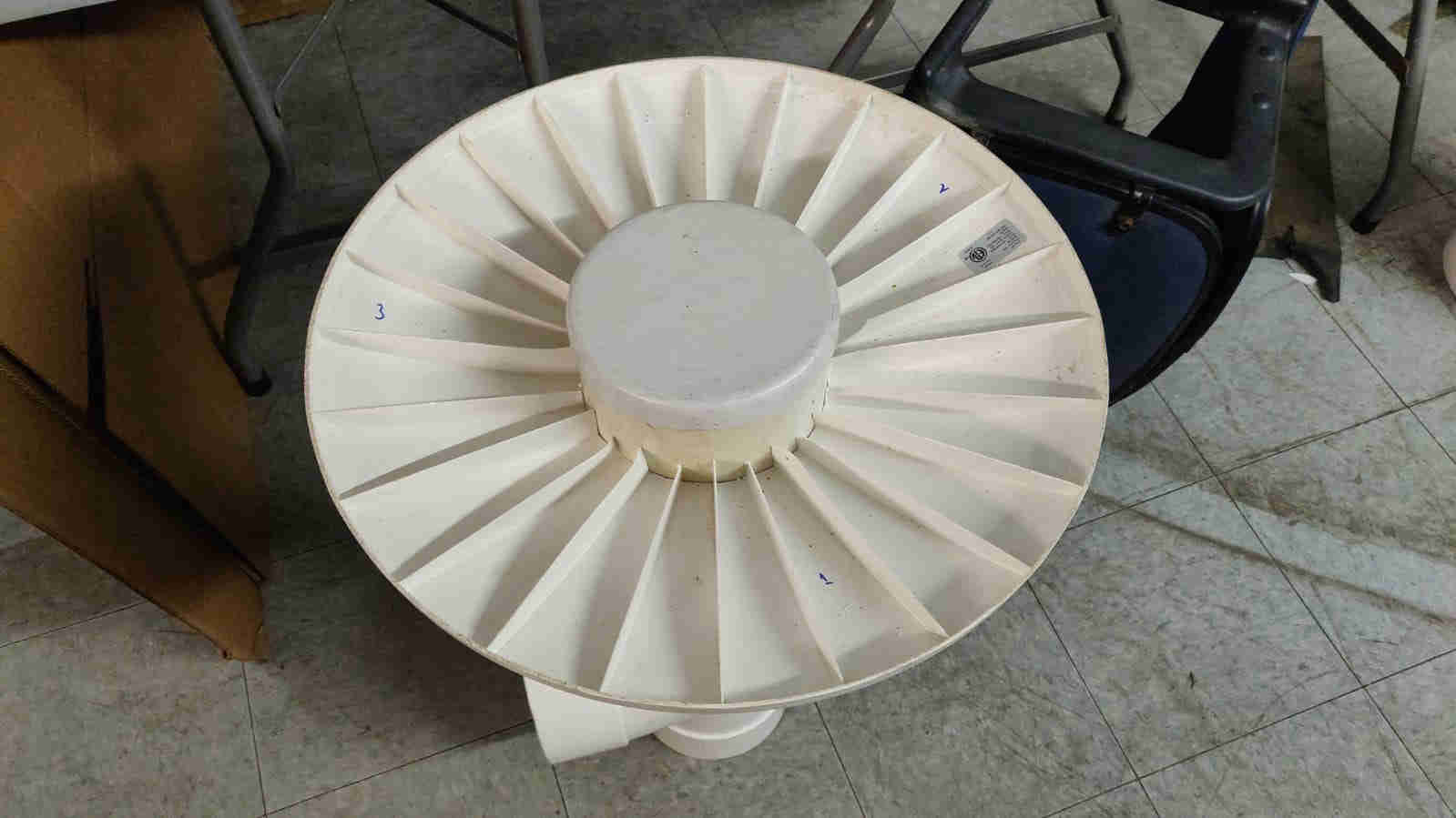
Here are the printed models

2D Modelling
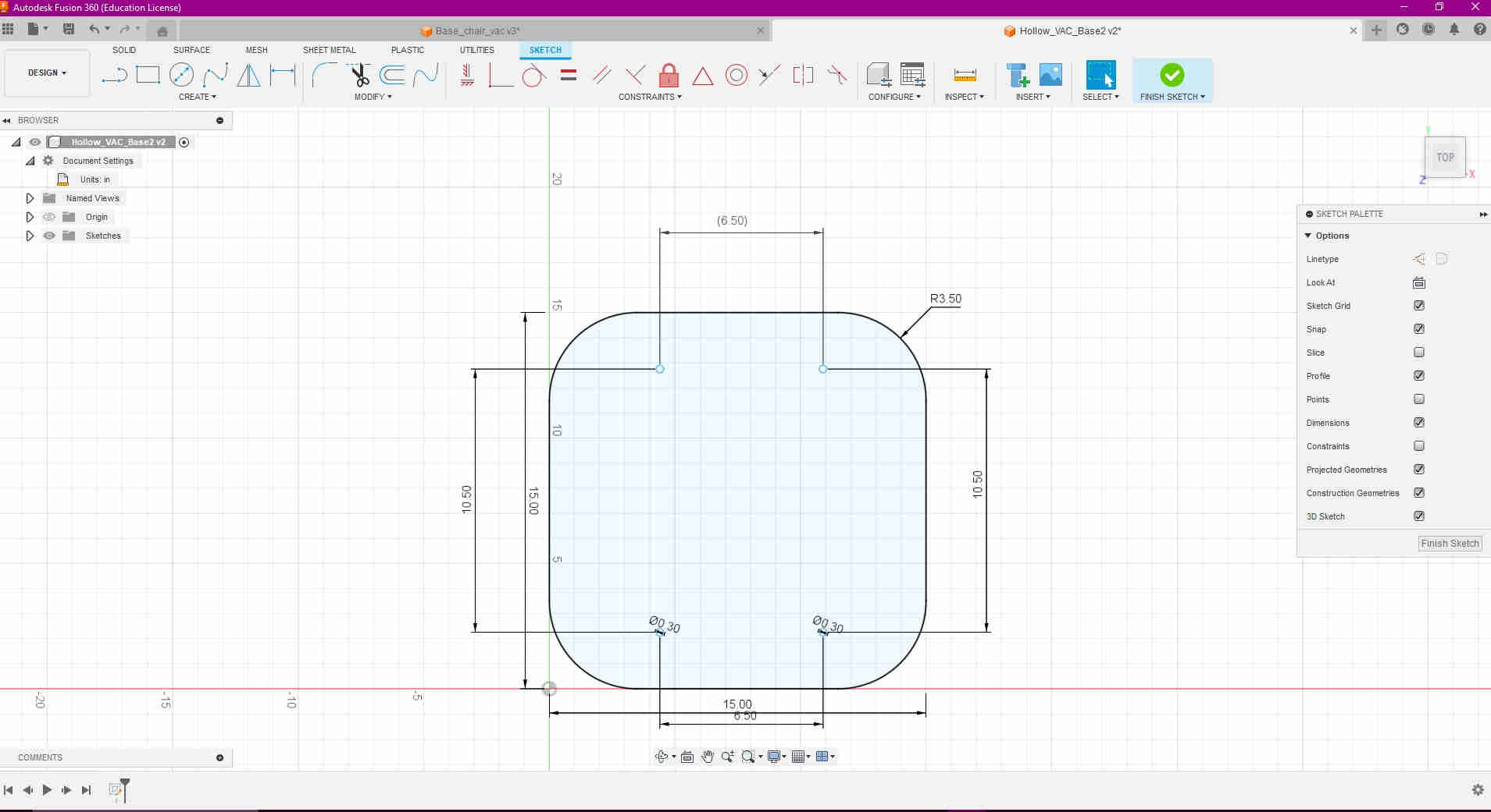
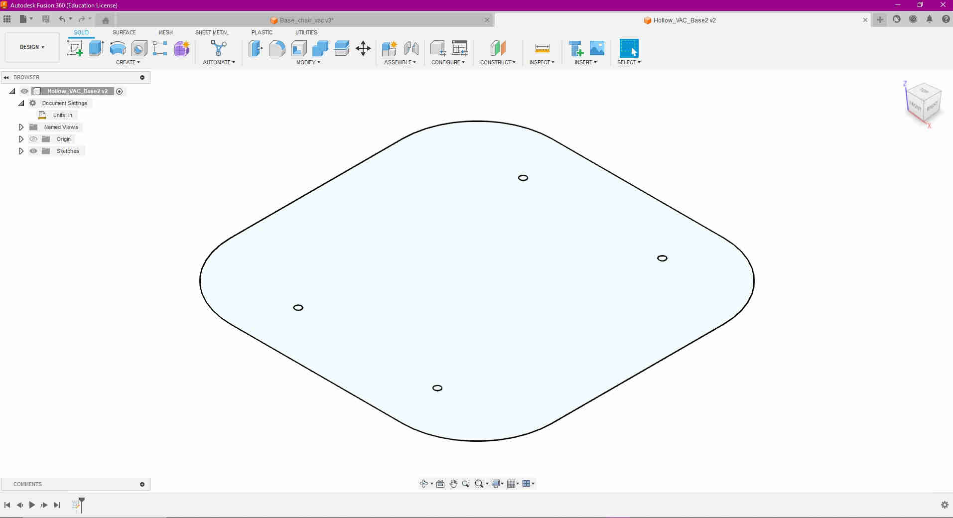
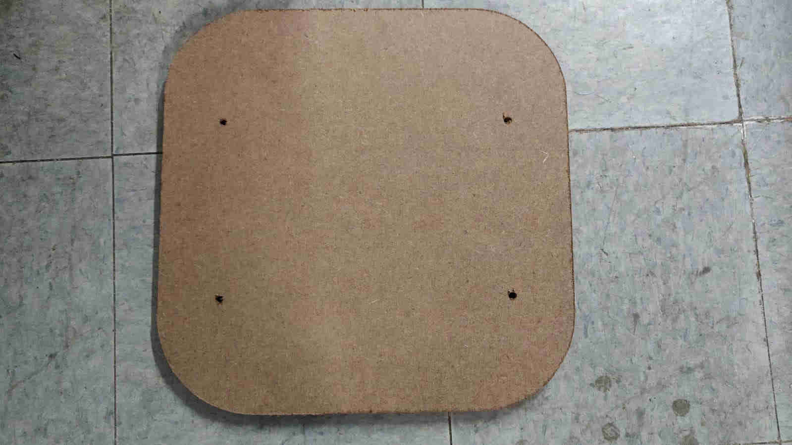
For the 2D Modelling aspect of my Final Project, I decided to design a base piece attachment, using 1/2 inch MDF, that would allow the chair to attach comfortably to the base of the Hollow Vac. As it be the norm, I used Fusion 360 to design a simple yet effective 2D model. To achieve this, I measured off the area of the chairs base, giving specific attention and care to the “screw/ Bolt” orientation and location, as seen in the image below.
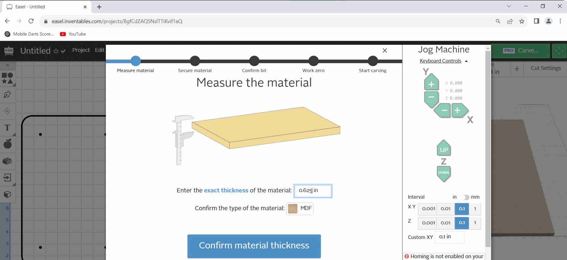
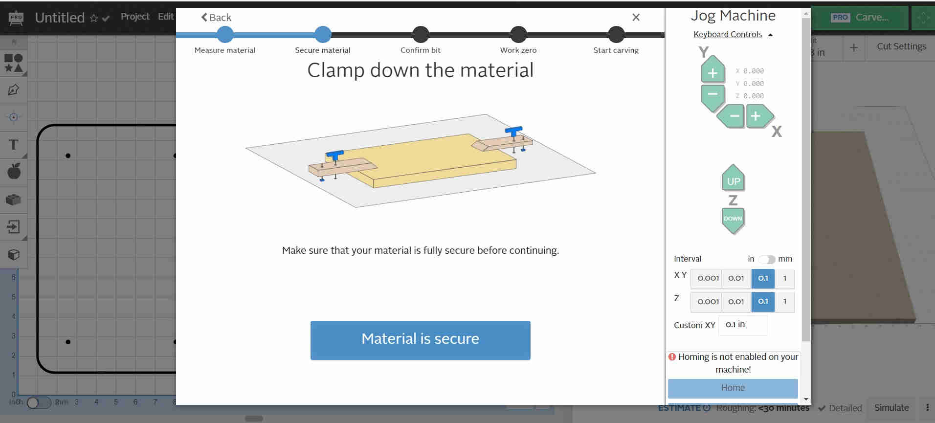
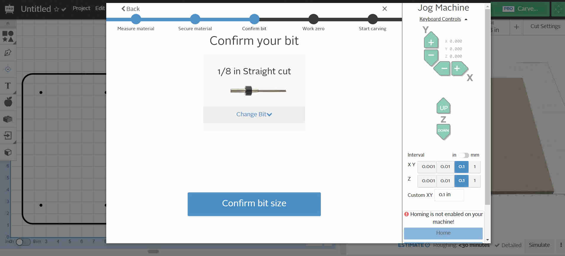
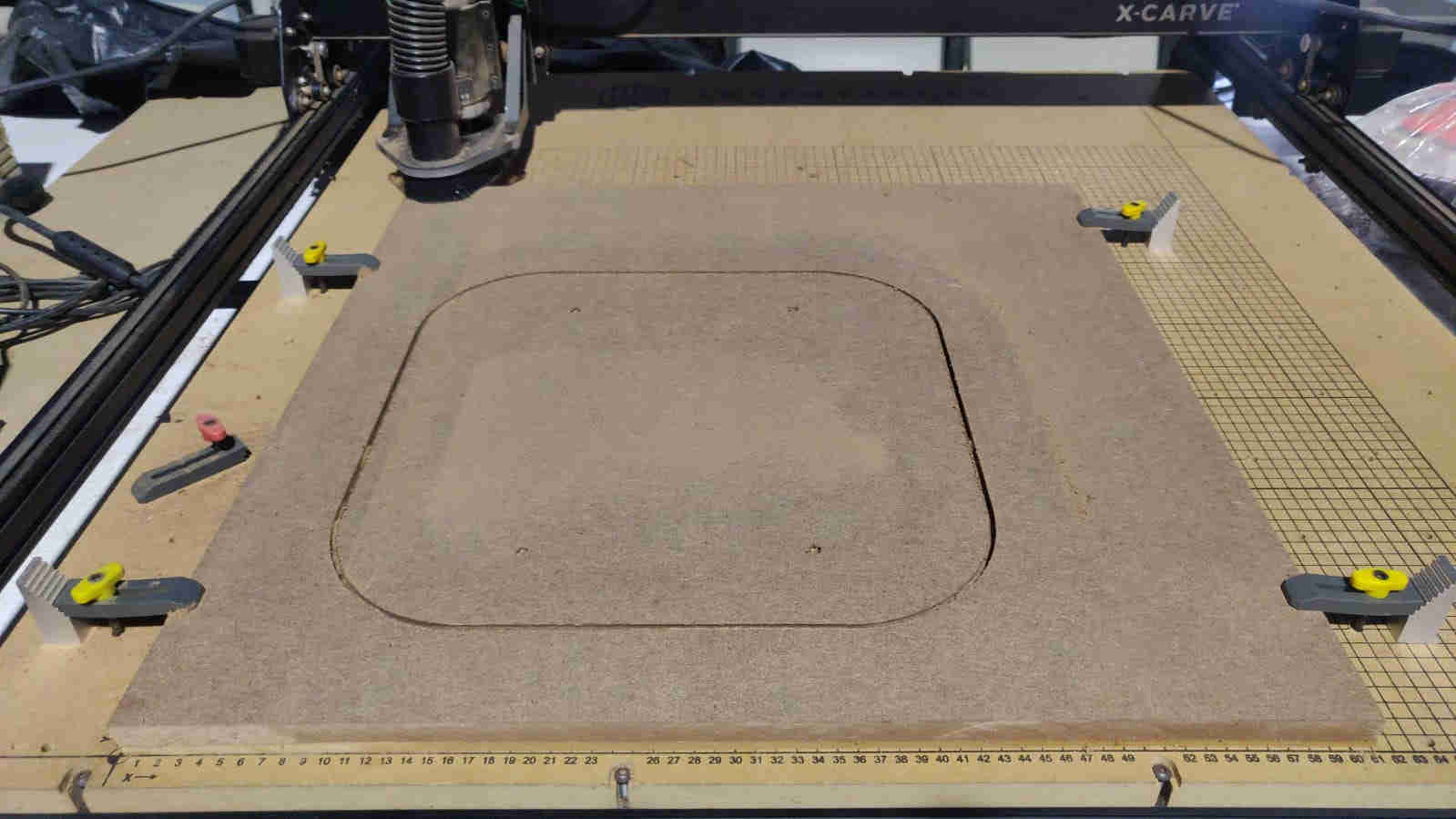
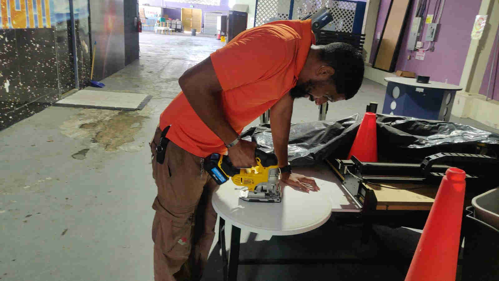
2D Manufacturing
For my next step, I exported my base model file in the dxf format. I then imported said file into the Easel Software. As mentioned within a previous assignment, Easel is an online software that allows the user to edit, operate and manipulate the X Carve CNC Machine (Inventables), with ease. From here, I was able to carve/ cut out my desired design, to the specifications I required, as seen in the videos and images below.
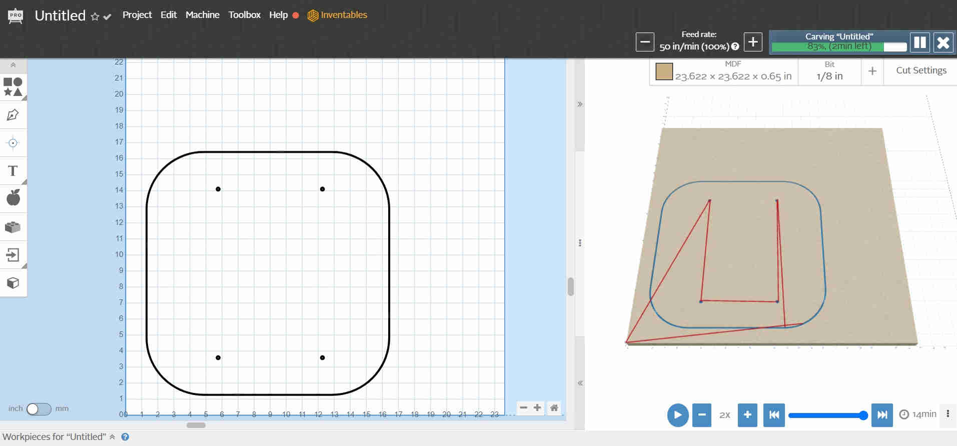
Chair Base Attachment File
PCB Design and Production
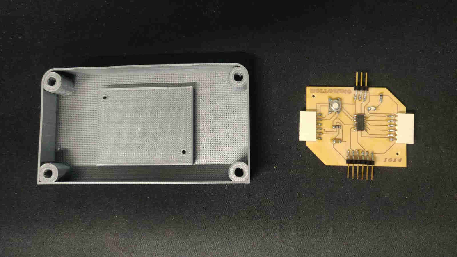
Similarly to my 2D modelling, for the PCB Production and Design, I utilised a previous assignmnet. In that assignment, I mentioned that I would be uting the very same sensor, Force Sensitive Resistor (FSR) sensor, and apply it to my final project process. This PCB design, production and programming process can be found in my Input Devices assignment. Note: A slight adaptation was done to th FSR sensor, to ensure a proper operation of it wihtin the final project. A piece of foam was added to the sensor to ensure an even distribution of pressure.
Component Listing for Hollowino PCB
- ATTiny 1614 Chip x1
- 1uF non polarised capacitor x1
- 1K Ω resistor x2
- Tactile Switch x1
- Bright Blue LED x1
- 3 Pin Conn Header (male) x1
- 6 Pin Conn Header (male) x1
- 6 Pin Conn Header Rcpt (female) x2
PCB Files
Soldering the Hollowino
Materials
| Qty | Description | Price | Link | Notes |
|---|---|---|---|---|
| 2 | PVC 7 ” End Cap | $100.00TTD | Local Hardware | $50 each |
| 1 | PVC 7 ” Pipe | $0.00 | Recycled | |
| 2 | 1 k ohm Resistor | $0.10 | https://www.digikey.com/ | Ordered many |
| 1 | Keystudio FSR Sensor | $5.10 USD | https://www.keyestudio.com/keyestudio-thin-film-pressure-sensor-for-arduino-p0125.html | Ordered as part of an Arduino Kit |
| 1 | ==ShopVAC== | $0.00 | Old vacuum head Repaired and repurposed | |
| 1 | Lasko Fan Base | $0.00 | Recycled/ repurposed | |
| 2 | Conn 6 FTDI smd Header | $0.54 USD | https://www.digikey.com/ | Each rail costs $3.45 USD |
| 1 | LED BLUE CLEAR CHIP SMD | $0.28 USD | https://www.digikey.com/ | per tape, ordered many |
| 1 | Non polarised capacitor 1 Microfarad | $0.05 USD | https://www.digikey.com/ | Ordered many |
| 1 | Single side copper laminate PCB Board 7cm x 10cm | $0.45 USD | http://amazon.com/ | |
| 1 | Various nuts and bolts | $0.00 | Reused from old STEM Kits | |
| 1 | Acrylic Plastic (Plexiglass) 1/8” | $550.00 | Local Hardware | per sheet, but a small piece was used |
| 1 | ATTiny 1614 MicroChip | $0.90 USD | https://www.digikey.com/ | |
| 1 | Sheet 1/2 ” MDF Board | $150.00 | Local Hardware | of a sheet, a small piece was used |
| 1 | Roll 3d Filament | $11.50 USD | https://www.matterhackers.com/store/c/3d-printer-filament | |
| 1 | Vacuum Hose 2” Diamter | $0.00 | Recycled | |
| 1 | 3 Way Charlotte Joint (T-Joint) 7 ” PVC Fitting | $0.00 | Recycled | |
| 3 | 1x25 Metal Steel Bar | $0.00 | Reycled from old VEX Robotics Kit |
Assembly
The overall assembly process was taking in 3 stages.
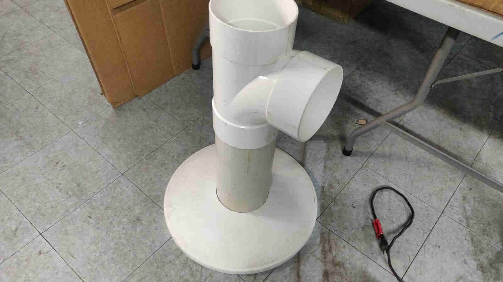
Stage 1
At this stage, the vacuum base was fitted together. All neccessary components were placed as intended and once complete, tested. The images/ video below shows this process


Stage 2
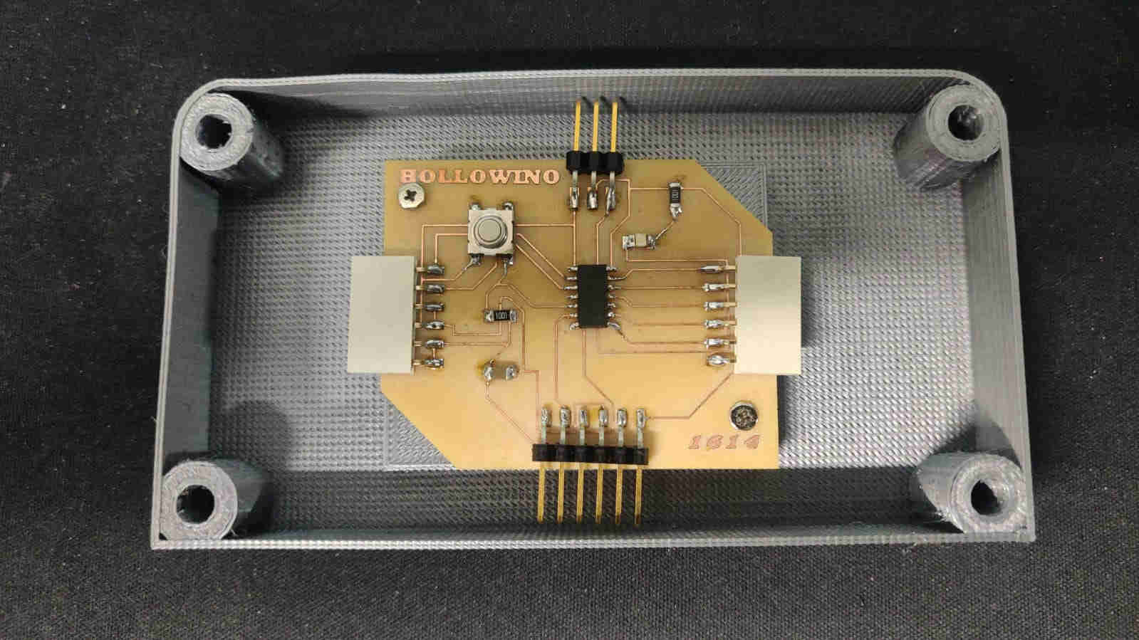
Stage 2 takes me through the process of assembling and retrofitting the PCB as well as the FSR sensor/ trigger with thier respective enclosures to the base. The images below illustrate this.


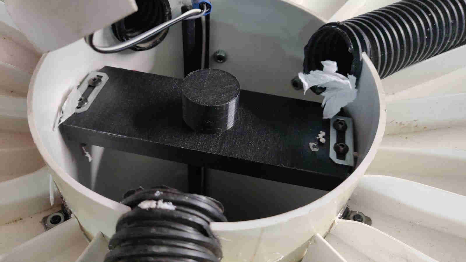
Stage 3
This stage, quite possibly entailed the least complex part of the assembly, fitting the chair piece to the vacuum base.
Testing/ Operation
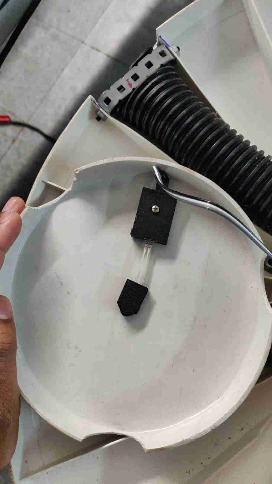
The testing phase took two operations into consideration, testing the sensor with the trigger mechanism as well as the main function which was that of the vacuum system. Ideally, for the trigger system to work, it is soley dependant on the 3D printed piece accumulating weight via the debris (hair), caught in the vacuum over time. Once the trigger exceeds its weight threshold, it places pressure upon the FSR, which in turn sends a signal to the LED in the PCB, which is in an “ON” position by default, to turn completely off. The videos below shows a “Successful” operation of the HollowVac.
FSR Test
Vacuum Test
Trigger Mechanism Movement Test