5. 3D Scanning and Printing
This week I worked on 3D printing and scanning assignment. For this week we were to:
Group assignment: - test the design rules for your 3D printer(s) Individual assignment: - design and 3D print an object (small, few cm3, limited by printer time) that could not be made subtractively - 3D scan an object (and optionally print it)
Group Assignment
Here is the link for the Group Assigment. - 3D Printer
3D Design
For my 3D prinintg assignment, I opted to utilise the Fusion 360 App to bring my design to fruition. One of the criteria for this assignment was tot create an object that can be printed using the additive procees, but cannot be easily replicated using the subtractive process. At first, I decided to design something relatively simple, a hexagonal plate, similar to a honeycomb, that had a tiny hook within it. The purpose was to create 9 of these that attached together like a honey comb, and use them as mutiple key racks.
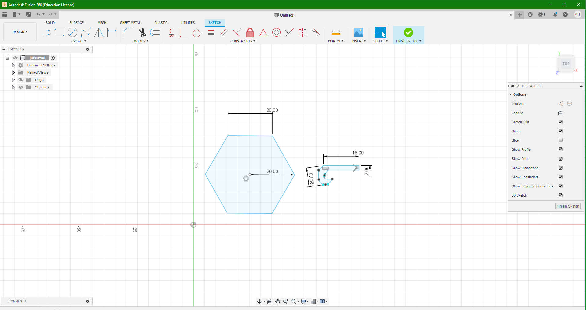
- A quick Sketch of the Key Hook
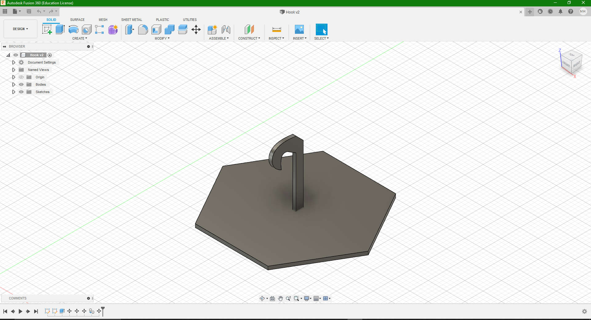
- My sketch of my Hook design 3D rendered and assembled
However, upon close completion of this, I soon realised that this did not fit the required criteria, and could easily be done using the subtractive process. Subtractive processes involve removing material from a solid block of starting material. Machining, milling, and boring are all subtractive processes that create or modify shapes. In an Additive process an object is created by laying down successive layers of material until the object is created. At this point I had to redesign my idea. For this I decided to design a simple “Toy Top”.
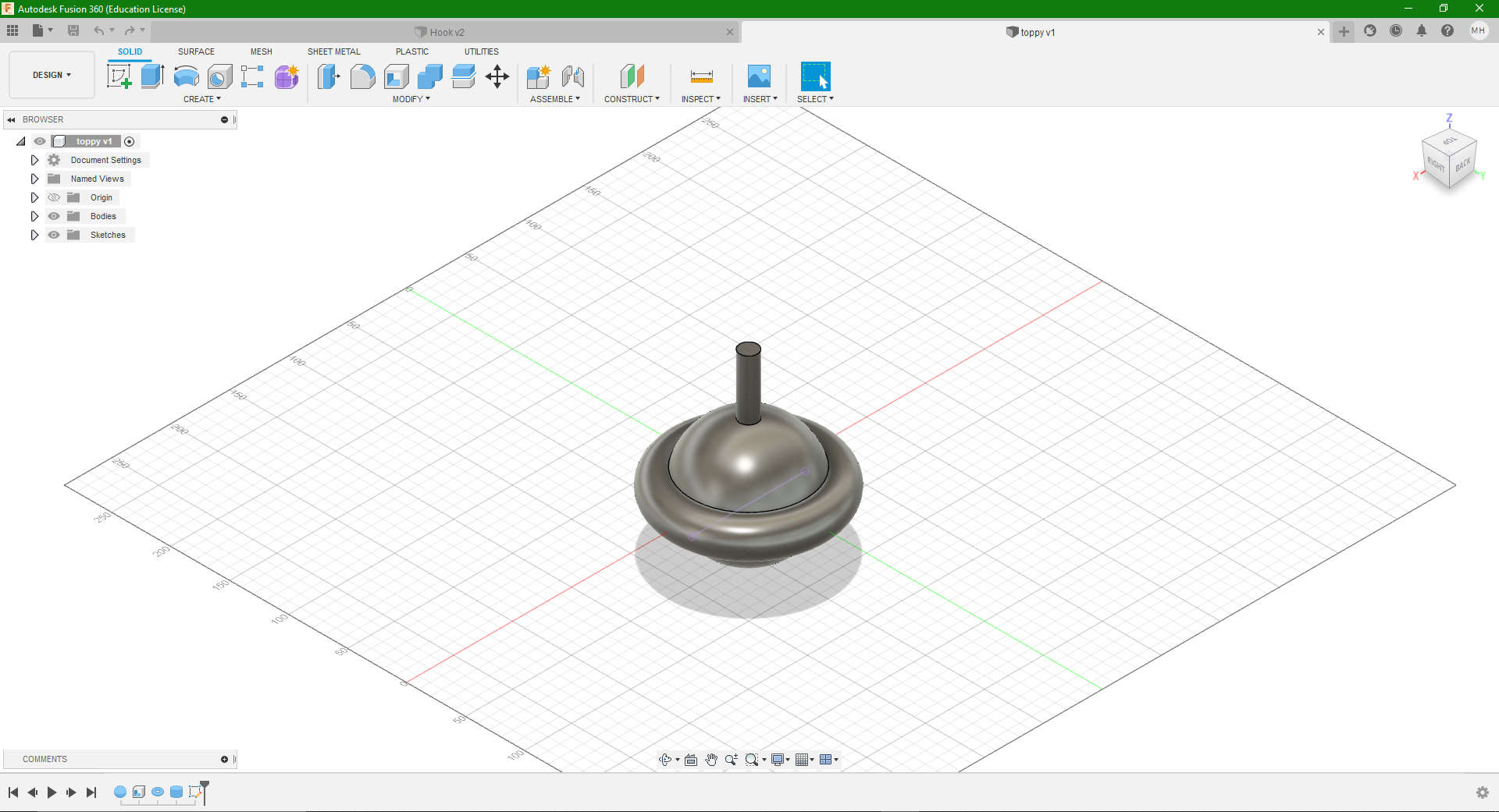
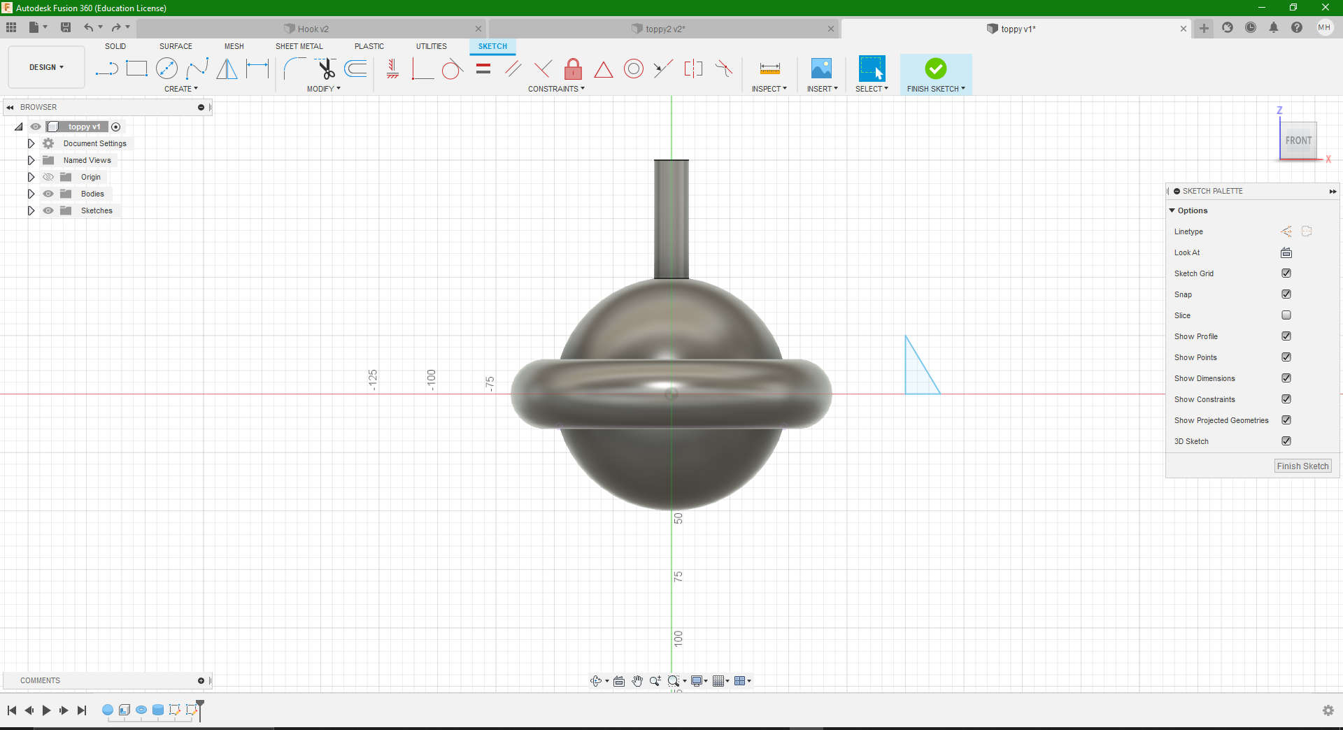
- This is the unfinished Top, it’s essentially a combination of a sphere, cyclinder, cone and a torus. As you can see it ‘s missing the signature point (pardon the pun), of which it uses to balance on while spinning.
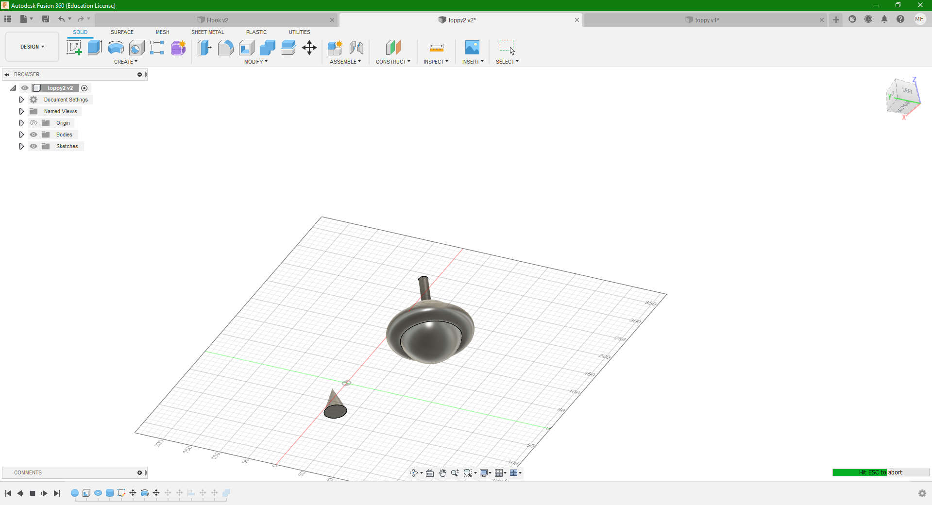
- To achieve this, a simple right angle triangle was sketched, and the (Revolve) function was used to create that conical shape.
- This the 3D rendered view with the cone
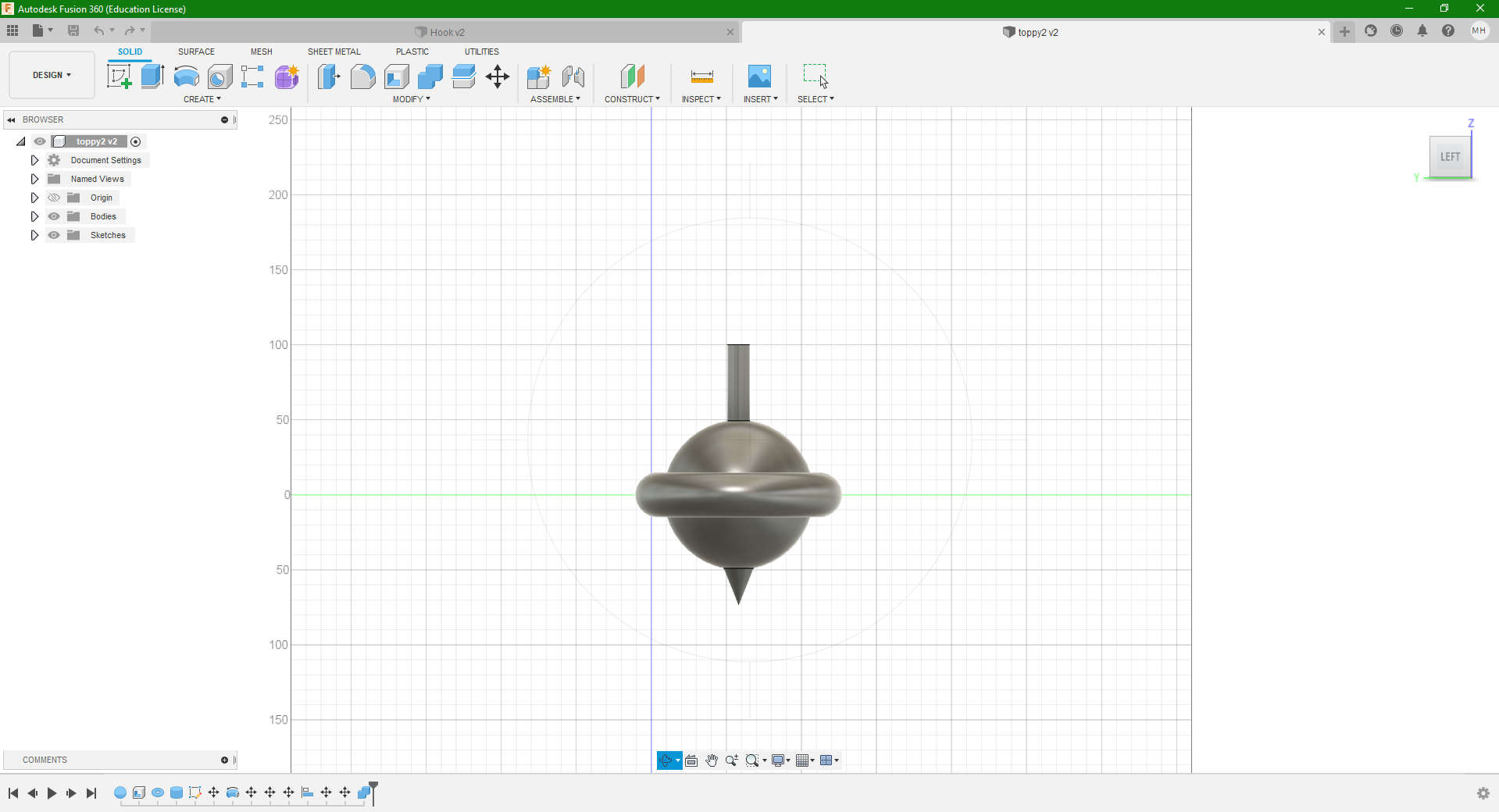
- After this, the point was aligned and assembled/ combined to the rest of the top.
3D Printing
At our FABLAB, we have a range of different brands of 3D printers, from a Makerbot to a FlashForge. For this assignment, I decided to utilise the Flashforge Creator Pro 3D printer. Why you may ask? One simple reason is that the Flashforge’s Replicator G Software is easier to manipulate than that of the Makerbot, also worth mentioning is that the Makerbot Replicator we have in our posession is a bit outdated.
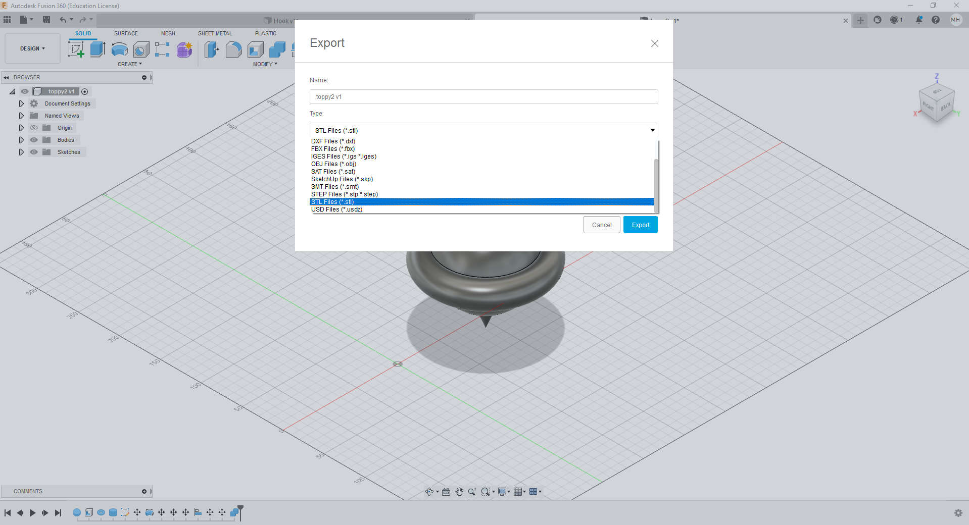
- To prepare my design for printing I first had to export my file into an .stl format for the machine to recognise the print.
- Once this was done, I proceeded to open my design within Flashforge using the Replicator G software.
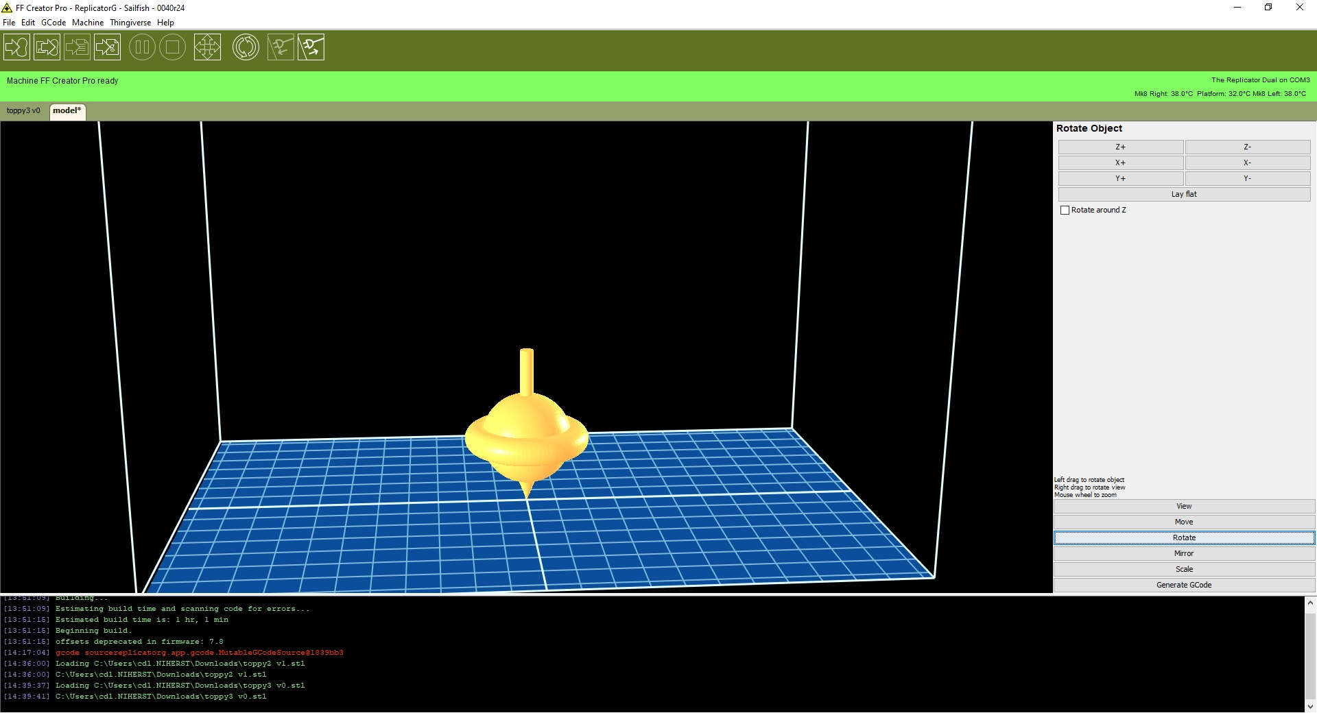
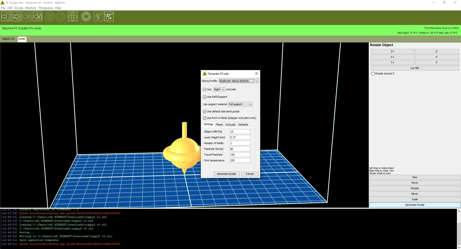
- As I was satisfied with the scale and positioning of my design as well as material of choice, which in this case was white PLA, I proceeded to generate the GCode, ensuring that full support was selected, with 15% infill
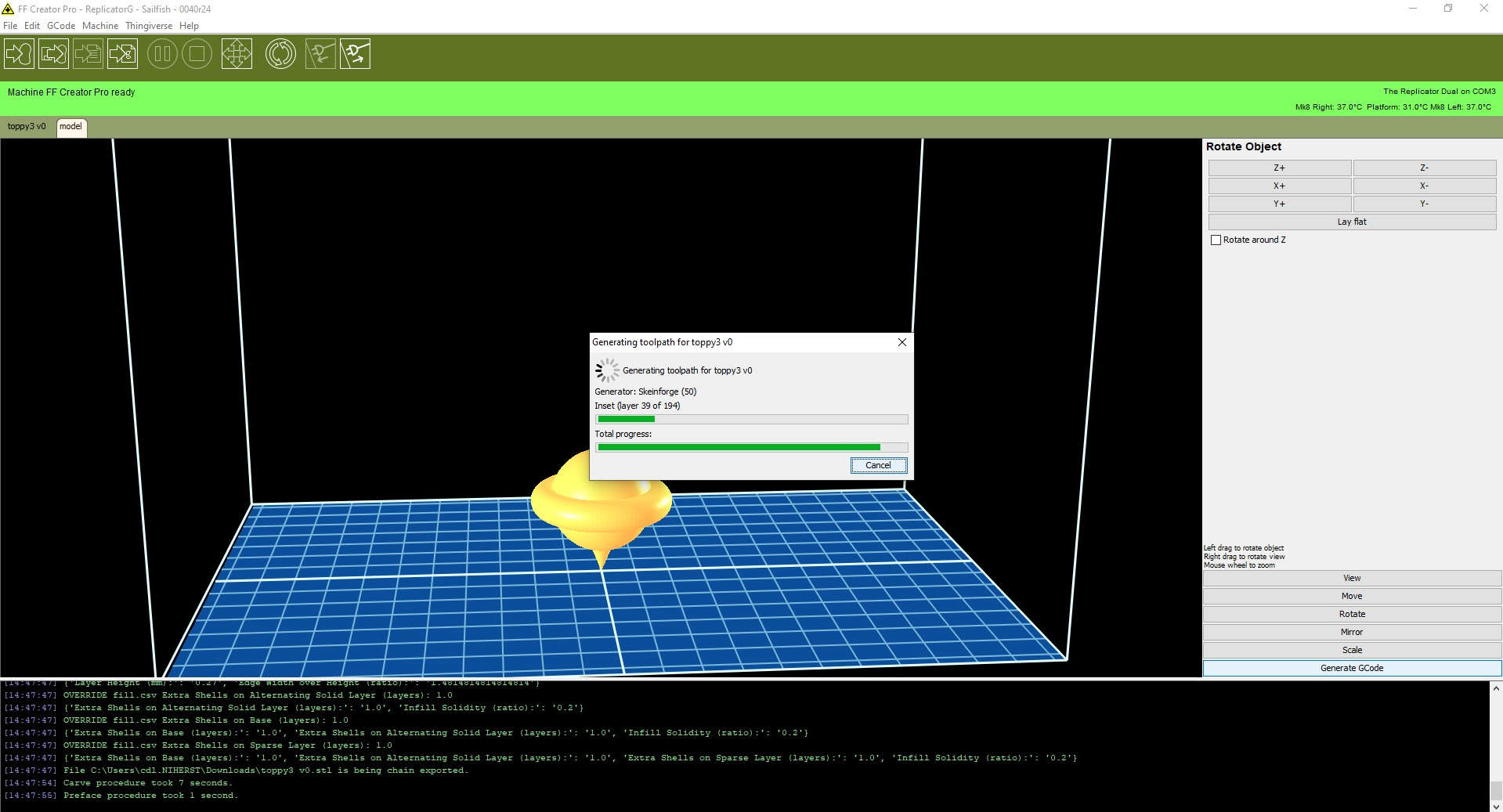
- Thus began the procedure fo generating the toolpath and GCode for the print
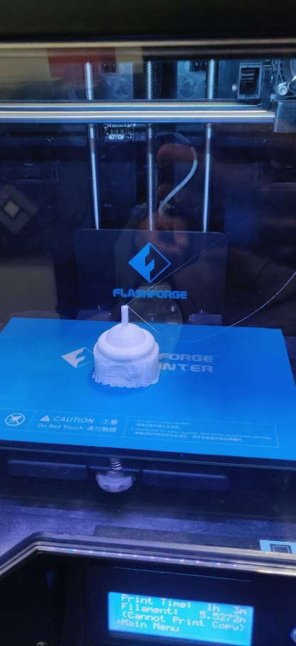
- With this complete, the machine estimated approxmately 51 minutes and 18 seconds for the job to finish.
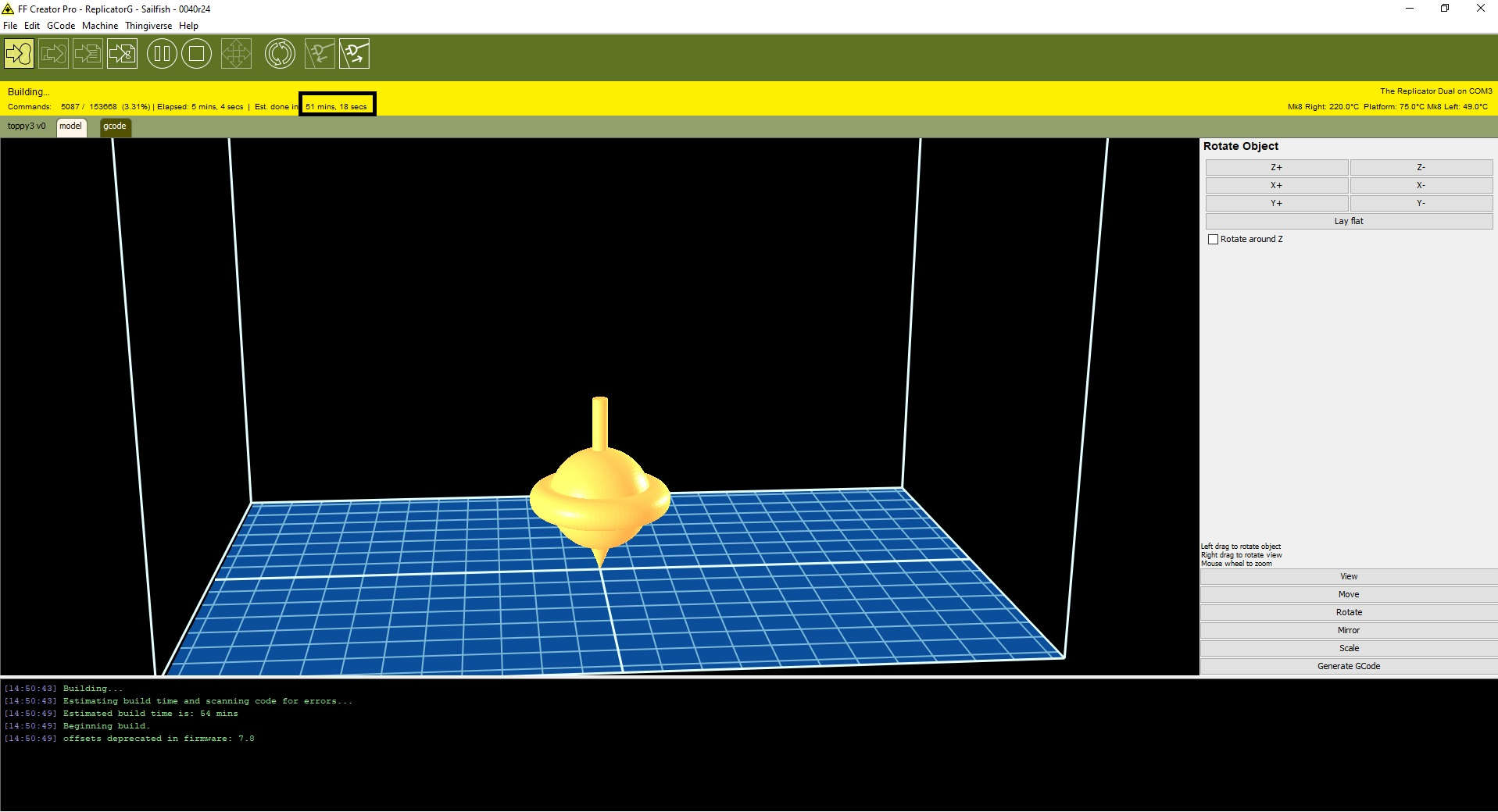
- In actuality, the Print took 1 hour and 7 minutes to complete, this was most likely due to catering for heating of the extruder and positioning.
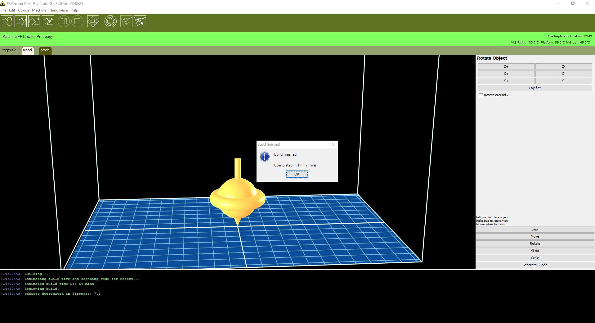
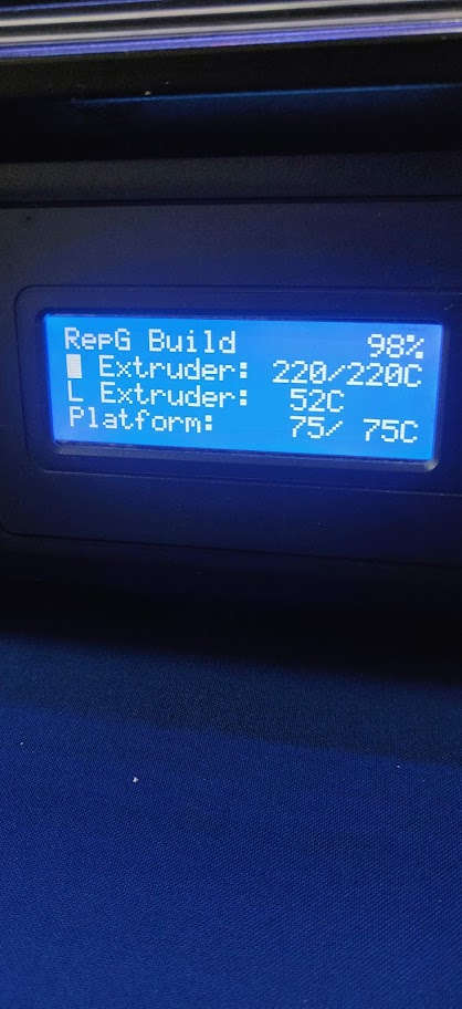
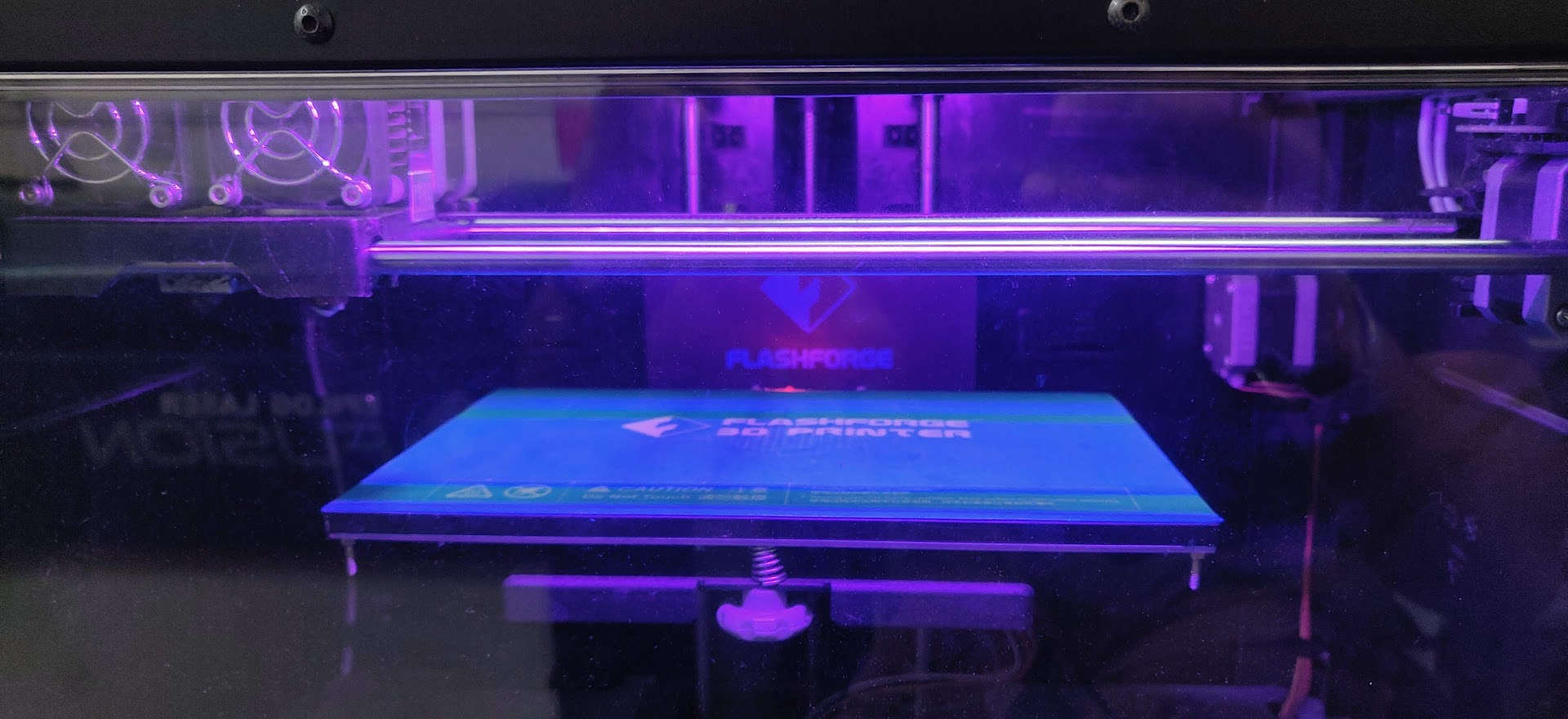
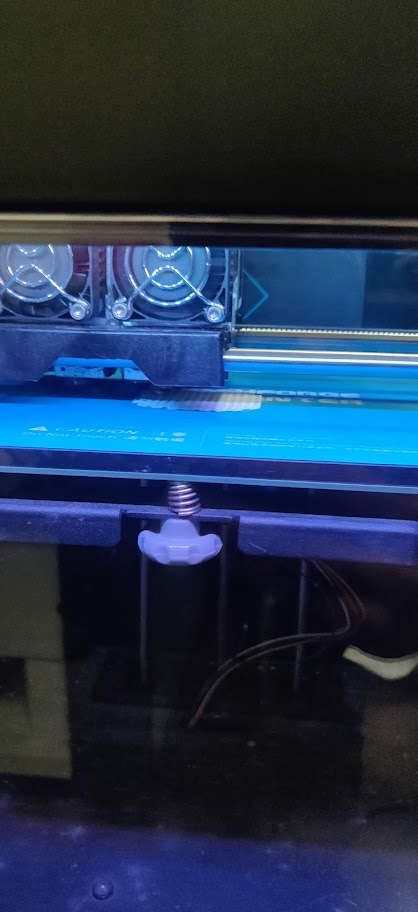
Below are some images depicting the printing process. Take note of the heating temperature as well as the support material used to stabilise and ensure a solid symetrical build.

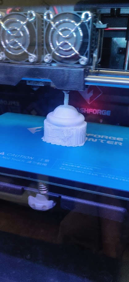
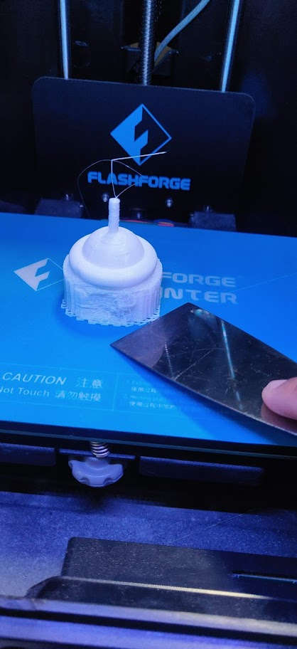
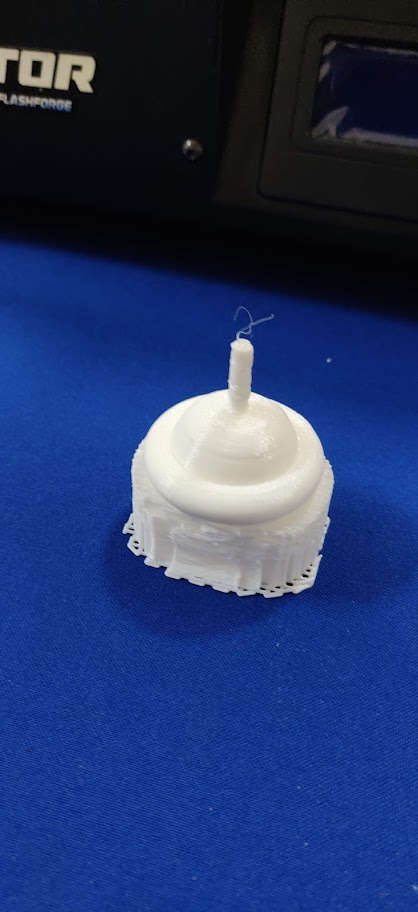
It should be noted that removing the support material was a bit challenging. I used a rework station as well as a dremmel rotatry tool to remove excess material. Note to self, a rework station requires some experience and skill not to burn one’s self!
3D Design File found here Toppy
Useful Apps
3D Scanning
Coming Soon! Once we sort out the software issue with our 3D scanner, Next Engine Scan Studio.
Update!
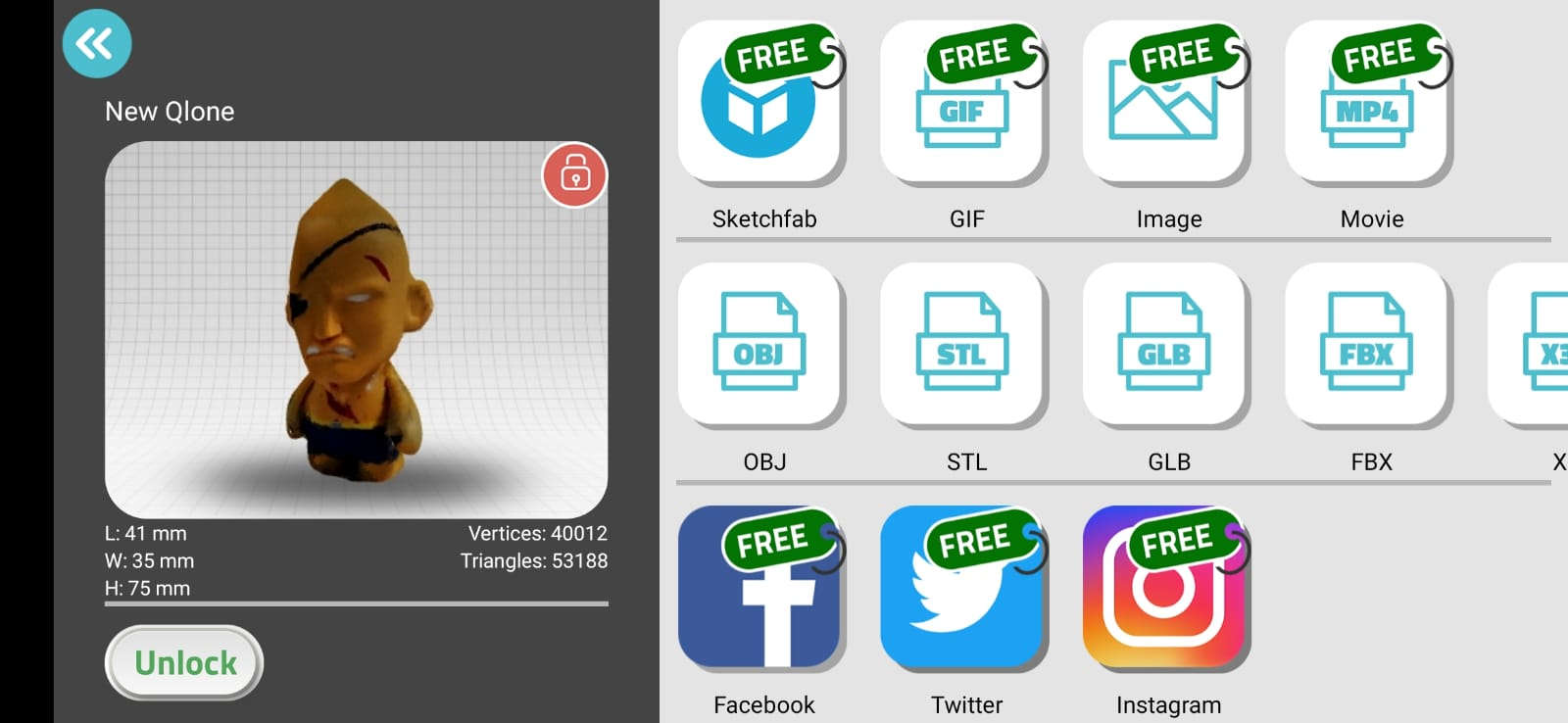
Unfortunately, I was unsuccesful in getting the 3D Scanner we have in house (3D Next Engine Scanner) to work, primarily because of an account issue. However, I decided to utilise on of the other options listed. For my 3D Scan, I used the Android app [QLONE]. This app uses the process of photogrammetry. Photogrammetry literally means the act of deriving precise measurements from photographs. It involves taking a set of overlapping photos of an object, building, person, or environment, and converting them into a 3D model using a number of computer algorithms.
Only the Trial version was available at the time with a 3 Hour Trial window in which to use it. No worries, it was pretty straight forward to use the app
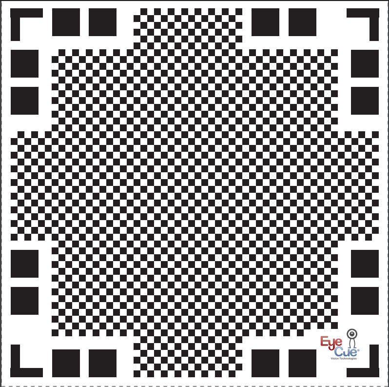
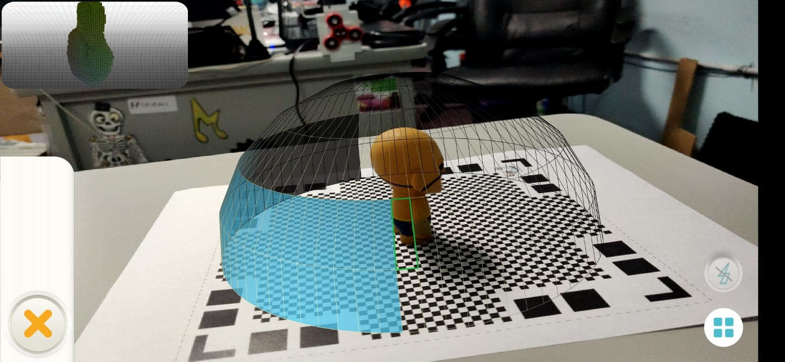
First, I had to print out the QLone mat provided. This mat serves as a tool to more accurately scan the 3D object to be rendered, as it has a QR code, or quick response code that generates a dome type Augmented Reality image when used within the app.
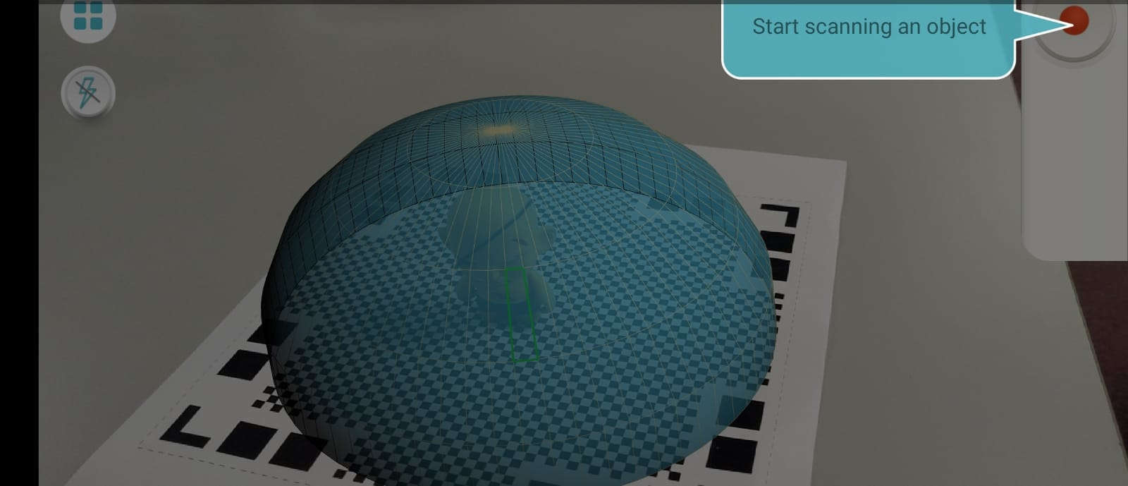
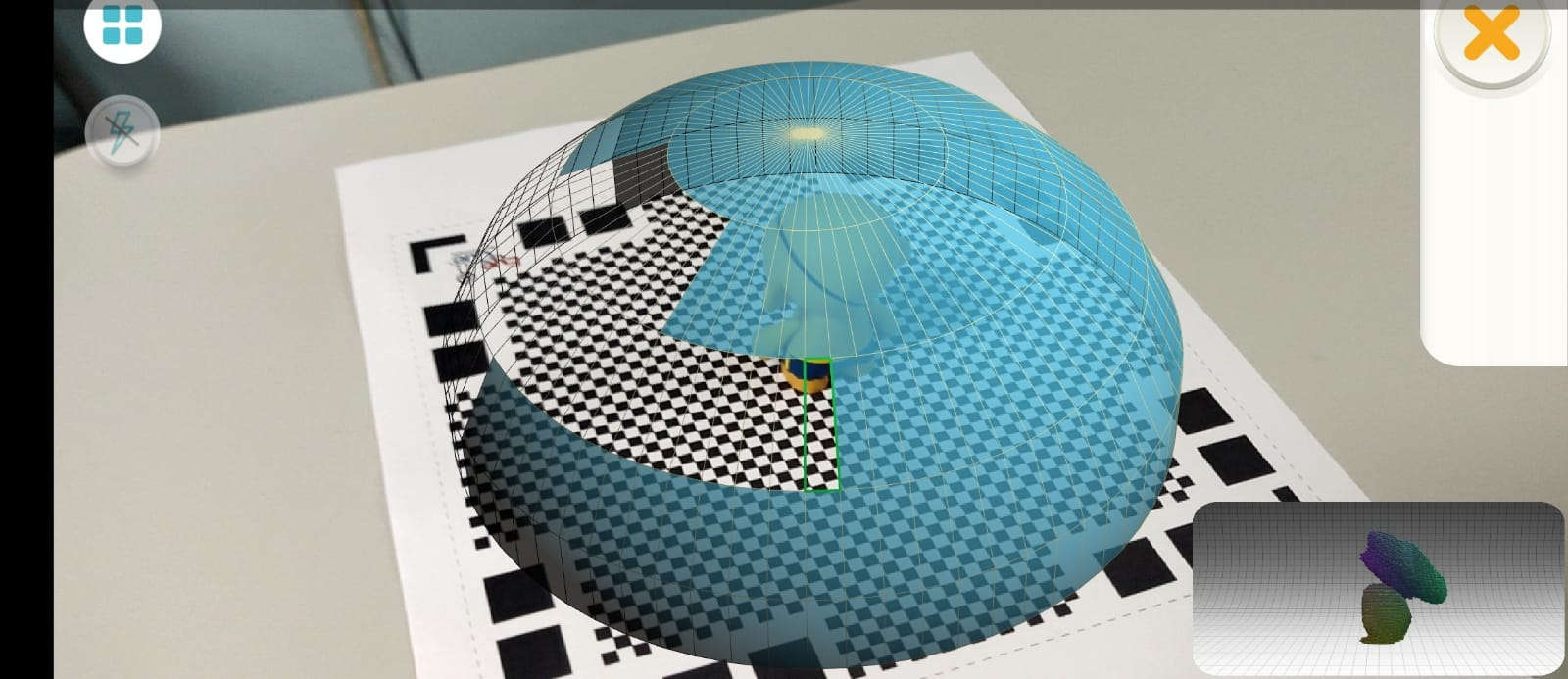
Then, I utilised that mat, by placing my 3D model in the center of it. Following the AR dome generated, I was able to orbit the camera around it to capture the the image more accurately, as the segments that made up the dome disappeared as my orbit action matched them.
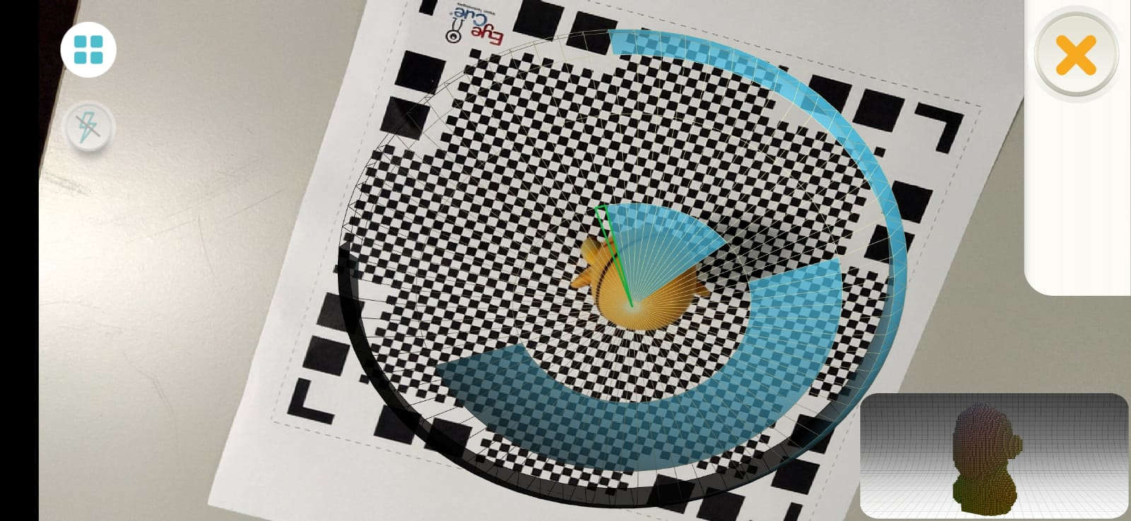
Once I was satisfied with the data captured, the app proccessed the image for editing / exporting
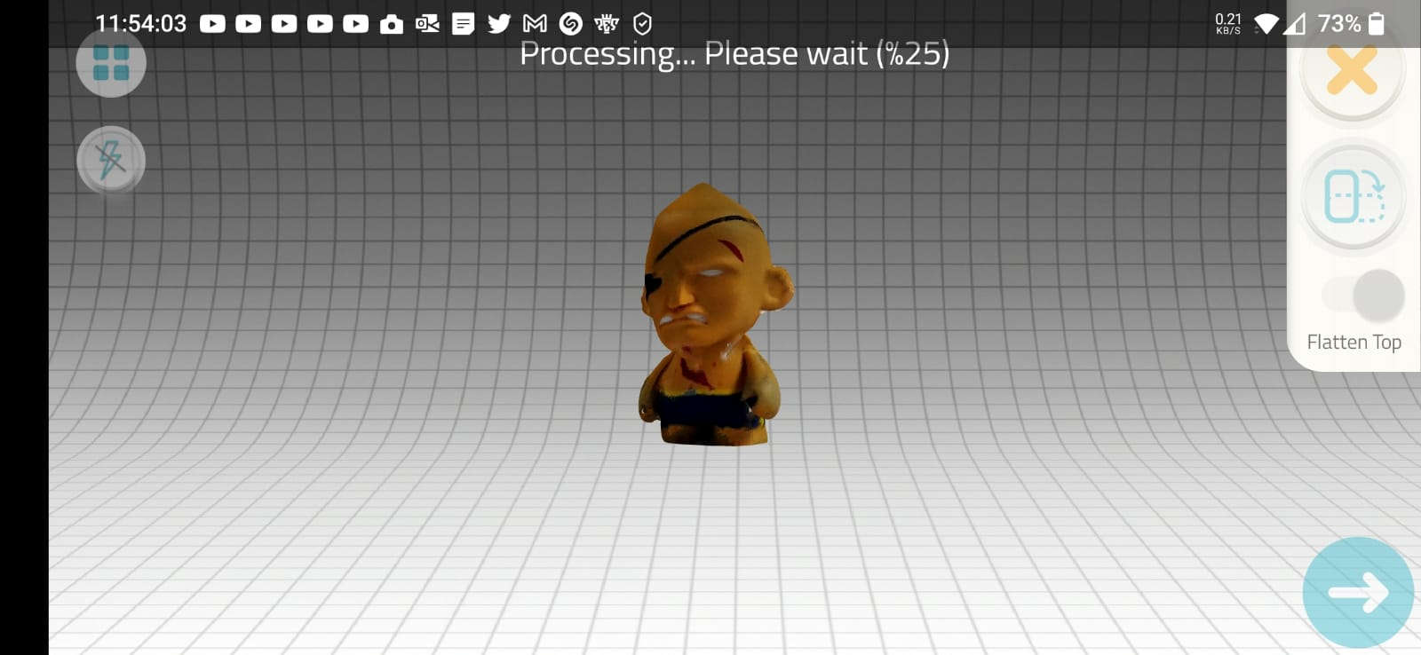
As the processing was complete, I was still able to do minor edits to the image.
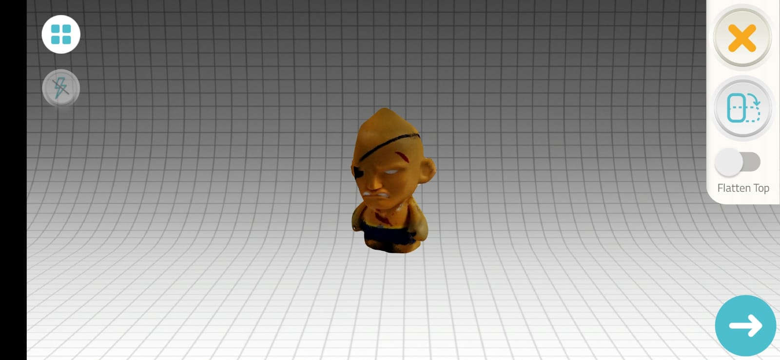
As it was a trial version I was usuing, the app didn’t allow me to export the image as the required assigment, e.g. OBJ, STL, etc. Only allowing mw to export it as a regualr jpg image instead.