17. Input Devices Group
This week I worked on defining my final project idea and started to getting used to the documentation process.
Assignment
Individual assignment:
  measure something: add a sensor to a microcontroller board
  that you have designed and read it
Group assignment:
probe an input device's analog levels and digital signals
Group Assignment
For the Group Assignment, we were tasked with probing an input device’s analog levels and digital signals. To accomplish this, we utilized the SIGLENT Digital Storage 2-Channel Oscilloscope, (as seen in the image below).
SET-UP
Upon start-up of the Oscilloscope, a Function Inspection had to be done. To achieve this, the following as done; 1. Press the Default button on the front panel to restore the instrument to its default configuration. 2. Connect the ground alligator clip of the probe to the “Ground Terminal” under the probe compensation signal output terminal.
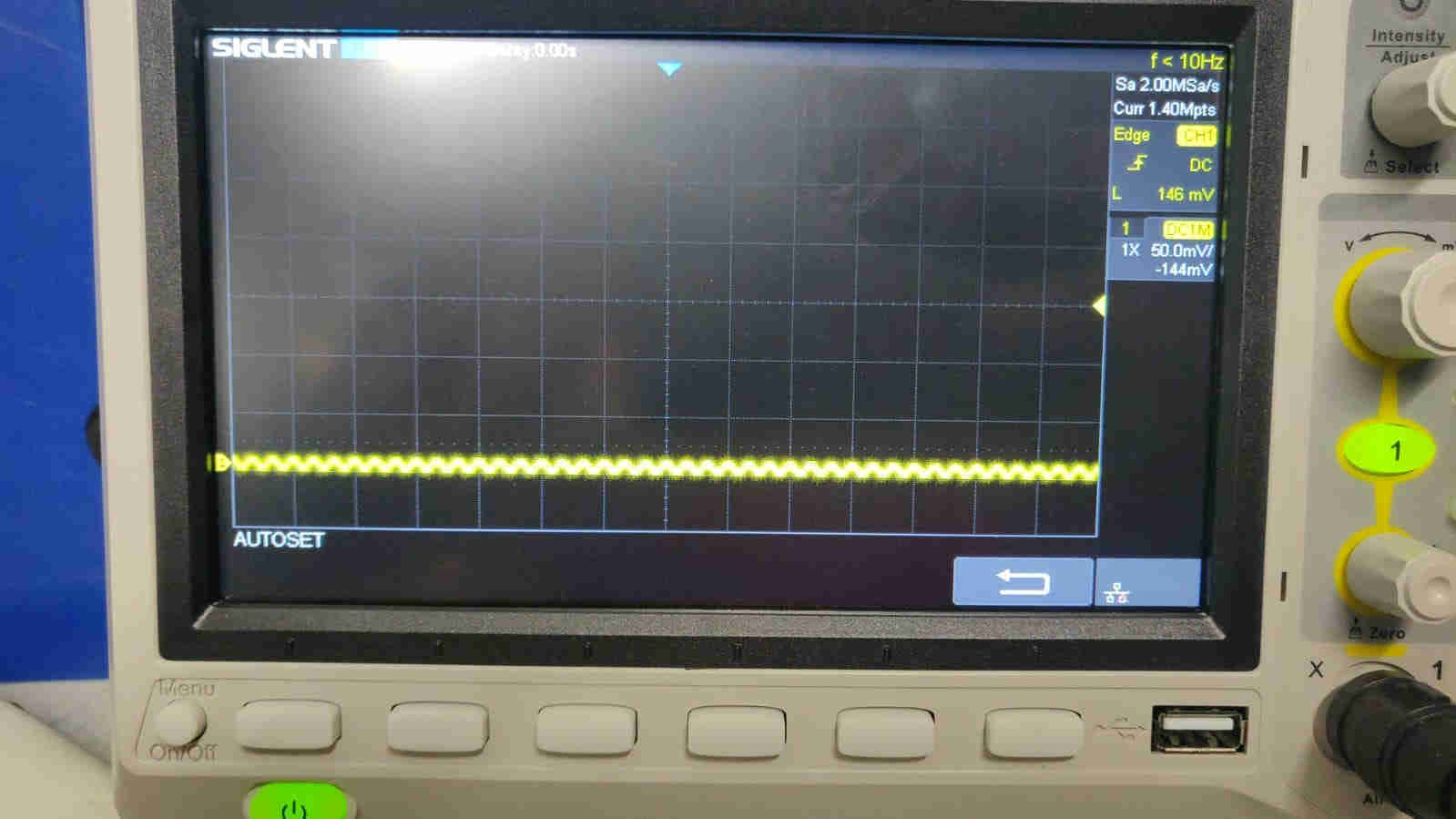
The first image above shows the Oscilloscope upon initial startup
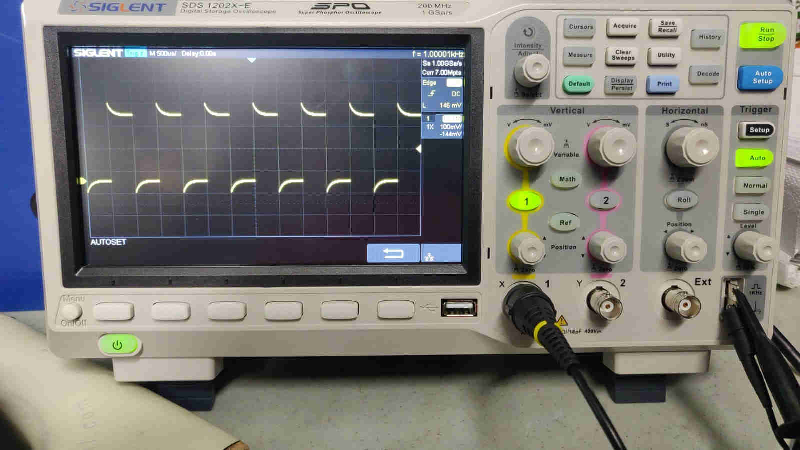
This is the signal when Function Inspection was performed (as instructed previously). It shows an Overcompensated Signal.
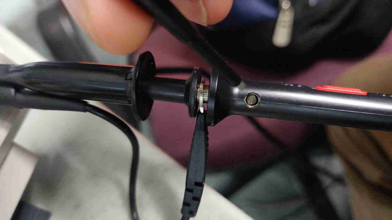
To rectify this, a non-metallic driver (flathead screwdriver bundled with the probe tool), was used to adjust the low-frequency compensation adjustment hole on the probe until the waveform displayed is as “Perfectly compensated”.
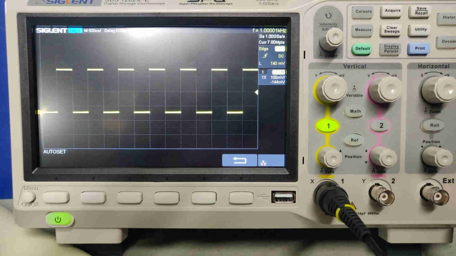
A Square Signal Waveform (as seen in the image above) is indication that the signal was “Perfectly Compensated.”
PROBING
Once the previous tasks were all achieved, the circuit probing commenced. Again, the “Hollowino” PCB, was “volunteered” by Marvin Holloway for this assignment. The very same PCB configuration was used for this task, (as seen in the image below).
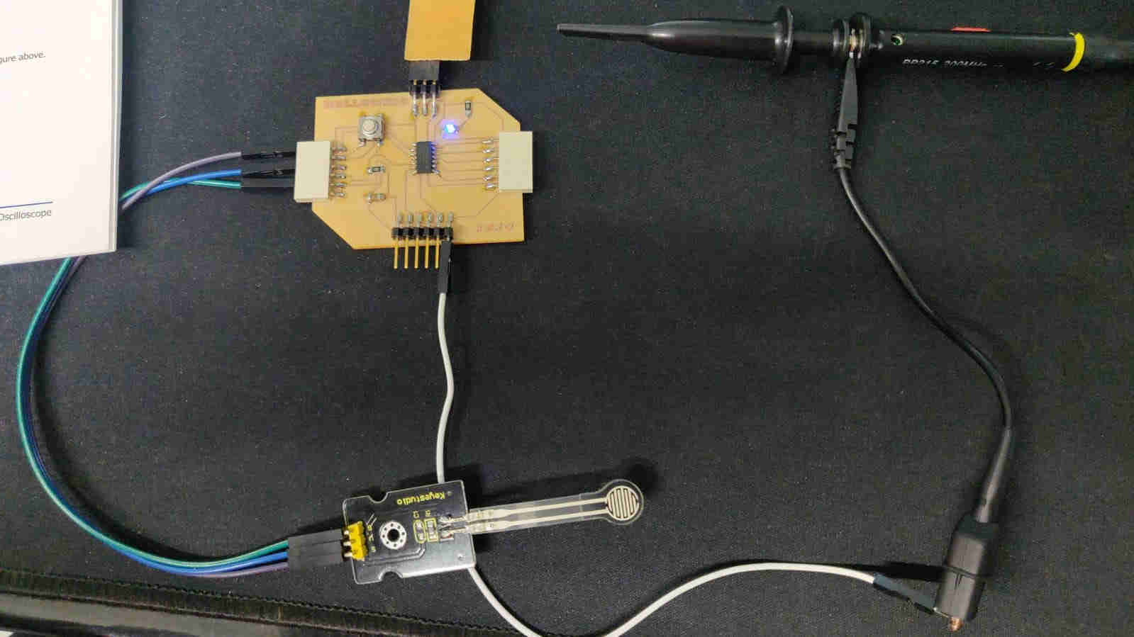
In the image above, the pressure sensor was connected (same as Marvin Holloway’s Input Devices Assignment), with the additional probe being connected.
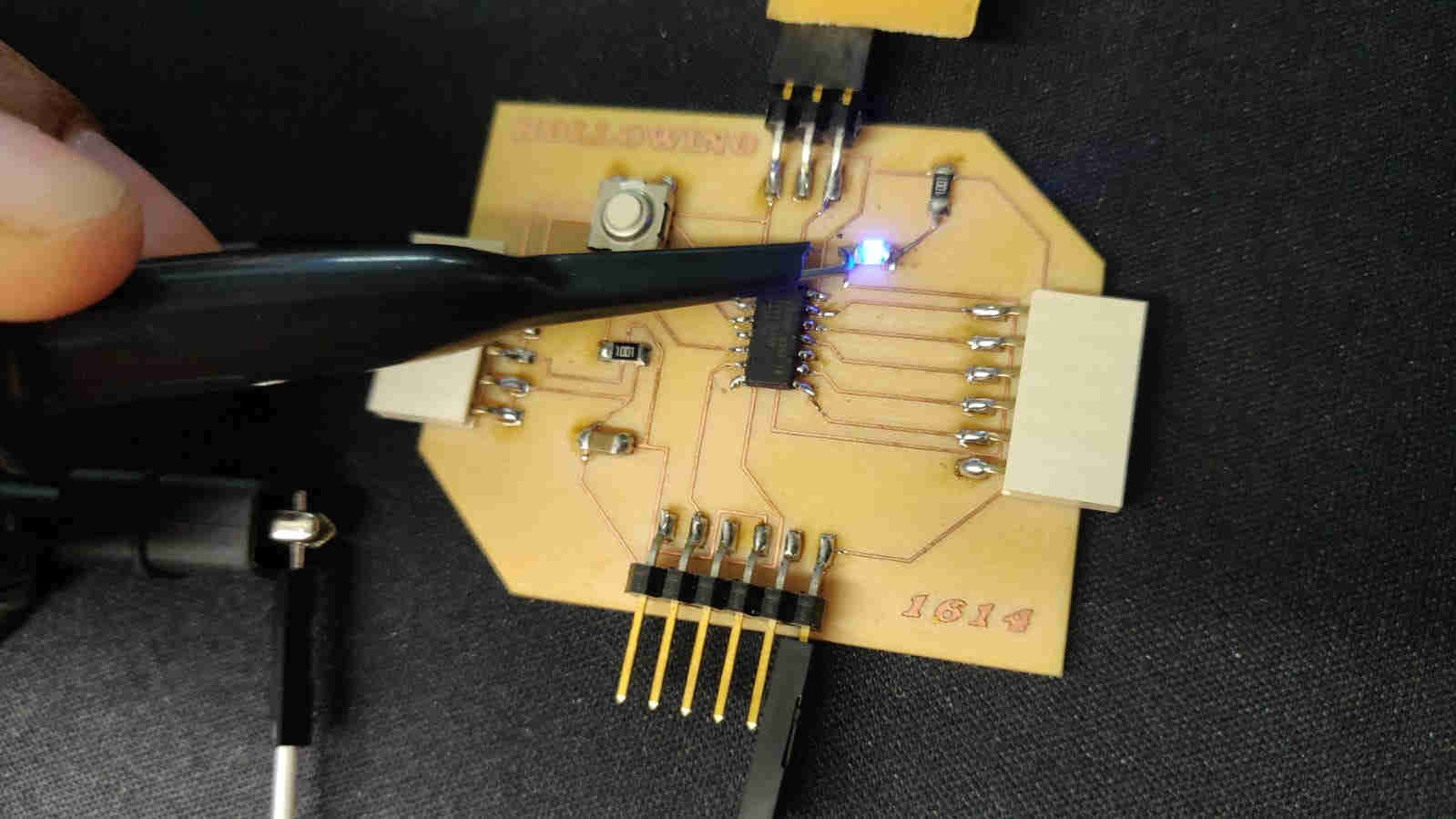
In the image above, we connected the ground lead of the probing tool (the alligator clip), to the corresponding ground of the PCB. We then took the Probing end, with its hooked tip, and placed it across the LED.
The resulting images seen below were the signal that was read upon probing the LED
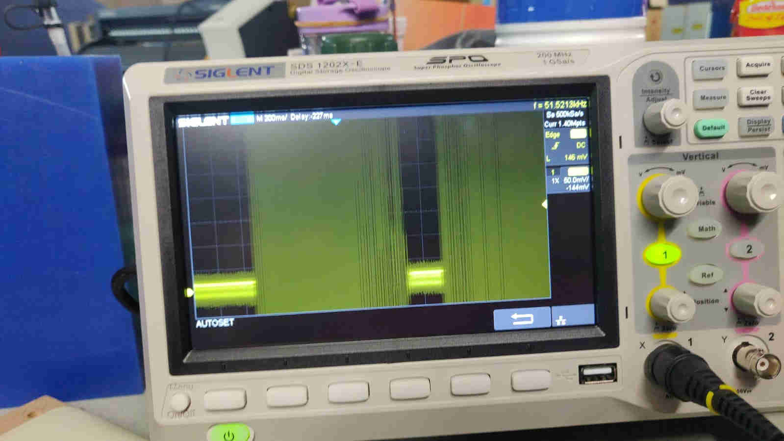
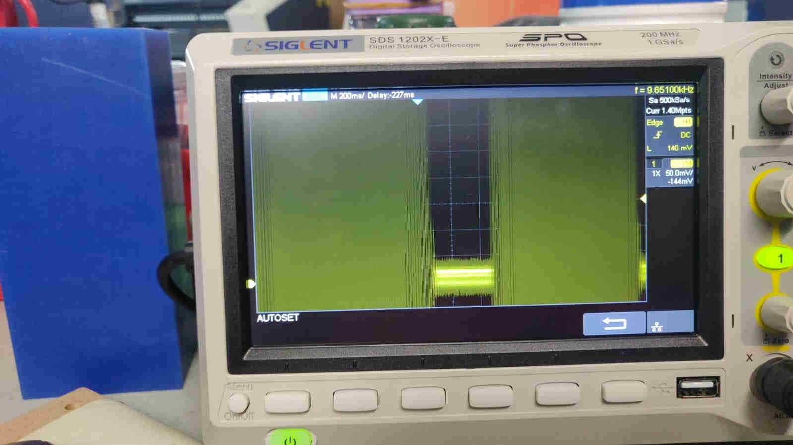
Upon observation of the signal, we can see a very dense wave with moments of very little to none being present within the signal. Each dense wave corresponds to when we physically placed pressure on the FSR Sensor. Within these results, we can see the PCB’s analog levels as well as the digital signals.