11. Input devices
This week I worked on Input Devices Assignment.
Assignment
Individual assignment:
  measure something: add a sensor to a microcontroller board
  that you have designed and read it
Group assignment:
probe an input device's analog levels and digital signals
Process
Individual Assignment
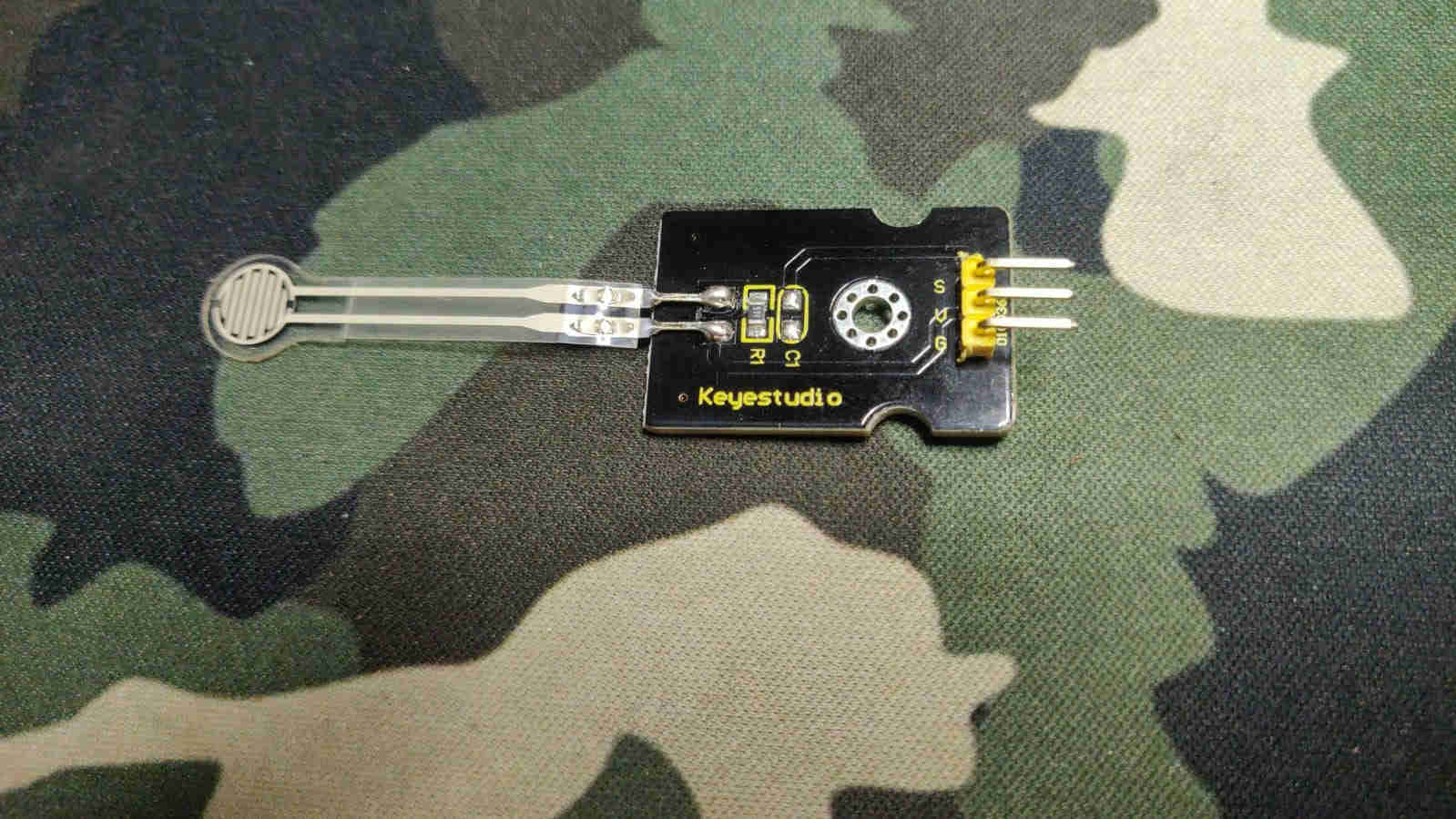
For the Individual Assignment, I decided to utilise the Hollowino. This is the PCB I would have designed, manufactured and used for my Output Devices assignment. For my input device, I opted to go with the Thin Film Flexible Force Sensing Reisitor, or FSR as it’s commonly known. This is seen in the inmage below. The sensor was manufactured by KEYSTUDIO. How the FSR sensor operates, is that it changes its resistive value in tandem the amount of pressure applied. This can be seen in the video below.
Further detailed in the video above, we can see the restance displayed on the multimeter fluctuating/ varying as more or less pressure is applied via the sensor.
Hollowino
As with the previous Output Devices assignment, my Hollowino PCB was used with the KEYSTUDIO FSR sensor to satisfy the Input Devices asssignment. Below we can see the pinout as well as the schematic for the ATTiny 1614, the chip used in the Hollowino PCB. In addition to this, is a before and after of the Hollowino board, i.e. after being milled and upon all the components being soldered (complete).


These are mentioned as they provide the ideal guidance for allocation of the I/O, input pins, when connecting the FSR sensor. From the first image of the FSR Sensor, we can see the sesnor has three pins. These are listed as follows:
- “S” (which is the signal pin)
- “V” (which is the VCC)
- “G” (which is the Ground pin)
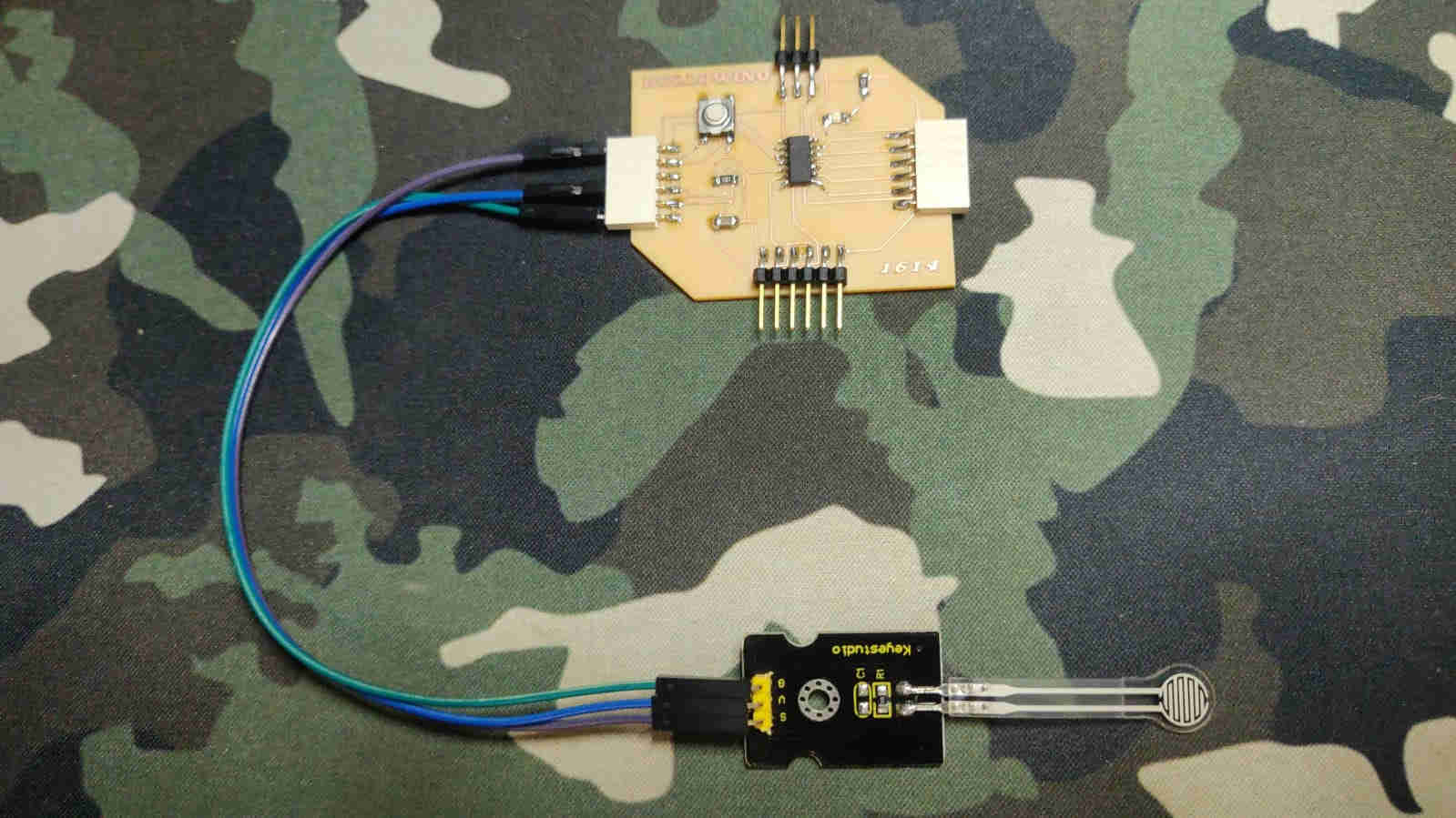
In the image below , the above mentioned pins are connected the signal pin to port pin PA4 (via the purple wire), the VCC to the VCC on the PCB (via the blue wire) and the GRND to the GROUND on the PCB (via the green wire).
CODE
For the coding of the FSr Sensor, I once again utilised the Arduino IDE software. As always, I connected my UPDI adapter to the UPDI connectors (seen as the three pins on the northern region of the Hollowino PCB), and then connected that via the FTDI cable to the PC. Once that was done, and the correct USB port was connected, I copied and pasted a sample code I found via the KEYSTUDIO website. I then made some minor “edits” (changes) to the code, (as seen in the code below), and proceeded to verify and upload it to the Hollowino board.
int s_pin = A4;
int led = 2;
void setup()
{
  Serial.begin(9600);
  pinMode(s_pin,INPUT);
  pinMode (led,OUTPUT);

}

void loop()
{
  if(analogRead(s_pin) == 1)
  {

  digitalWrite(led,HIGH);
}
else{
  digitalWrite(led,LOW);
}
  //Serial.println(analogRead(s_pin));
  //delay(500);
}
The video seen below shows the results of the code uploaded
In a nutshell, the program starts with the LED (my output indicator) at max brightness. However, when the FSR sensor is pressed, or a “pressure” is applied to the sensor, the LED’s Brightness begins to vary. As more pressure is applied it is observed that LED would dim, and lose its bright intensity as a result. In conclusion, it is obsrved that the pressure applied to the sensor is direcly proportional to the resistance of the FSR, as measured by the intensity of brightness of the LED.