12. Molding and casting
This week I worked on defining my Molding and Casting assignment.
Assignment
Group assignment:
review the safety data sheets for each of your molding and casting materials,
then make and compare test casts with each of them
extra credit: try other molding and casting processes
Individual assignment:
design a mold around the stock and tooling that you'll be using,
mill it (rough cut + three-axis finish cut),
and use it to cast parts
extra credit: use more then two mold parts
Individual Assignment
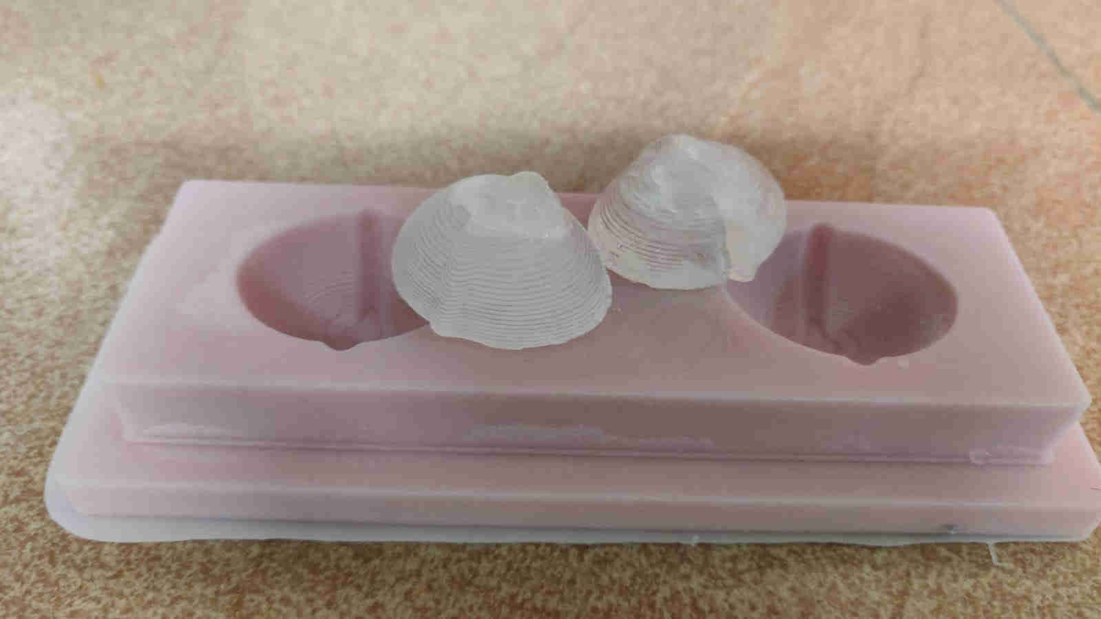
For my design, I decided, at first, that I would create 2 “Acorns”, just a random design that popped into my head at that point in time. The inspiration for my design came naturally to me, as I observed a monotonus task performed by most people in thier respective household, and that is filling ice trays. I noticed that said task is essentially behaves like a one part mold.
Once I was satisfied with this idea, I proceeded to utilise the ole reliable Fusion 360 software to design my model. This was a fairly straight forward process, as I’d also identified the “Stock” material I was going to use, Machining Wax. As we had a variety of cut pieces, I took the option of choosing the rectangular piece, and useda millimeter ruler to attain my desired dimensions, place it in fusion, and design my stock model.
Design
Below show a sequence of images detailing some steps of the design process.
 The dimensions taken from the stock model
 The “Acorns” (eye of sauron) was created by revolving a 2D shape 180 degrees
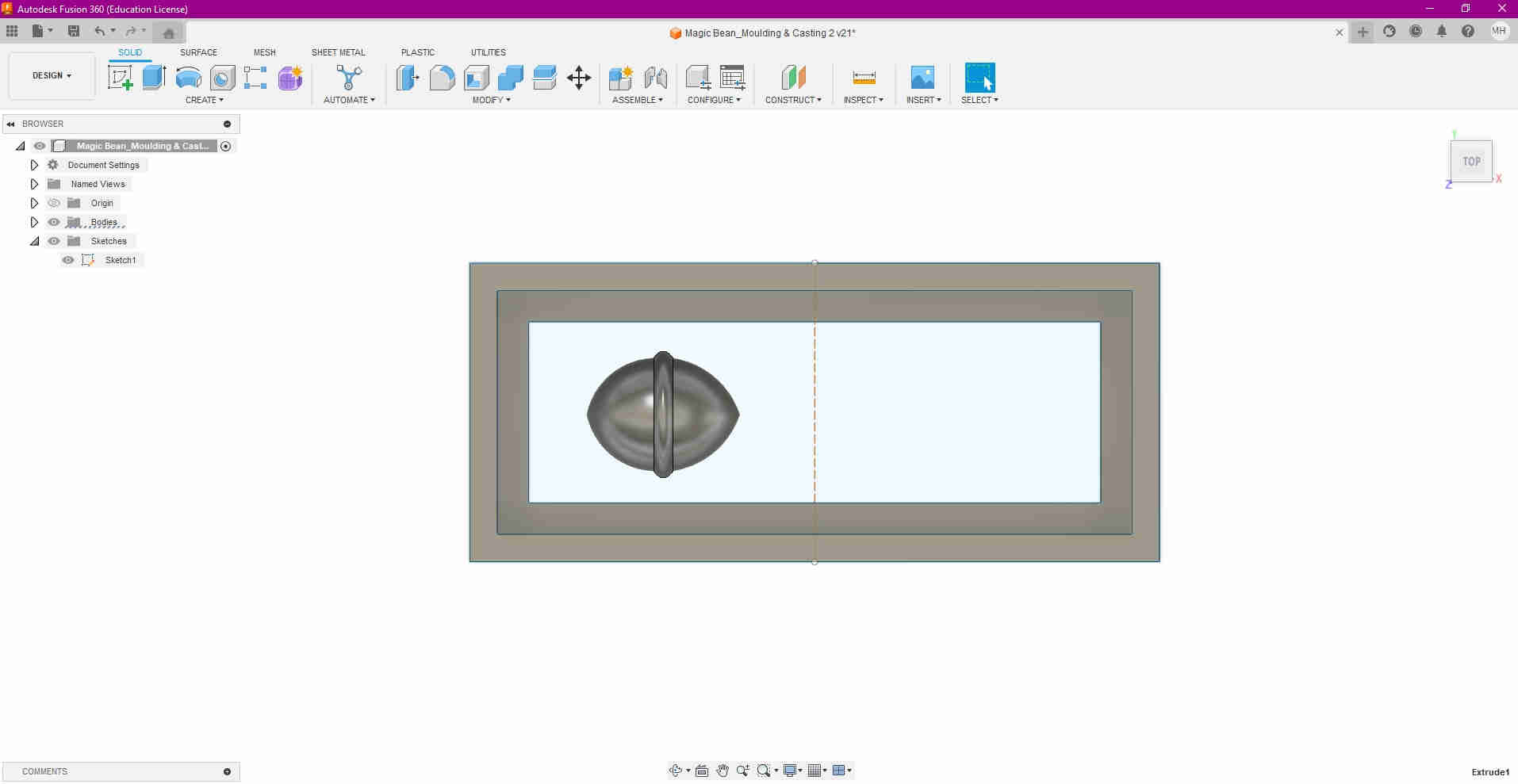
 The “Eye” was then mirrored
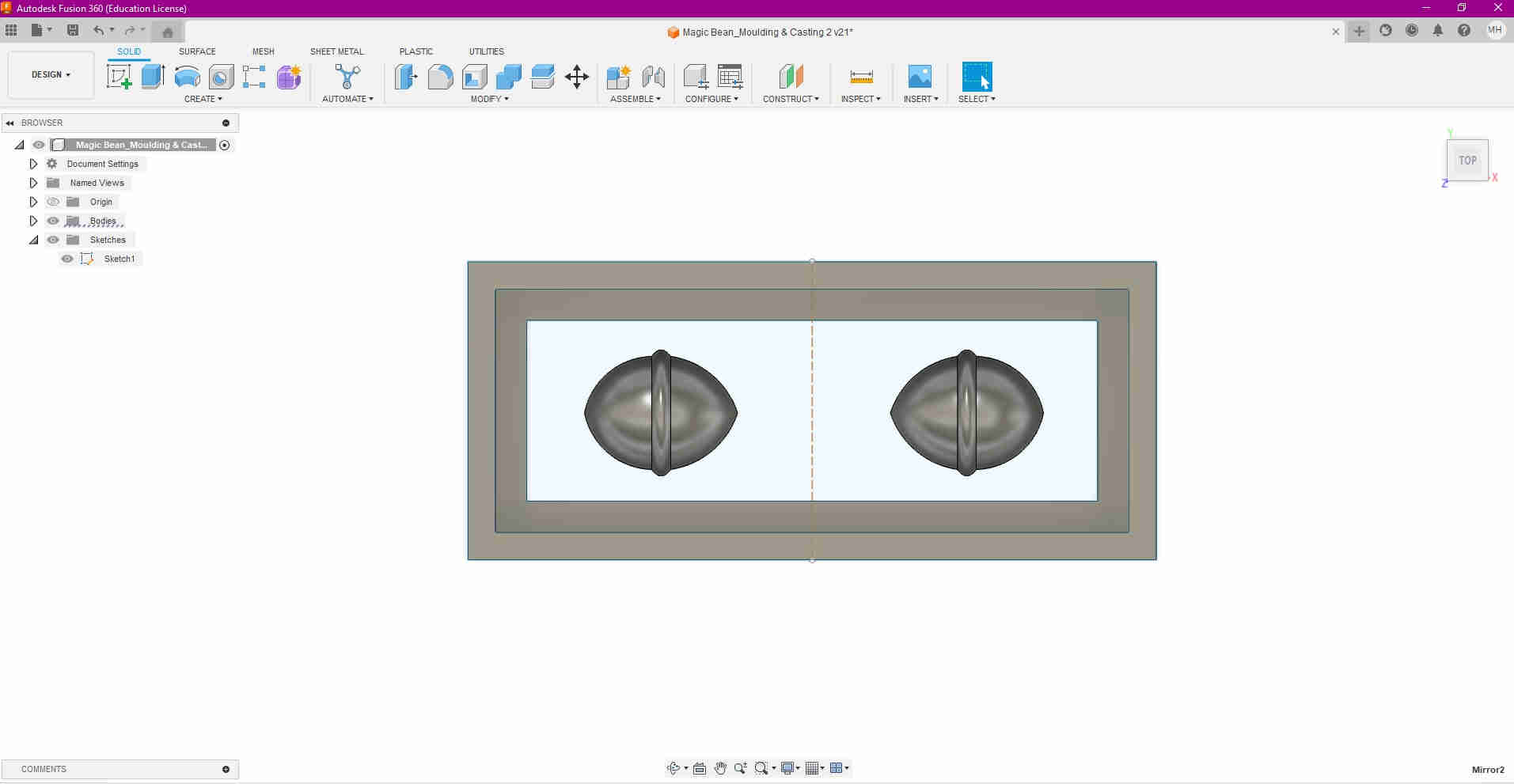
 The walls were then extruded to the stock material height. Notice the inner wall was done as a step down to compensate for the milling tool’s chuck, as a means it to not collide with the material.
Manufacturing
For the manufacturing process, the design workspace was changed to manufacture within the Fusion 360.
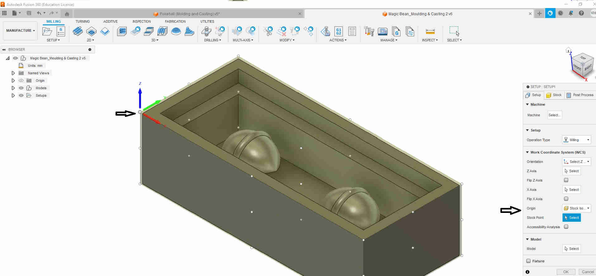
Firstly, I choose Setup, and milling as my operation type. I then changed the orientation, as seen in the image below, under the WCS (Work COordinate System). I chose Z, X as the axes for the orientation.
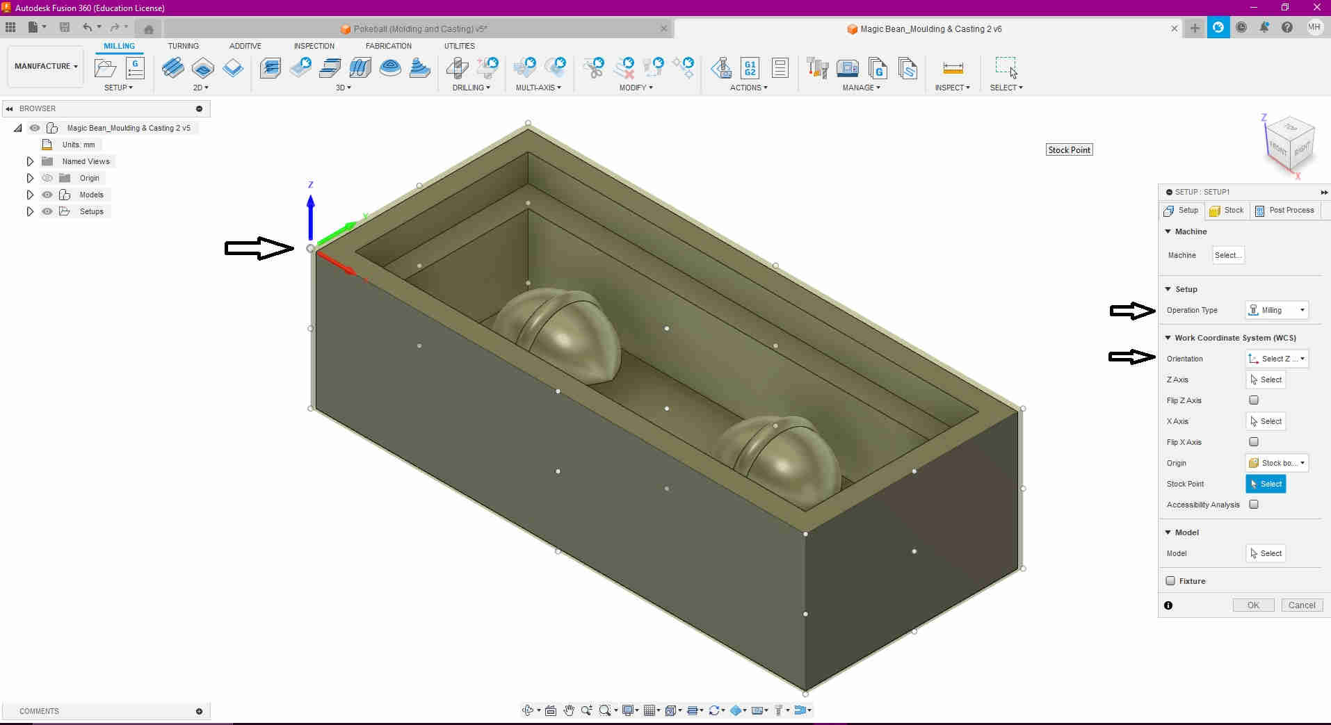
Secondly, I set the zero point, or orgin as the top left hand corner of the model
Thirdly, to determine what would be milled, I ensured that the model’s body was selected.

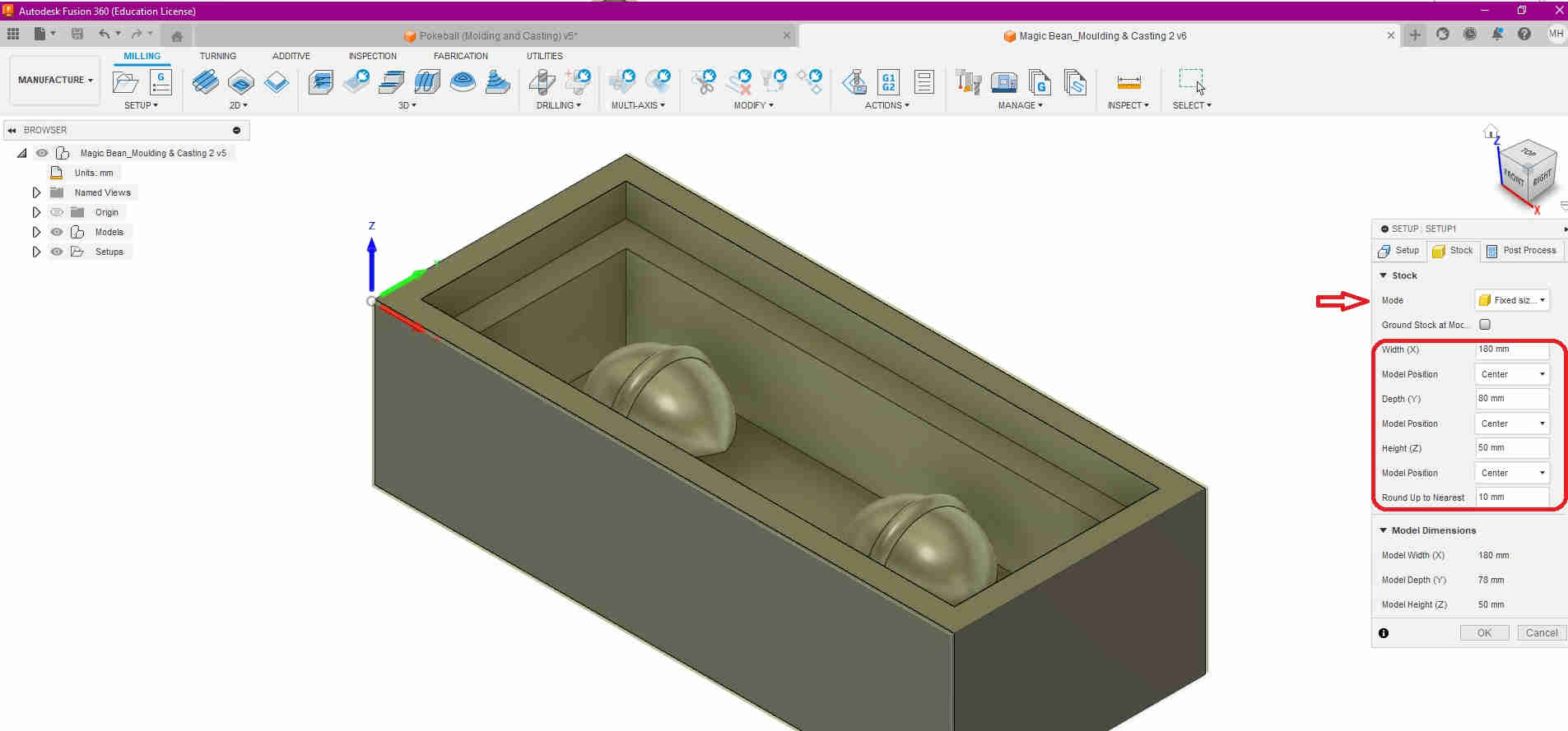
Once that was done, stock was selected, and in correspondance to that, fixed stock was chosen, as the model would be affixed to the wasteboard when milling commenced.The dimensions were then inputted in thier respctive fields, to mirror that of the design.
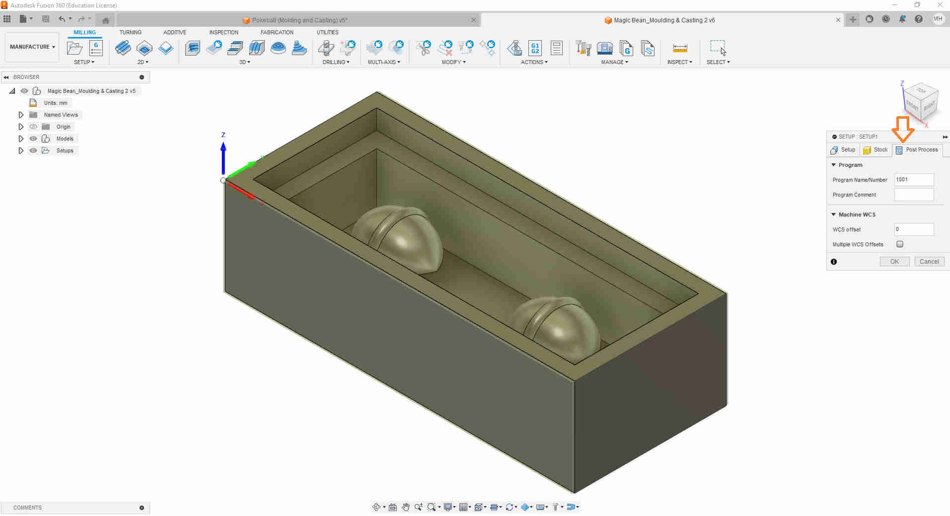
I then selected the Post Process tab, and left the values at default
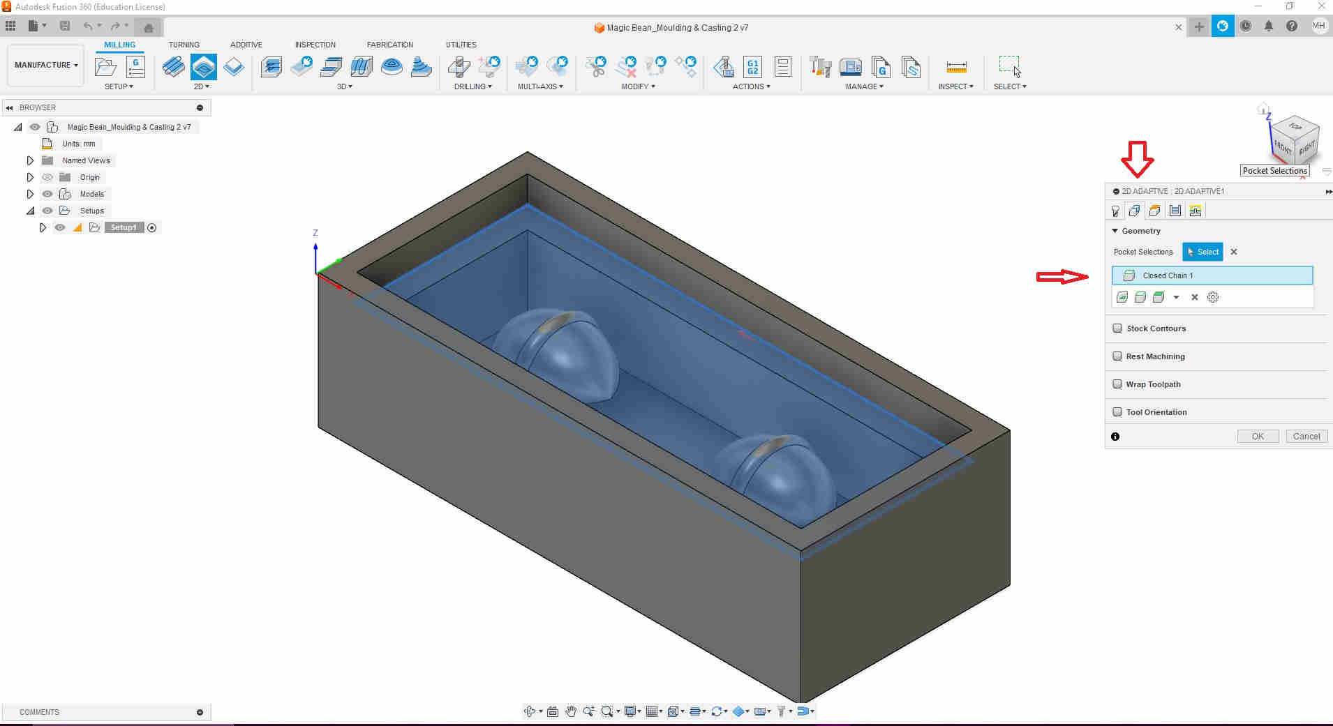
After this, 2D adaptive was selected, and at this point, I used the following tutorial seen here, to import my roughing tool (Nomad #102 (1/8-inch flat endmill) as well as other missing tools to the Fusion library. Once selected, under preset, custom was chosen, to enable me to maipulate the settings to the ideal parameters, starting with the tools tab.
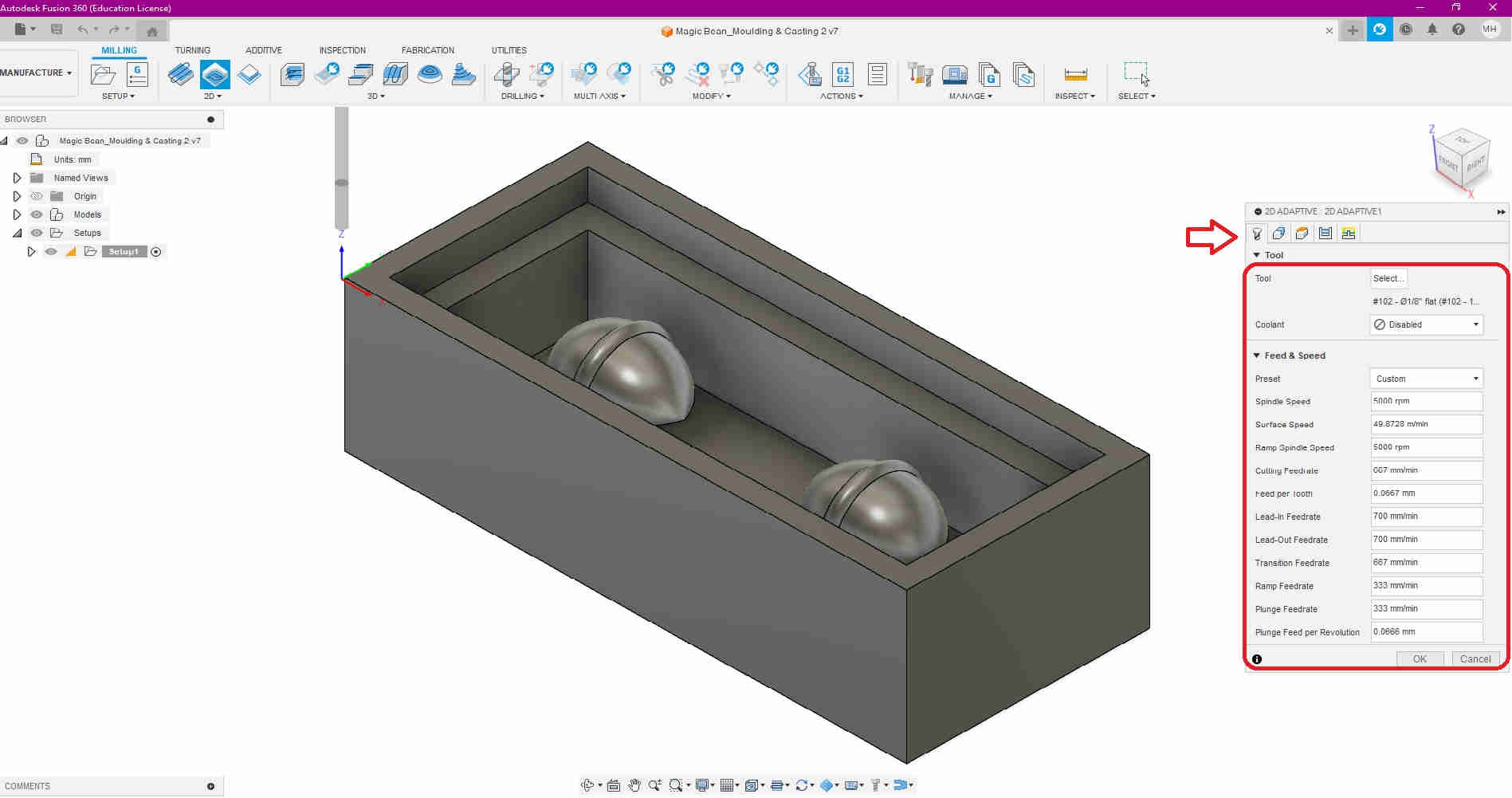
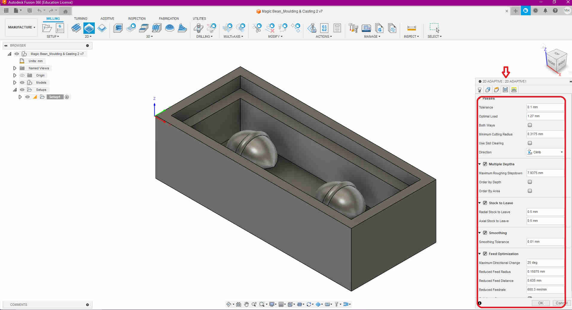
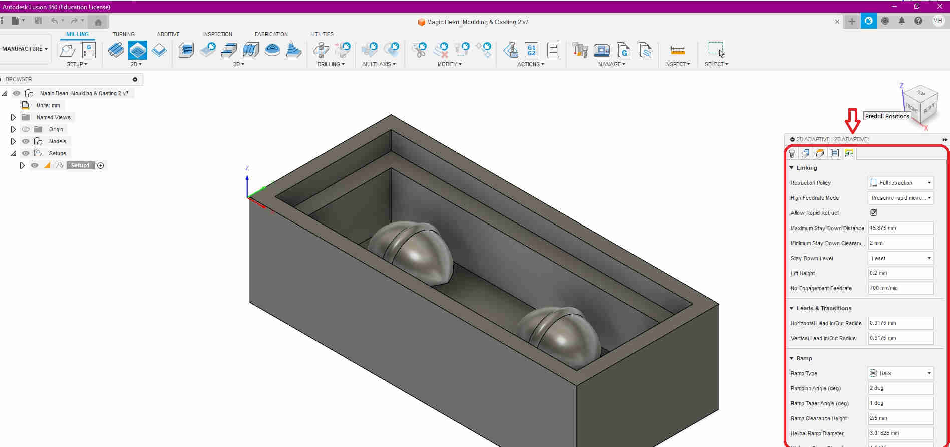
The next following images below show the settings used under 2D Adaptive, i.e.
- Geometry
- Heights
- Passes
- Linking

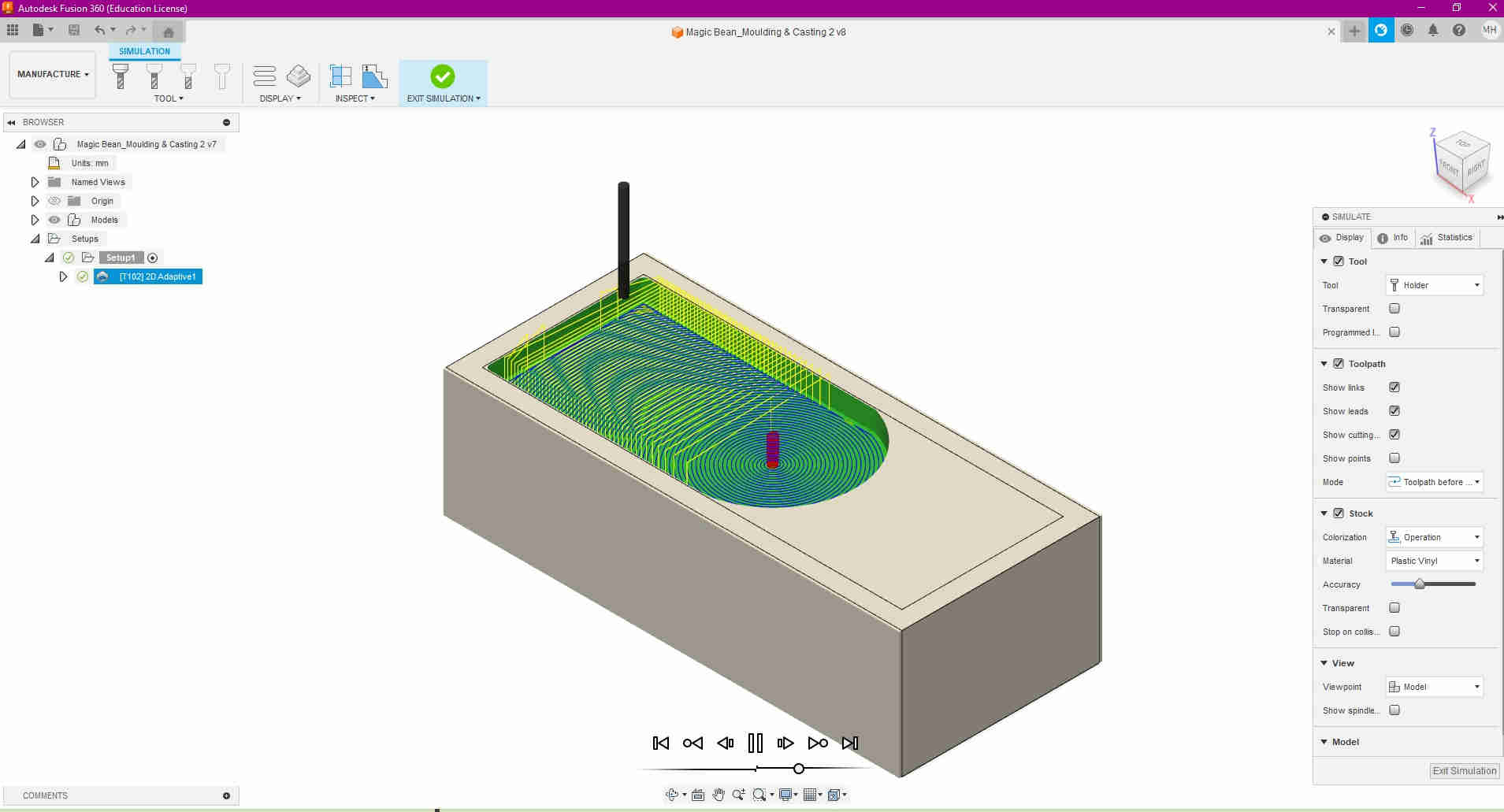
At the 2D adaptive stage, the endmill subtracts the very top of the stock model.
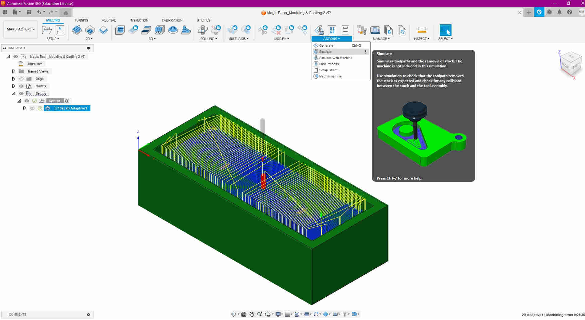
Fusion has a pretty cool feature that allows you to simulate how the tool would operate, without the hassle of testing/ running it on the machine, physically. Simulate can be found in the Actions tab on the top menu.

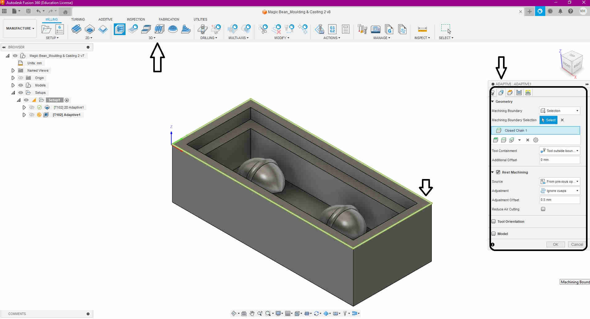
Now that the 2D adaptive was achieved, I dealt with the 3D Adaptive clearing was done. Very similarly to the 2D adaptive, the settings were manipulated to to the ideal vaules for :
- Tool
- Geometry
- Heights
- Passes
- Linking
These seetings were done, for both the ROUGHING and FINISHING stages of the 3D adaptive clearing process
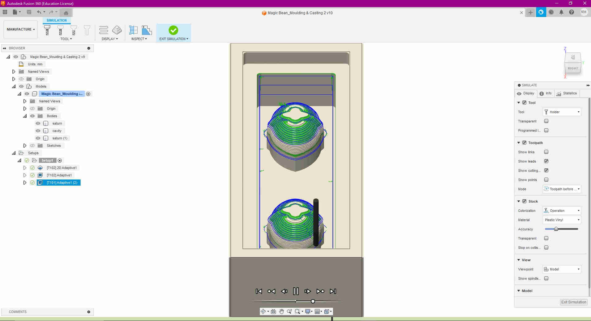
Then I simulated both the roughing and finishing stages to ensure that accuracy and functionality were achieved.
A post processor was required, GBRL, to convert the toolpaths into GCode. This video tutorial, shows the steps on how to achive this.
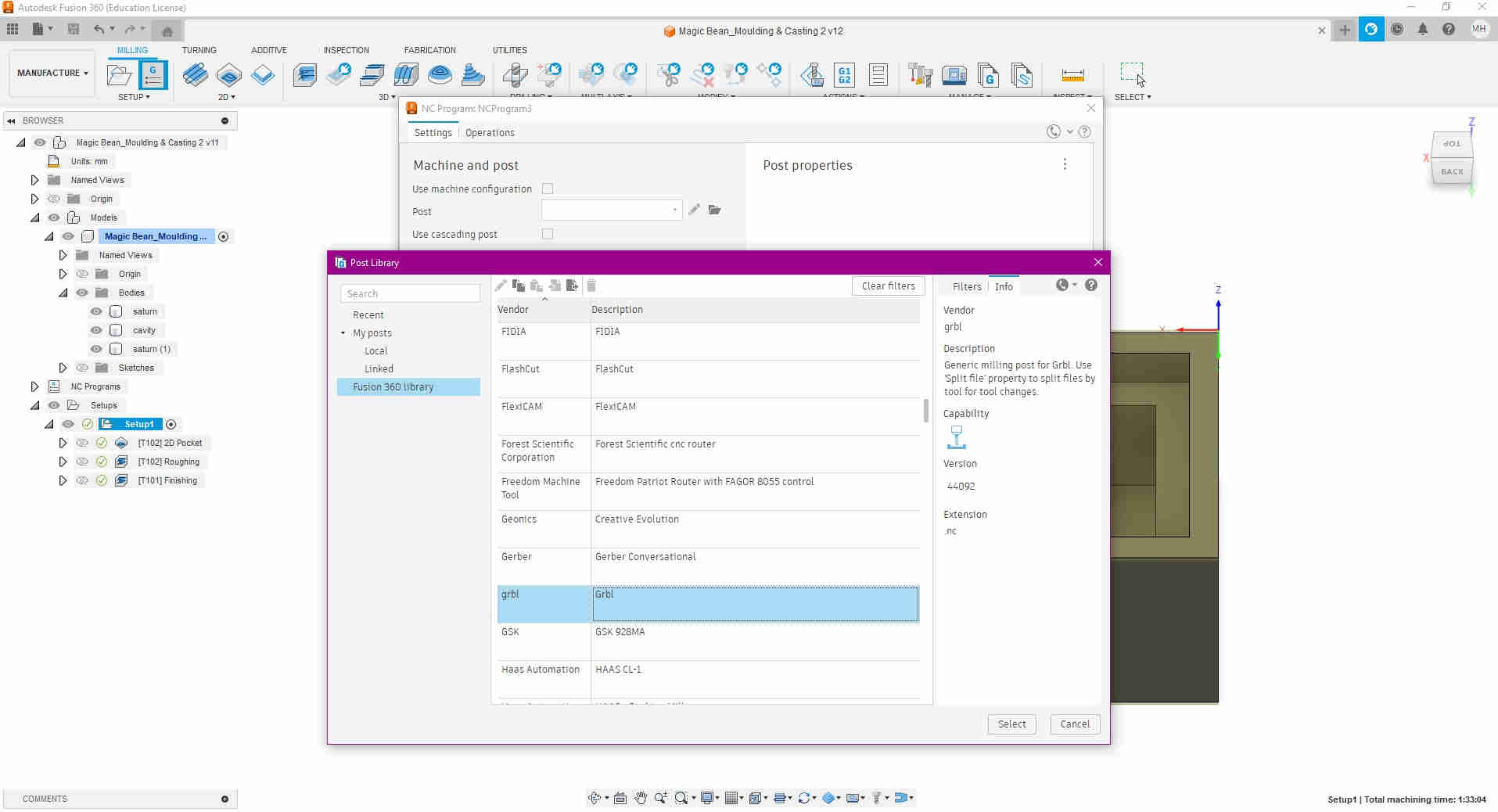
At this stage, I tested the total simulation and was satisfied. So I proceeded to create and post my NC Program. This NC program, is essentially the GCode of the Machine Wax model for the Precision Mill to decipher.


Milling
Once my GCode was aquired, I decided as a precaution to just run the simulation one last time, to ensure that there were no collisions, errors or mistakes encountered during the milling process.
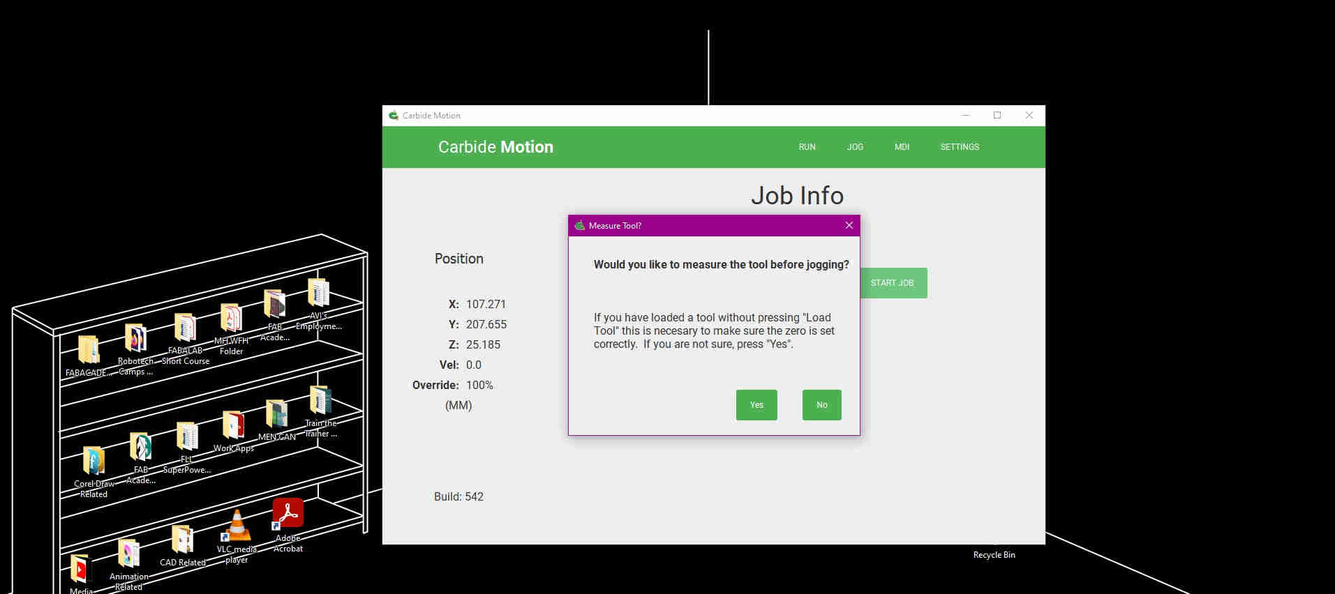
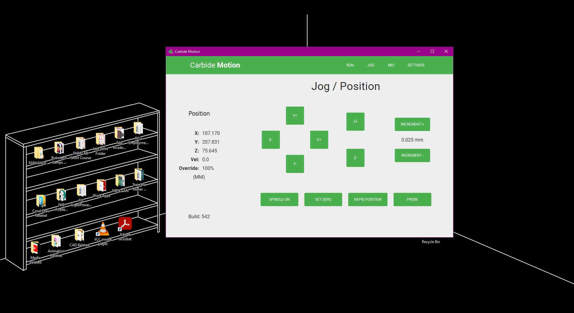
Satisfied with the simulation, I opened the Carbide Motion, and proceeded to firstly, Jog the stock piece. This essentially lets the machine measure the piece of wax being milled, in tandem with the endmill tool being used (seen in the images below)


Video
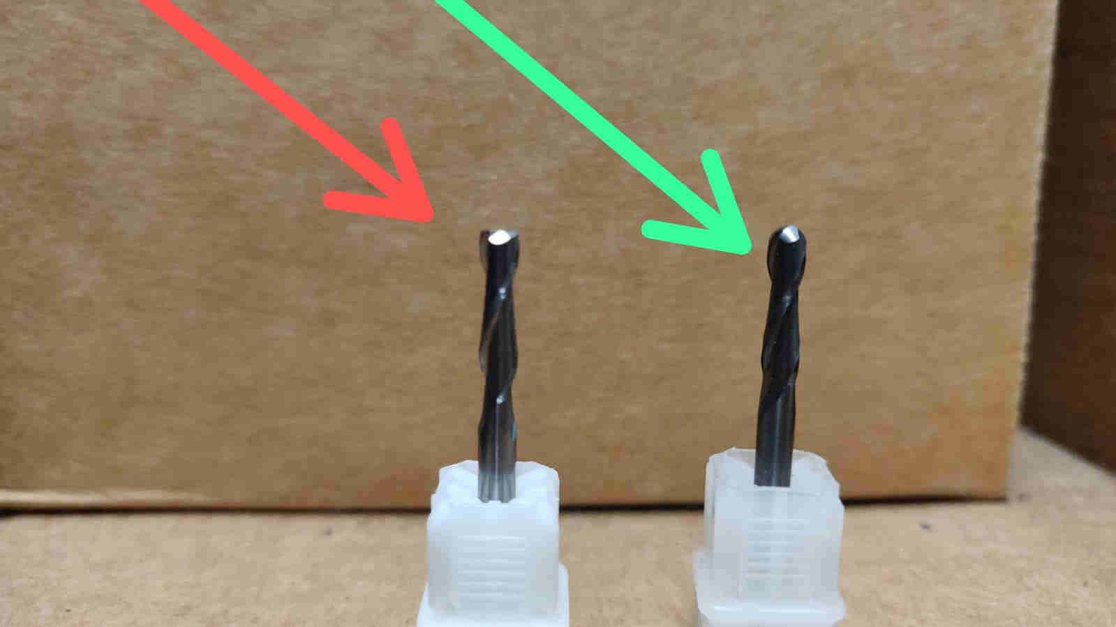
Below, are some videos, taken at various milling stages, on the NOMAD 3 CNC Milling machine, with the Nomad # 102 Square & # 101 Ballnose endmill bits (see images above)
(First Cut)
()
(Contour/ 2D Adaptive Cut)
(Roughing/ 3D Adaptive Cut)
(Finishing/ 3D Adaptive Cut)
Casting
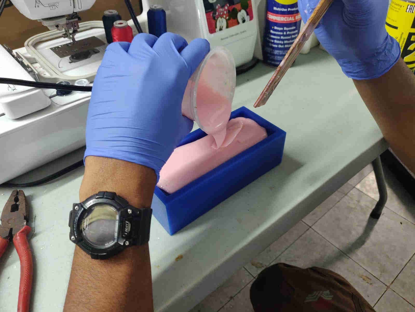
Ok, so I was at the stage where I have succeded in milling my “Positive Mold” (Machine Wax), I then focused on making my “Negative mold” (Food Safe Silicone). To do this, I used the Smooth-On Smooth-Sil 940 Platinum Cure Silicone Rubber Part A, and mixed it with the Smooth-On Smooth-Sil 940 Silicone Rubber Compound Part B. I followed this instructional video , following evry step verbatum. This can be seen within the following images seen below. Please note that the Silicone 940 Part A & B was mixed with a 10:1 Ratio, and must be mixed/ stirred well for 3 mins. The Silicone mold was then left for 24 Hours to fully cure/ solidify.
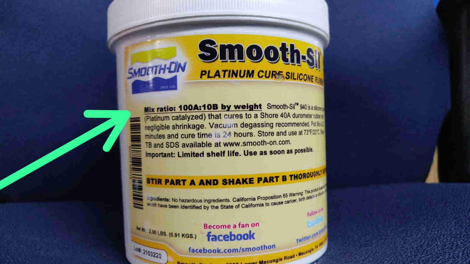
For the part A smooth sil 940, the instrcution found on the label, as seen in the image above, it is advised to be mixed with the part B with a 100:10 ratio, dependant on the amount required and weight. It should also be reiterated that the silicone mixture is of foodgrade standard, hence the ice cubes. Vacuum degassing is recommended, as it further eliminates any “missed” air bubbles, that can ba breeding ground for bacteria.
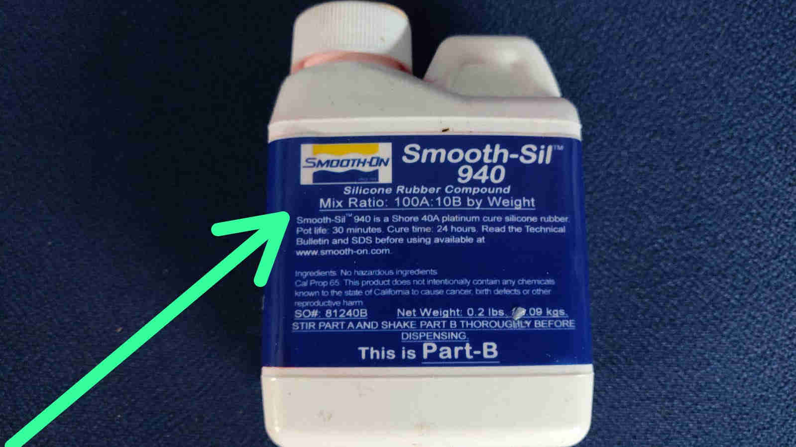
For the part B smooth sil 940, the label also retiterates a mixing ratio of 100:10, dependant on the required amount, and weight needed. In essence, 100:10 ratio, is further broken down to a 10:1 rather as mentioned, as the amount required was petite.

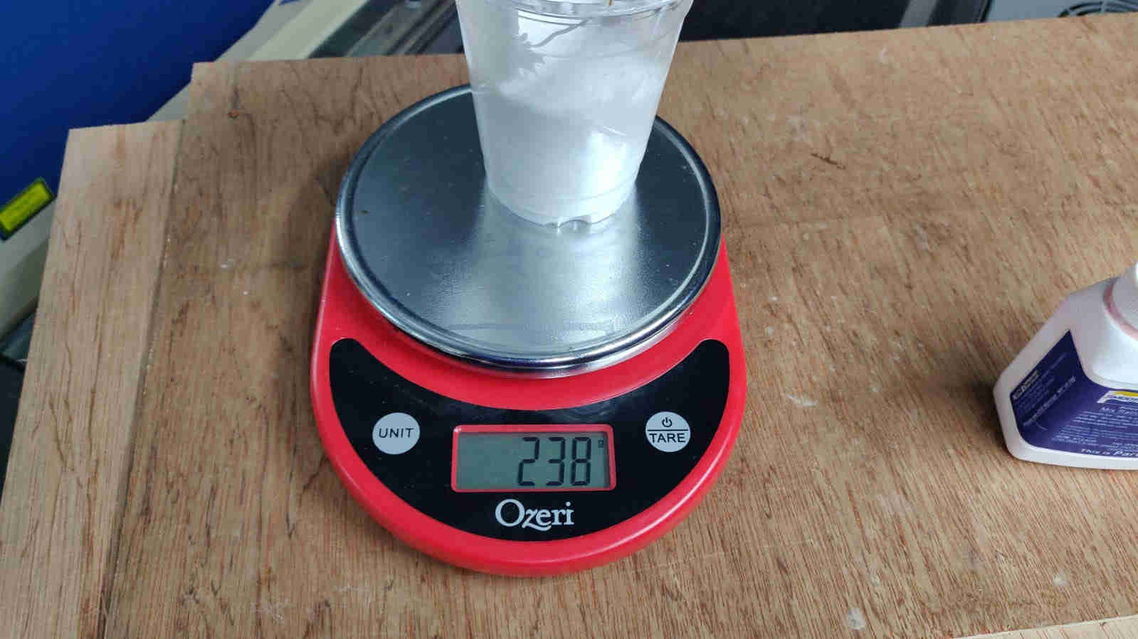
An average of 240 grams was measured for the part A

AN averaage of 24 grams was measured for the part B

Here, in the image above, Vacuum degassing is occuring


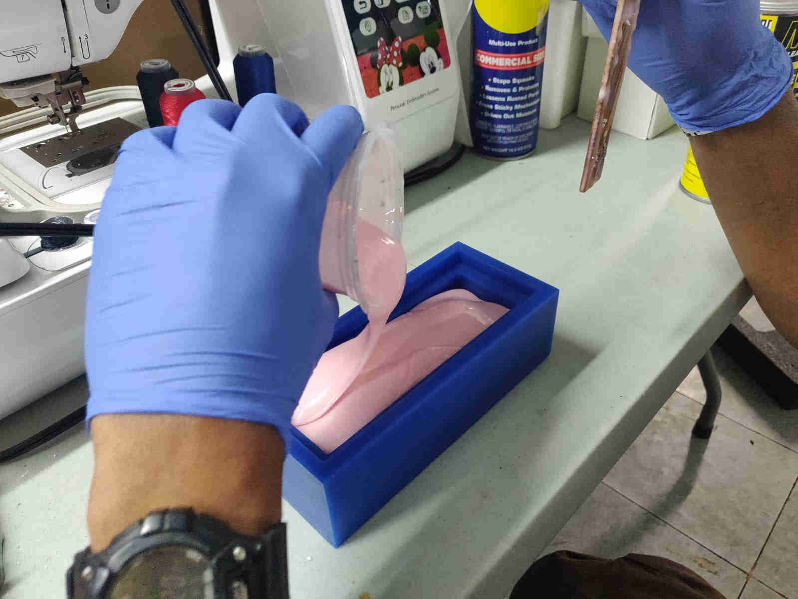
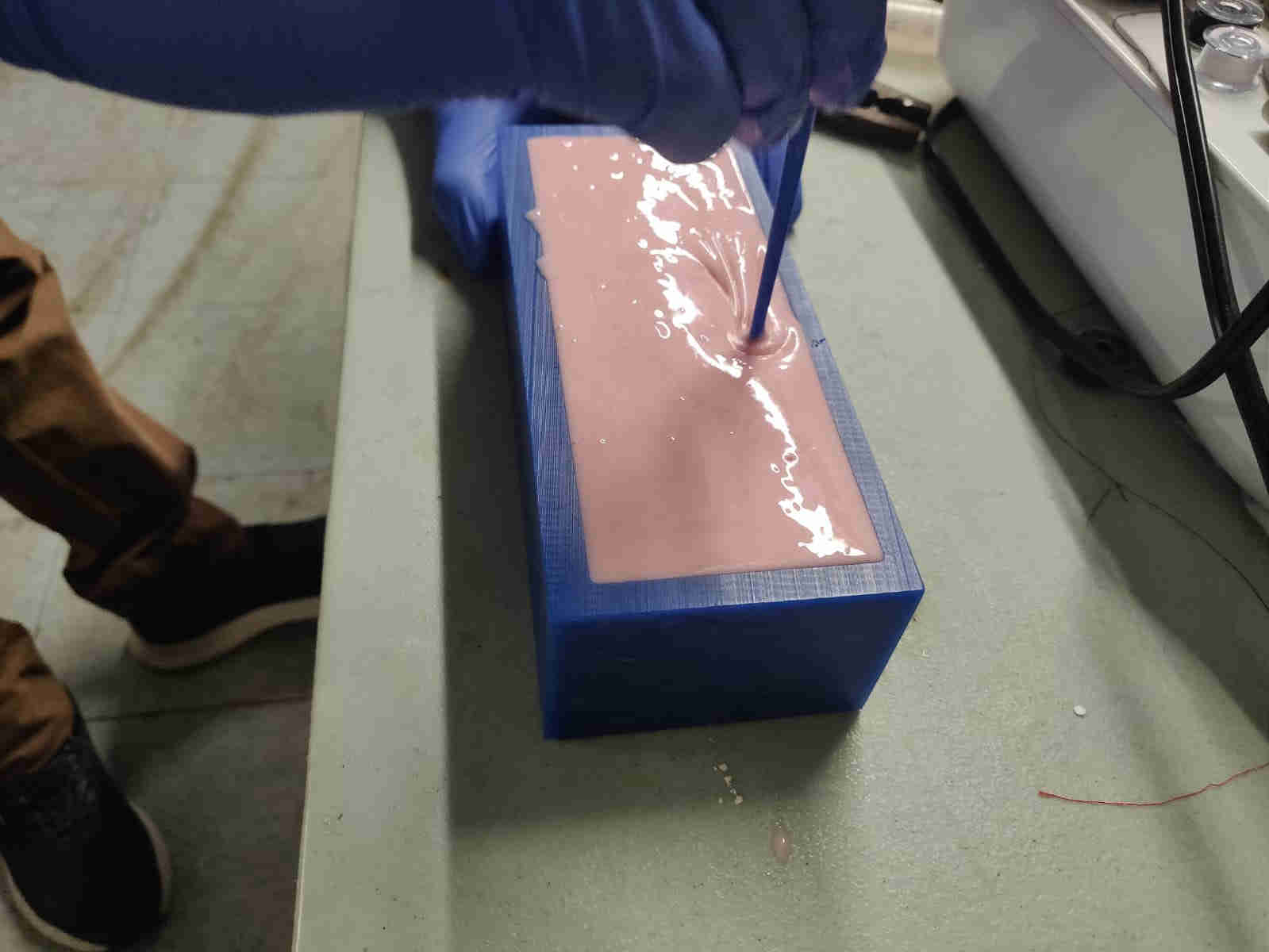
Further stirring, can aid in eliminating most unwanted bubbles
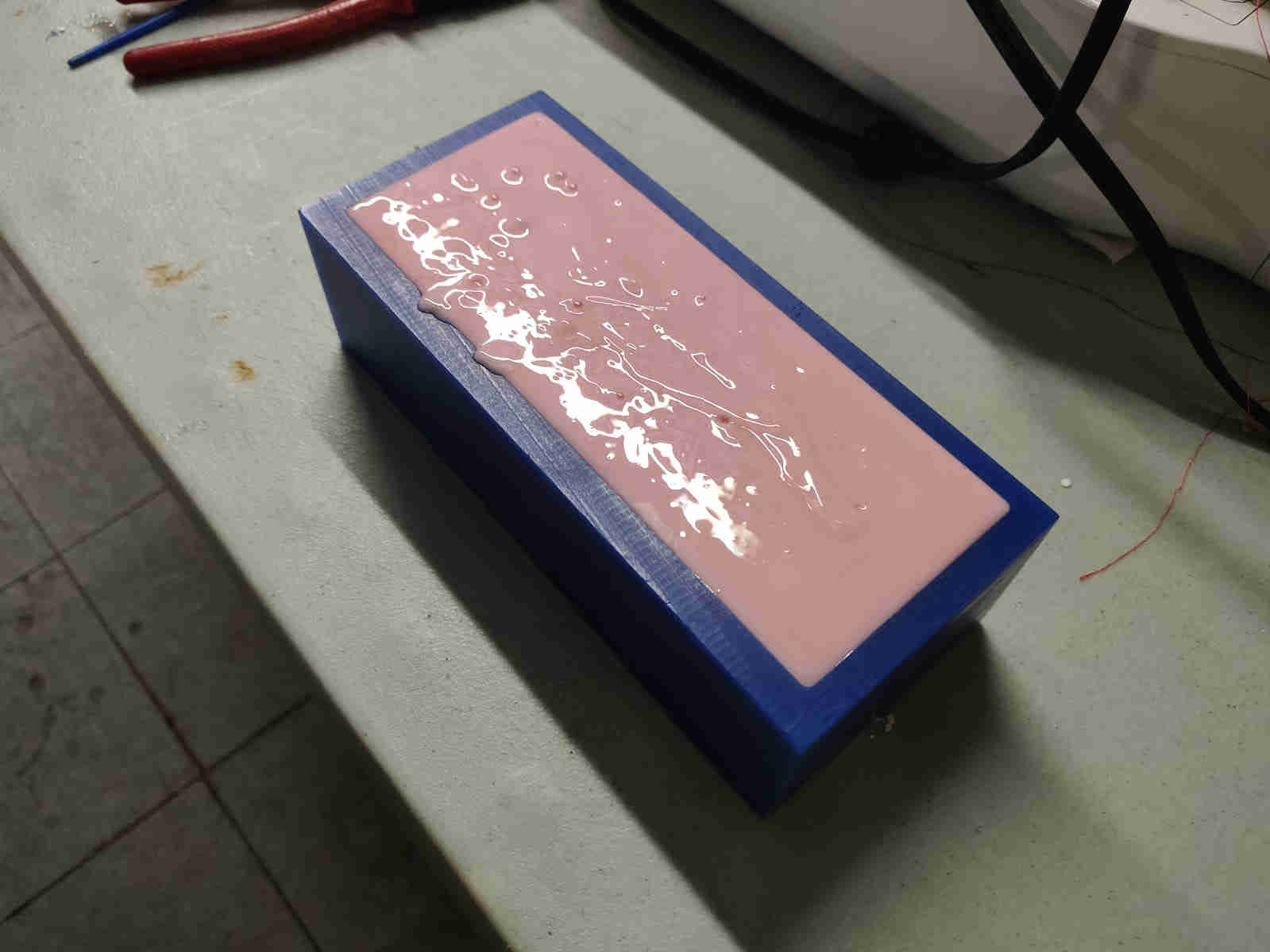
At this point the silicone was left to set overnight, 24 hours
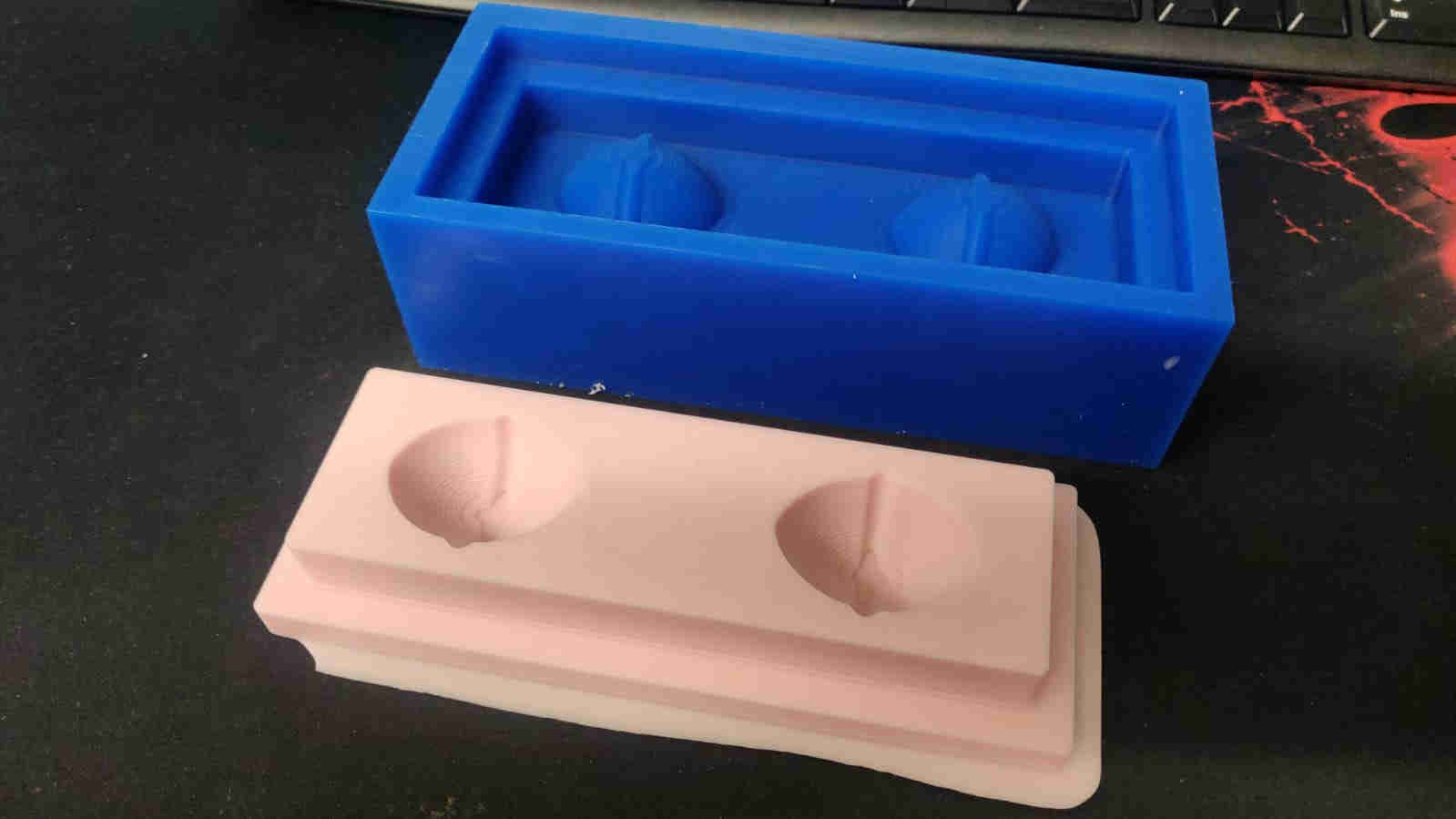
TADA! Success!