14. Interface and application programming
Assignment
Individual assignment:
write an application that interfaces a user with an input &/or output device that you made
Group assignment:
compare as many tool options as possible Group Assignment
Process
PCB/ Bluetooth
Originally, I wanted to use the “Hollowino’ board, mainly because of it’s versatility and various I/O’s. Instead I opted to using my “Superman” PCB as its been barely used, and may have felt a bit neglected. Said PCB can be found at the end of the page for my Electronics Production assignment. the end goal for this assignment was to create an app that would interface with a PCb I made, with an output/ input, in this case, the on board LED.
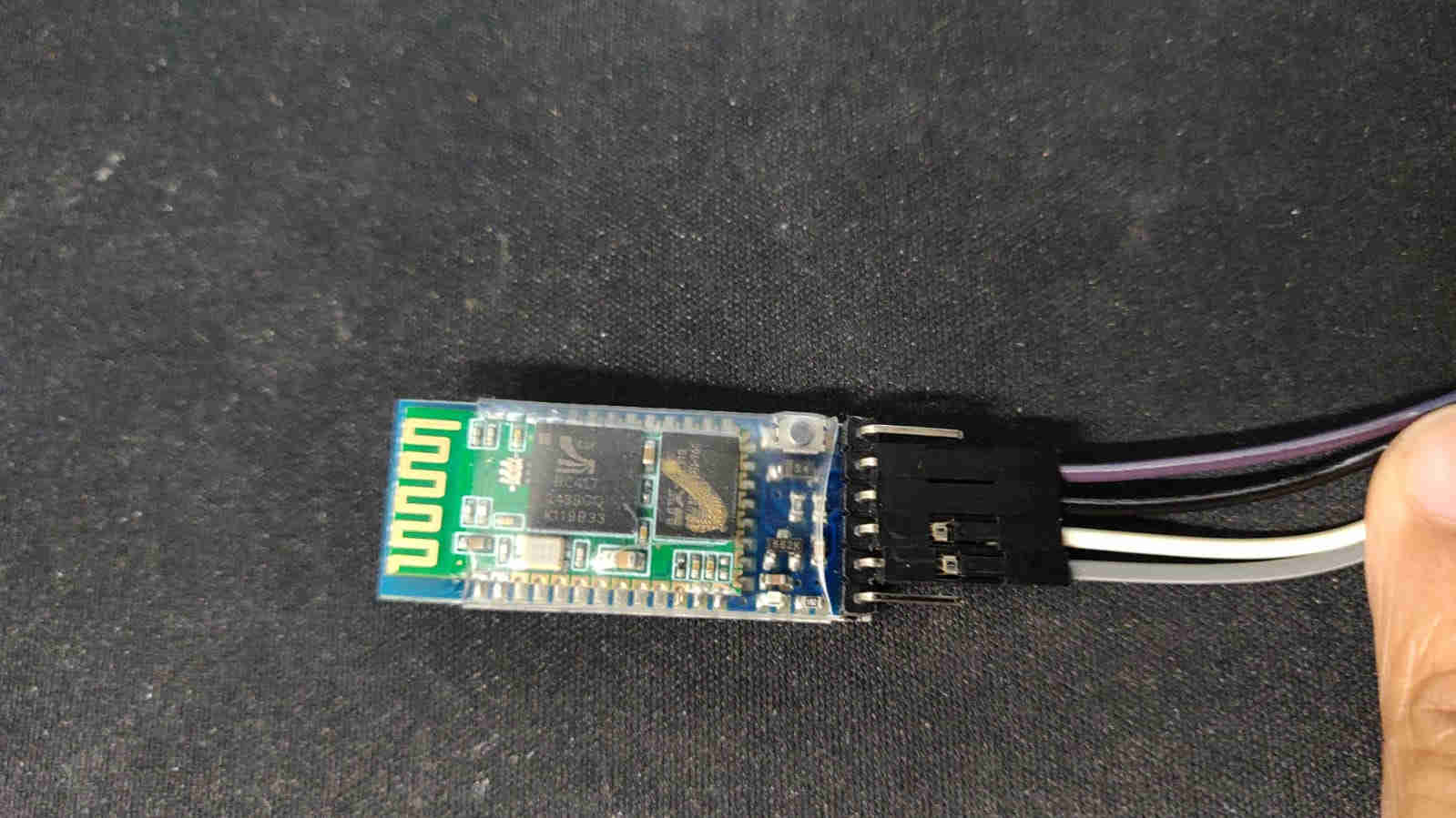
First things first I determined that if it were to interface with an app, via my android, bluetooth may be my best bet for connectivity. As such, I chose to use the HC-05 Bluetooth module to satisfy this.
I uploaded the following code to my PCB, to work with the APP
char Incoming_value = 0;

void setup()
{
  Serial.begin(9600);     // baud rate
  pinMode(4, OUTPUT);    // alocates the output as the LED
}

void loop()
{
  if(Serial.available() > 0)
  {
    Incoming_value = Serial.read();
    Serial.print(Incoming_value);
    Serial.print("\n");
    if(Incoming_value == '1')  // indicates the incoming condition (button1 when pressed) as 1
      digitalWrite(4, HIGH);  // turns the LED on
    else if(Incoming_value == '0')  //indicates the incoming condition (button2 when pressed) as 0
      digitalWrite(4, LOW);   // turns the LED off
  }
}
Connection
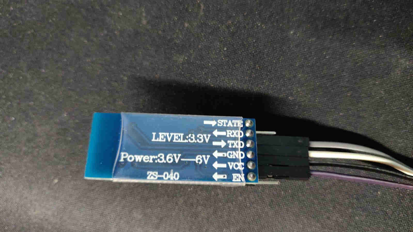
When connected my PCb to the bluetooth module (BTM), I connected it using the FTDI pins and I ensured that
PCB VCC -> BTM VCC
PCB GND -> BTM GND
PCB TX -> BTM RX
PCB RX -> BTM TX
Building the APP
For this assigment, I opted to utilise the MIT App inventor. This online tools, allowed me to easily create the app, from scratch, whilst understanding each step along the way.
Upon logging in with your email account, click “Create Apps”

Now Click New Project and name it Bluetooth
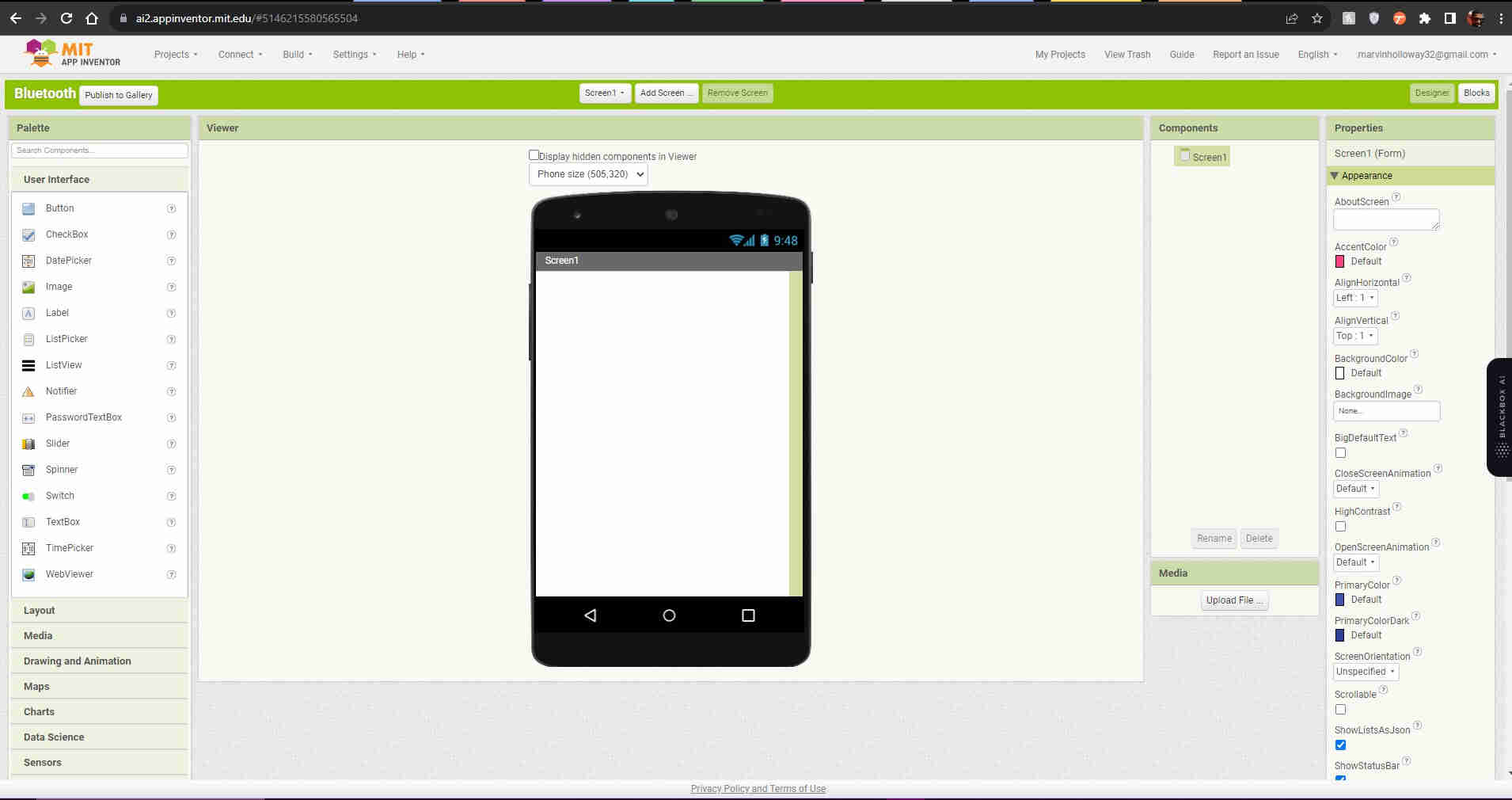
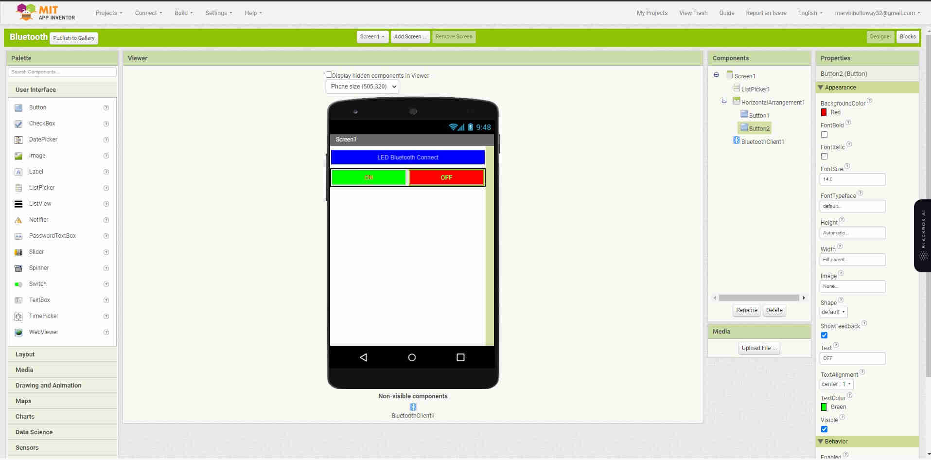
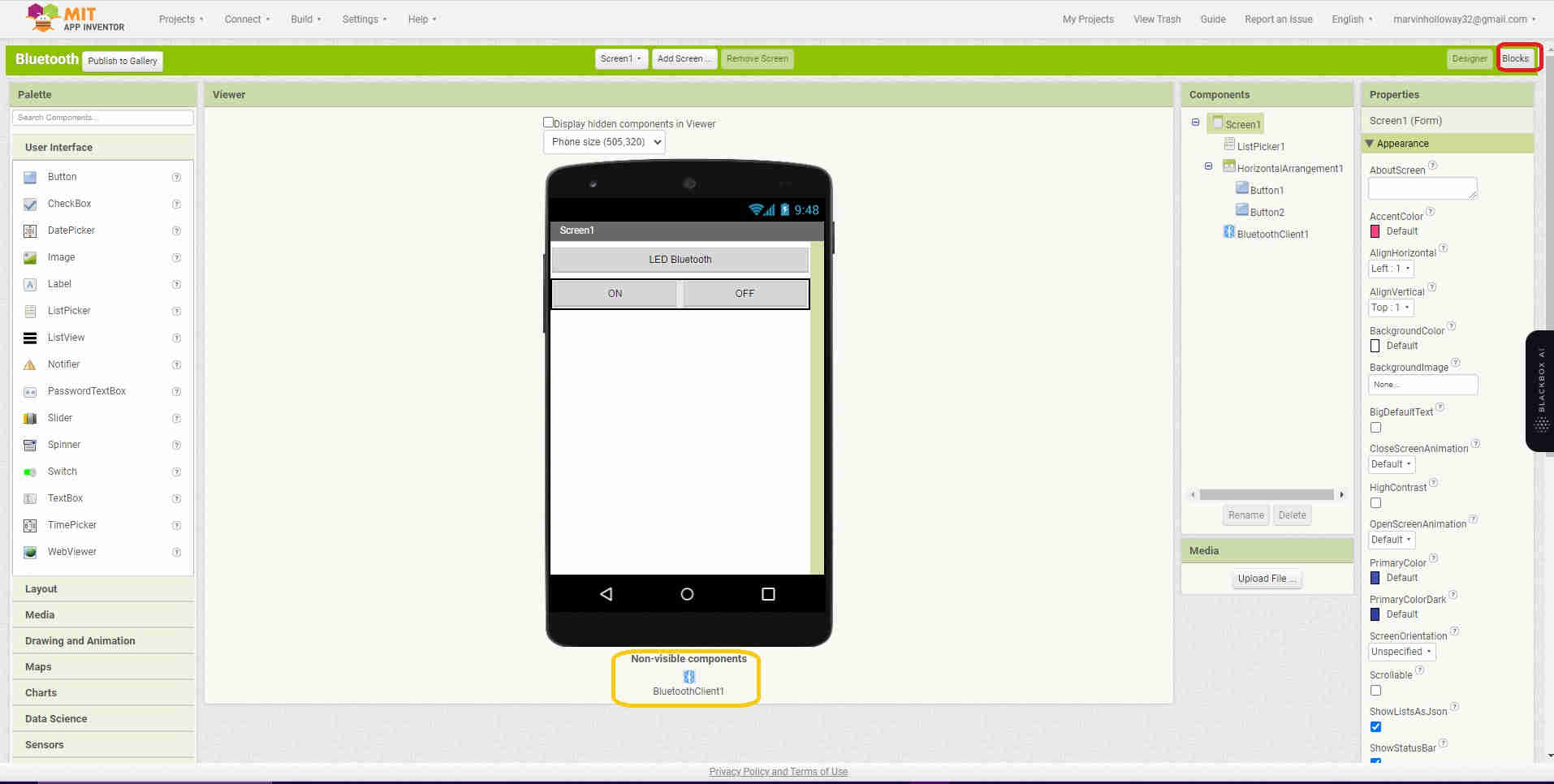
This is the Viewer workspace, it kind of previews how the app would look upon your mobile device
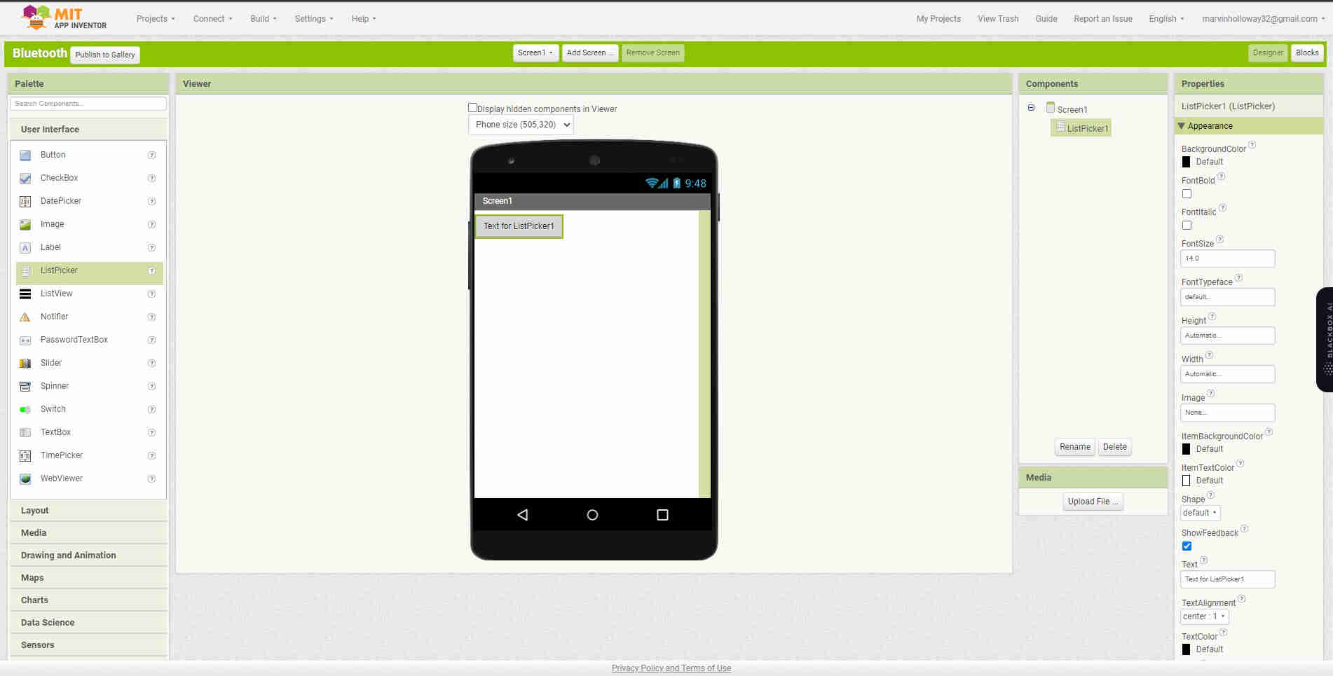
Select Listpicker and name it LED Blutooth. Select width and select Fill Parent
Select Horizontal Arrangement (under the layour heading on the left). For width, select Fill parent. Select the Button and place Button 1 and Button 2
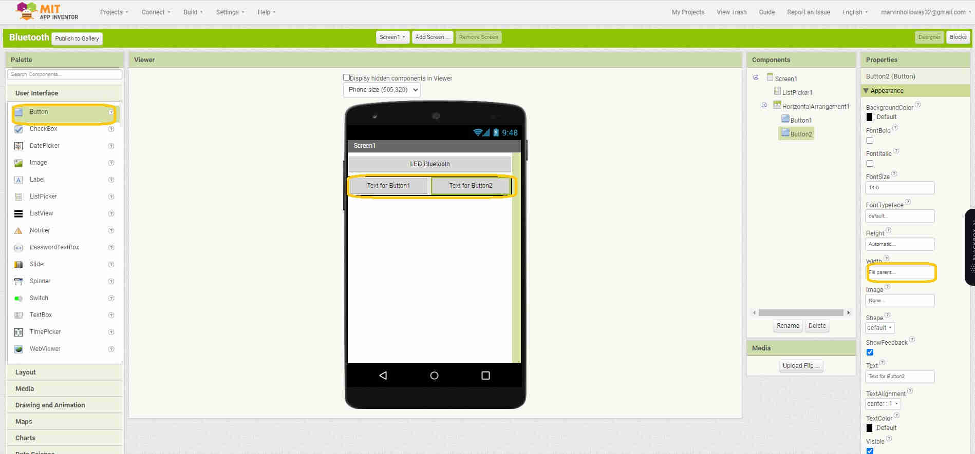
I played around a bit with modifying the color of the buttons
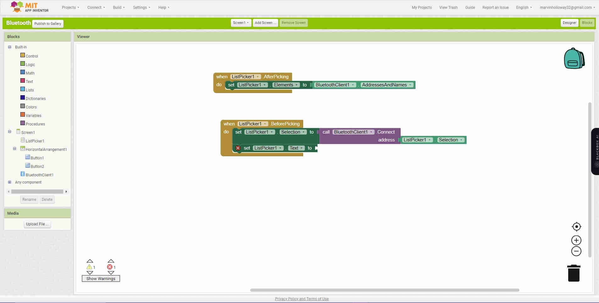
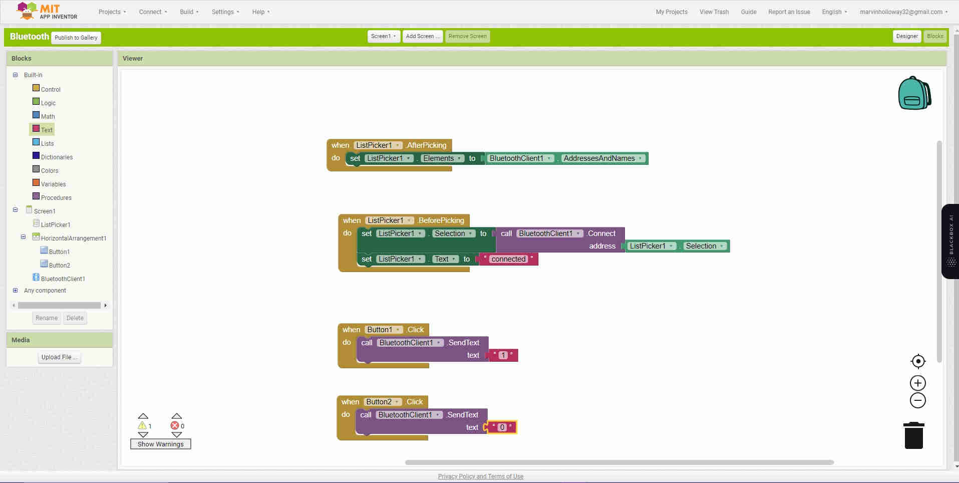
Drag and place Bluetooth Client at the base of the “phone”. Now select blocks in the tope right hand corner, the user interface will change to function block programming.
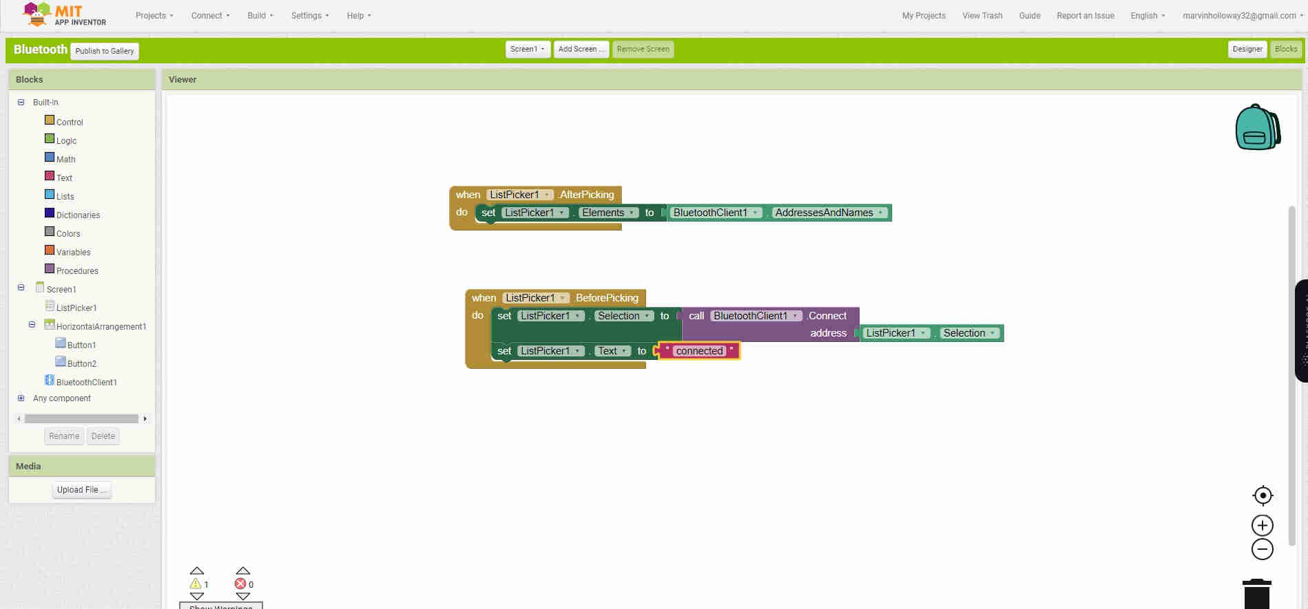
Follow the steps within the remainder of blocks withing the images below.
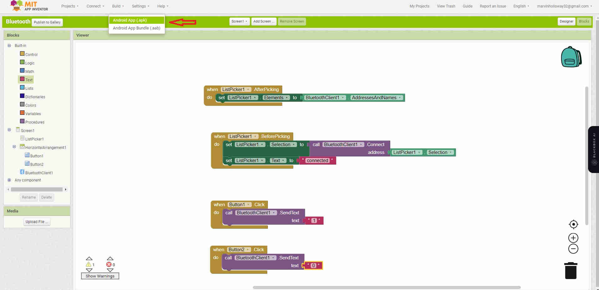
Click build, to create a QR code to aquire the APK App file that was just made
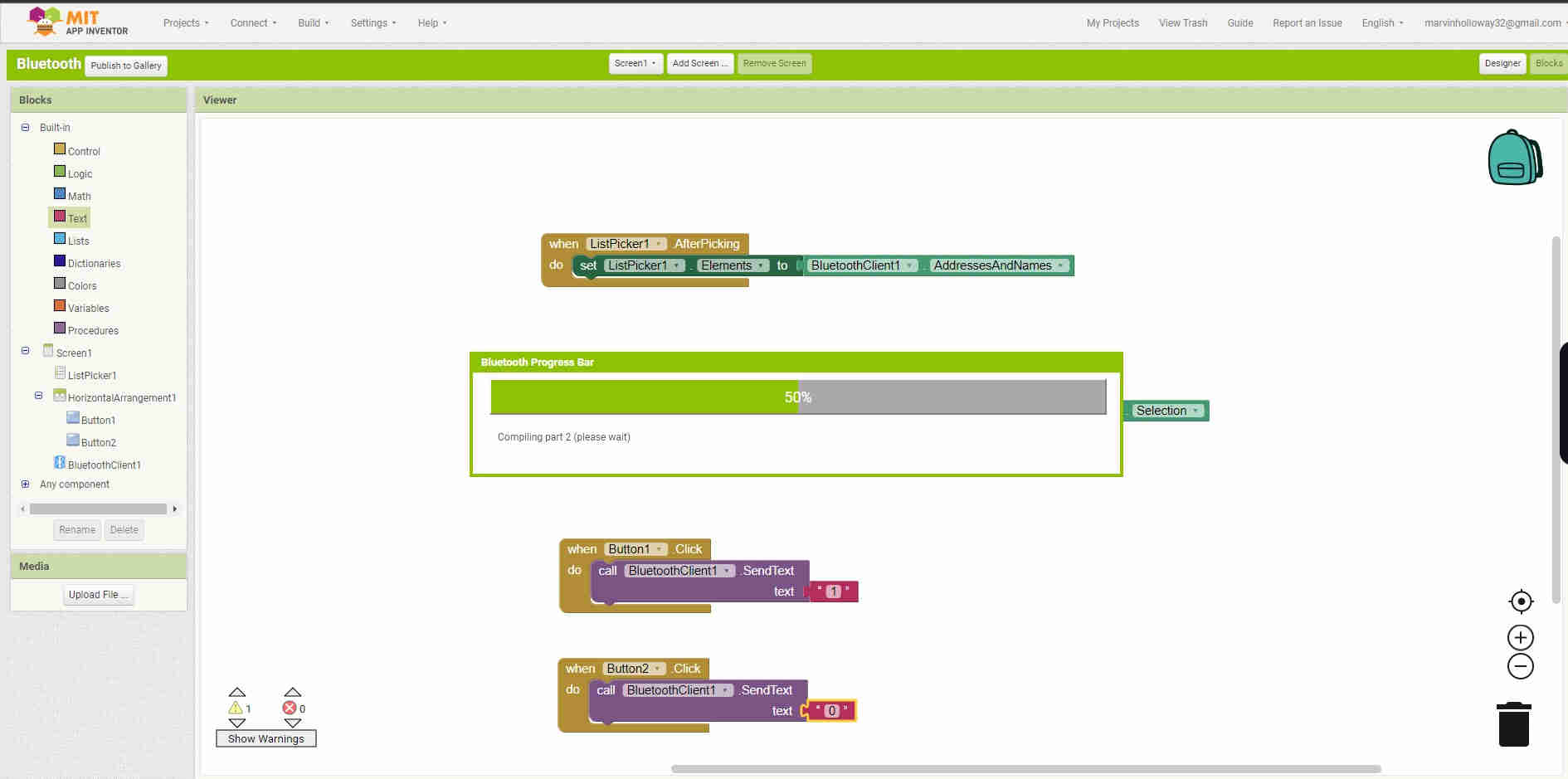
Loading…
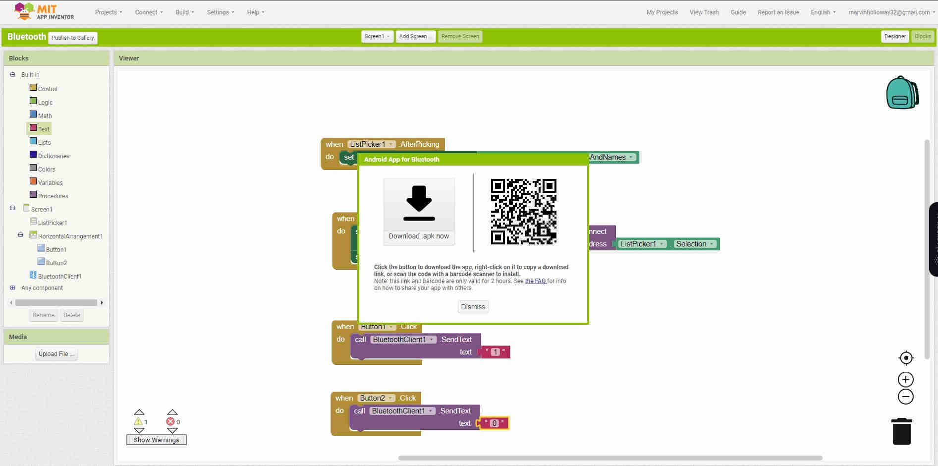
Scan the QR code to get the app
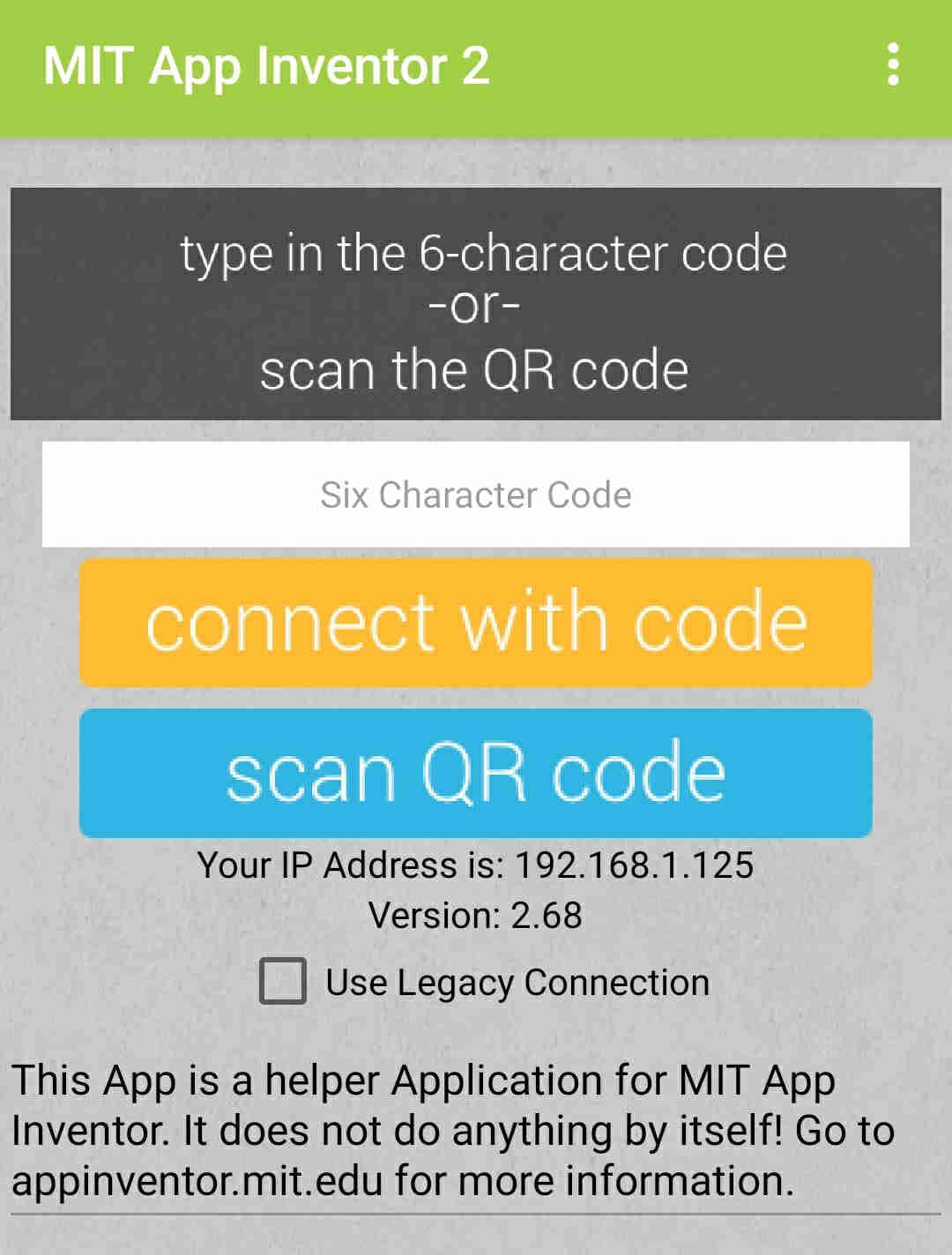
Go to the Play store and download the MIT A12 Companion app

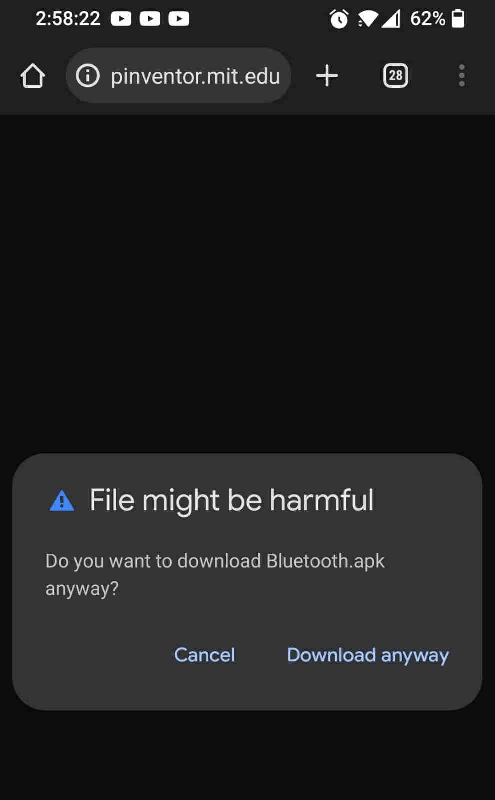
Harmful APK warning, as expected
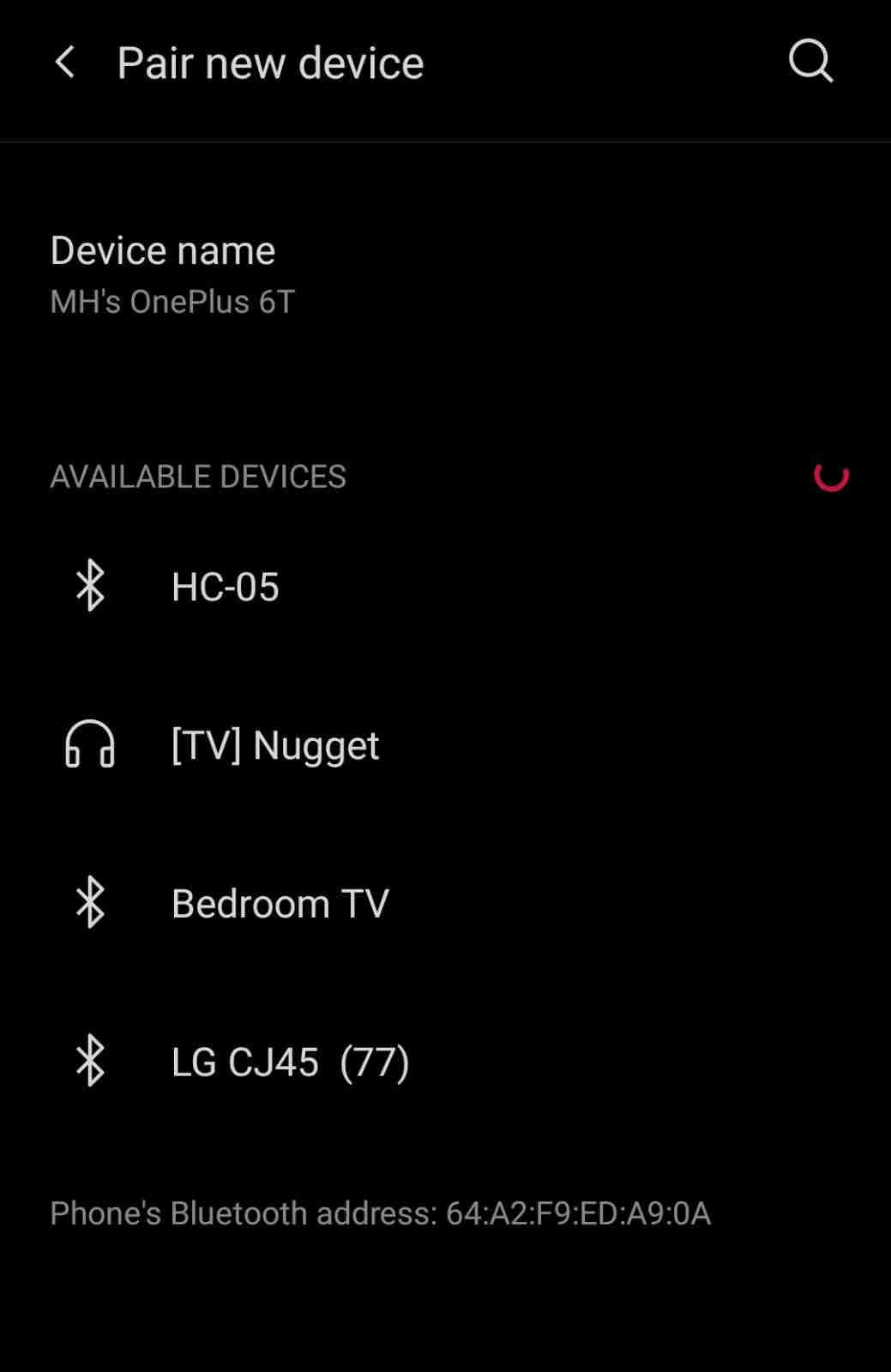
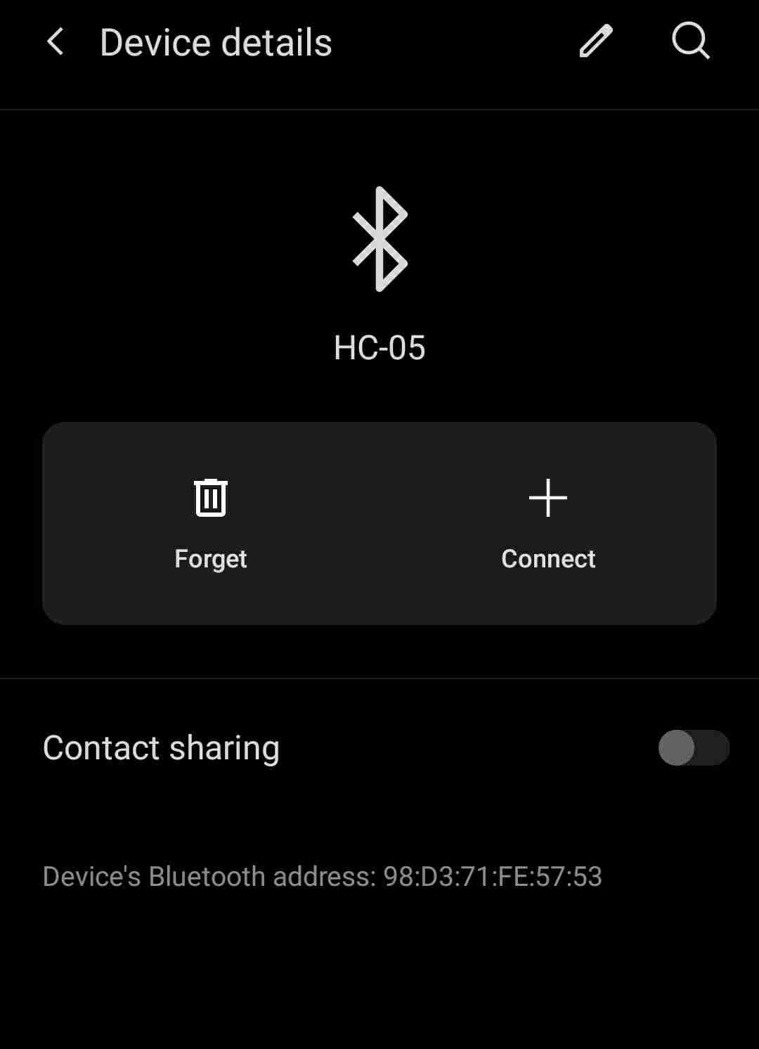
Search for HC-05 module
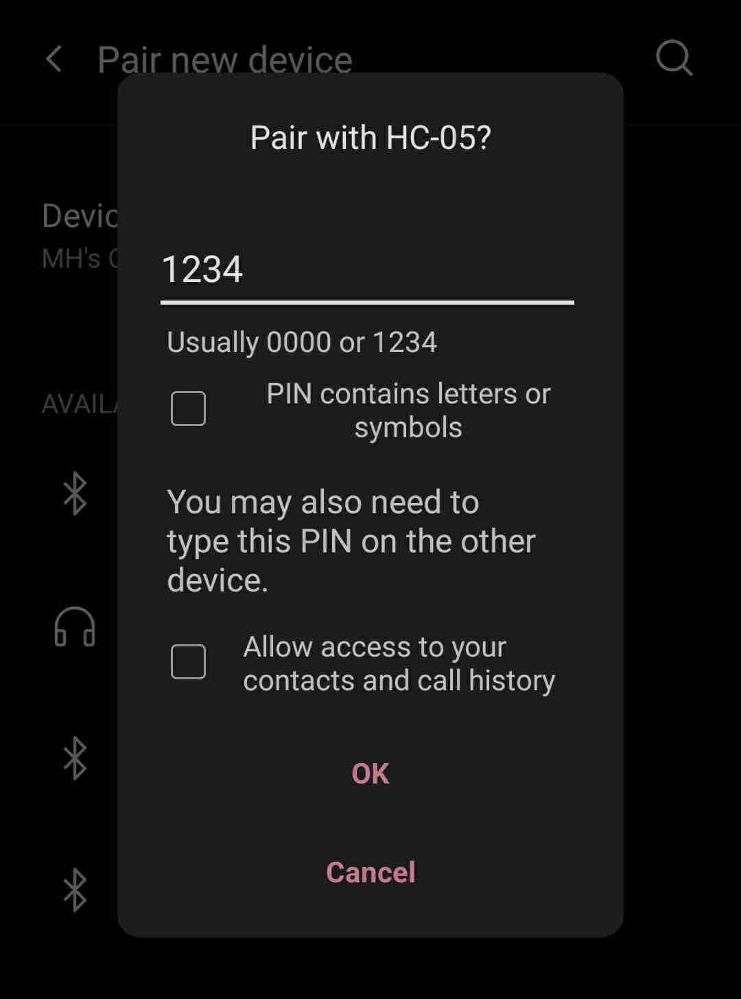
Pair with passcode as seen below
Error! Hmmm....
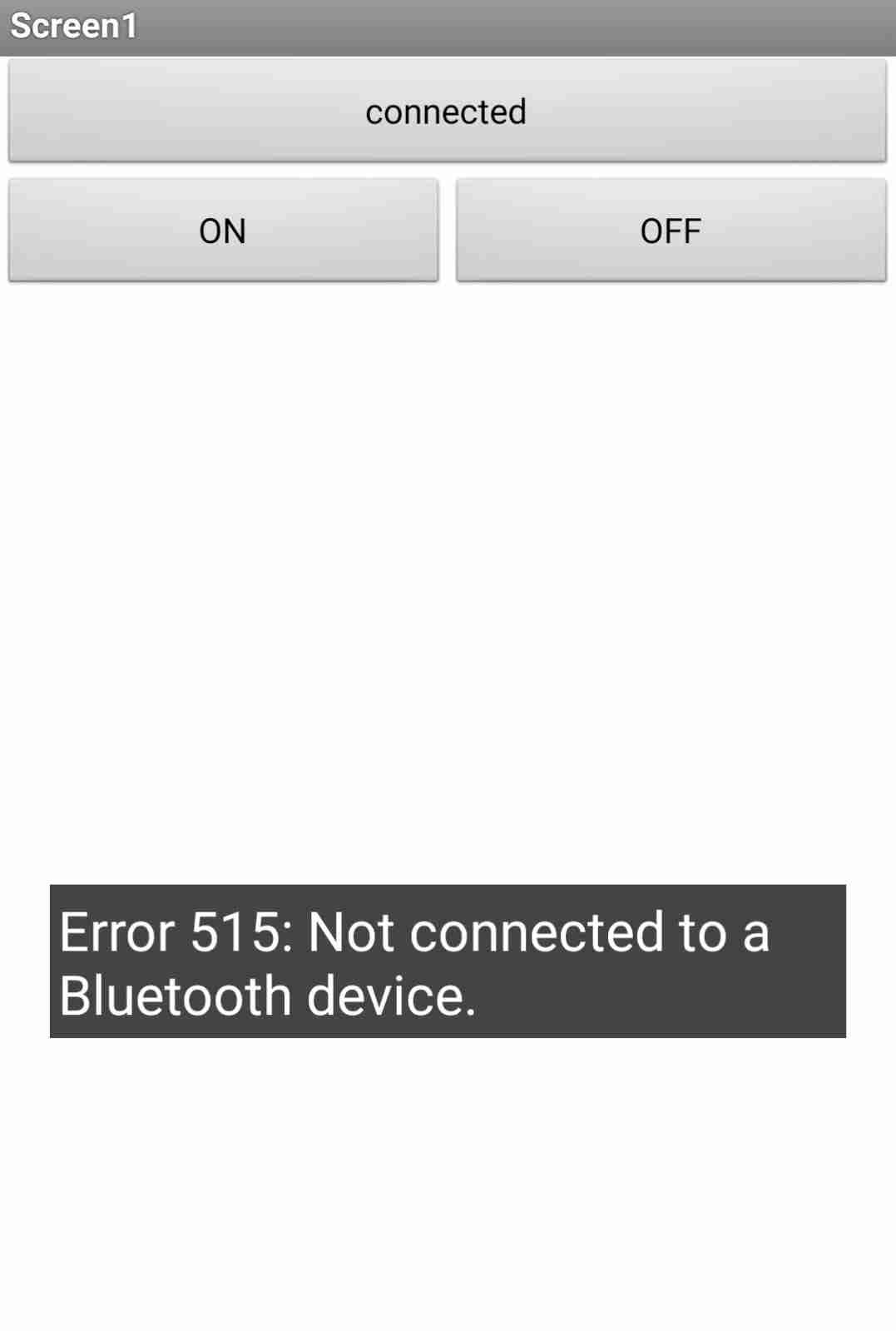
Further investigation shows that the bluetooth module never connected
I will continue further research into why the module didn’t connect.
Here are just a video of attempting to establish a connection to the HC-05 Bluetooth module. Unfortunately I was unsuccessful as mentioned earlier.
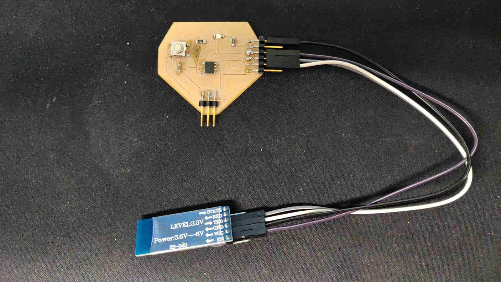
Here I have established connection betweeen my PCB and the HC-05 module.
Useful links
- The webite, app, used to create the app that was used for this assignment MIT App Inventor
From Youtube
For my code above, I sampled this you tuber’s code ( see video below), as well as wsa guided by his tutorial, very helpful.
Using Processing
Processing is a flexible software sketchbook and a language for learning how to code. It is a great tool for beginner as well as seasoned coders. I was inspired to utilise this software by one of my colleagues, Nervene. As such, I decided to do some research on the software, mainly via You Tube. I came acroos a guy by the name of Hardik Rathod, as he achieved a similar goal I had in mind. Essentially, I wanted to create an App/ GUI, that would control an LED Output within a PCB I designed and made, and instruct it to come on and off via said app.
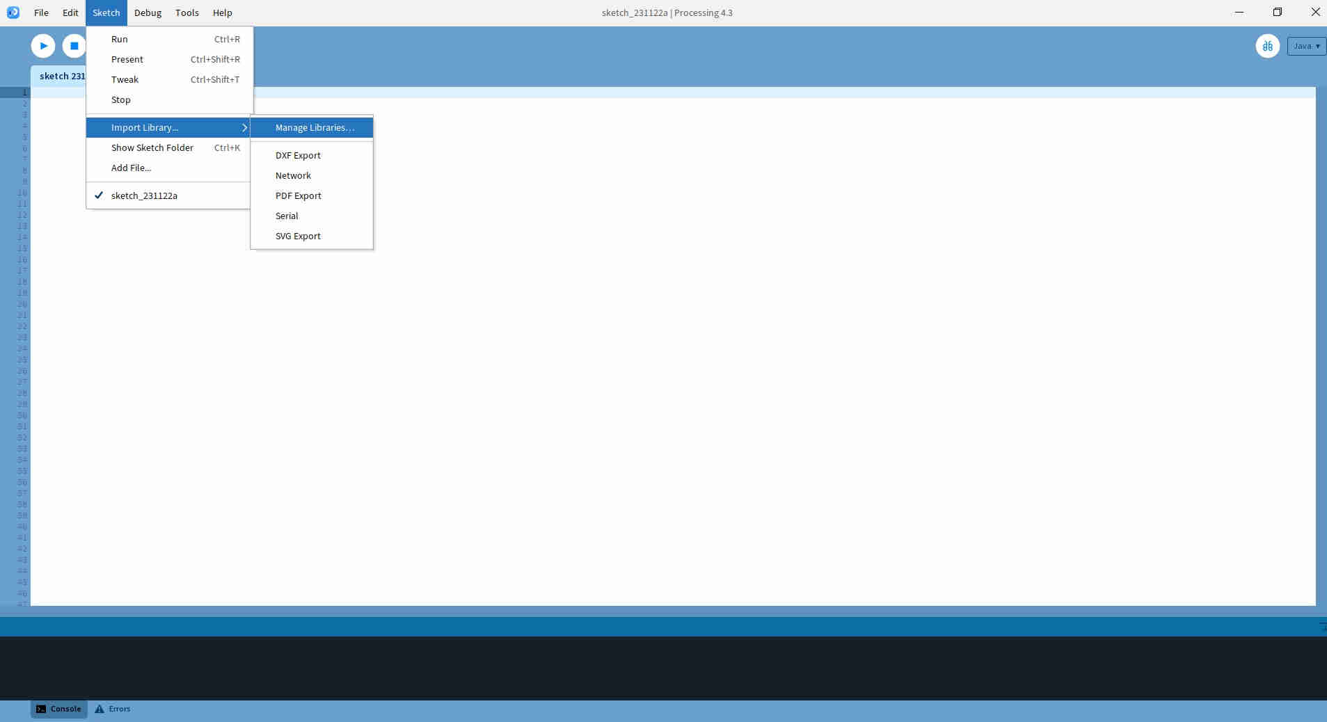
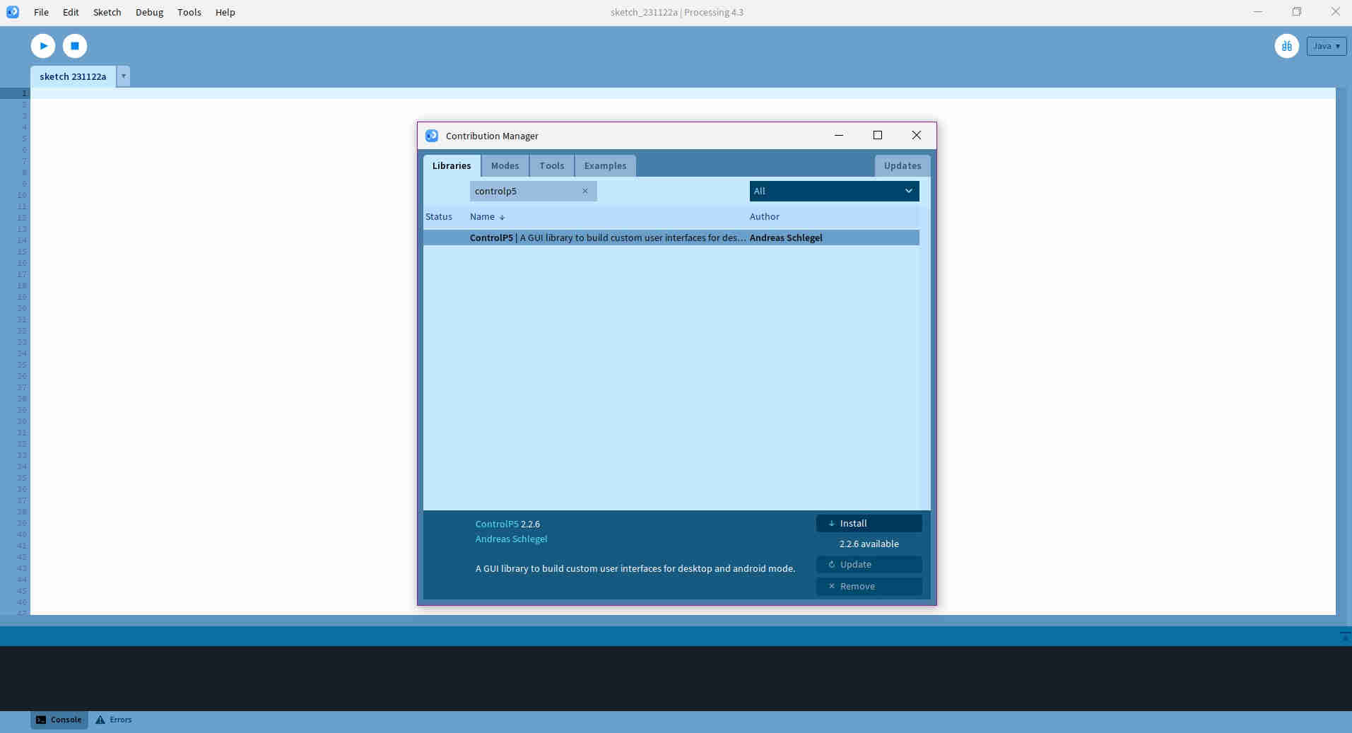
First things first, I had to import, install the Control IP5 and add it to the library within processing. This is essential, as seen in the image below, as it allowed the user to build a GUI to interface with buttons within the programs sketch.
Once this was done, my next step was to select a PCB that would be the bridge from which the Processing app and Arduino IDE programs communicate. I decided on using my “Bridge” that I used within my Networking and Communications week assignment, which utilised an ATTiny 412 chip. Next, I needed to ensure that my board was capable of sending data between the Arduino and Processing apps. To achieve this, I visited the following link and did the tutorial, verbatum.
As I was satisfied with my successfull result, I took a closeer look at Hardik’s code. His code, for both the processing and arduino IDE, basically was creating a GUI interface to light 3 LED’s, via an arduino uno. I also took a closer look at Nervene’s code, and decided to merge the both of the coding together, as they have similarities, edit and replicate it specifically for my PCB.
Processing Program/ Code
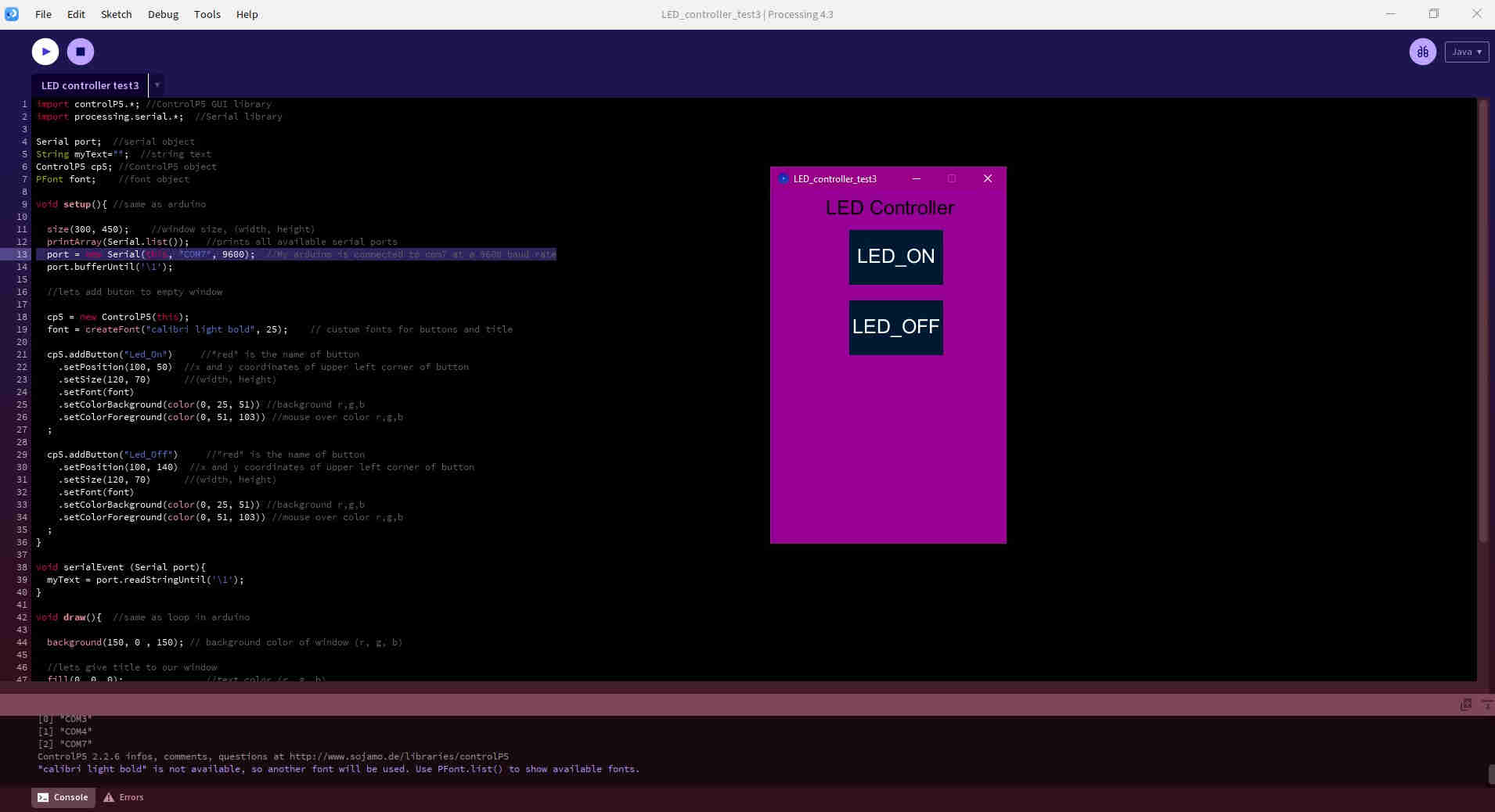
Below is the code that I would have replicated, and adapted, by way of changing essential variables specific to my PCB (writtin in JAVA):
import controlP5.*; //ControlP5 GUI library
import processing.serial.*;  //Serial library

Serial port;  //serial object
String myText="";  //string text
ControlP5 cp5; //ControlP5 object
PFont font;    //font object

void setup(){ //same as arduino

  size(300, 450);    //window size, (width, height)
  printArray(Serial.list());   //prints all available serial ports
  port = new Serial(this, "COM7", 9600);  //My arduino is connected to port com7 at a 9600 baud rate
  port.bufferUntil('\1');

  // add buton to empty window

  cp5 = new ControlP5(this);
  font = createFont("calibri light bold", 25);    // custom fonts for buttons and title

  cp5.addButton("Led_On")     //"red" is the name of button
    .setPosition(100, 50)  //x and y coordinates of upper left corner of button
    .setSize(120, 70)      //(width, height)
    .setFont(font)
    .setColorBackground(color(0, 25, 51)) //background r,g,b
    .setColorForeground(color(0, 51, 103)) //mouse over color r,g,b
  ;

  cp5.addButton("Led_Off")     //"red" is the name of button
    .setPosition(100, 140)  //x and y coordinates of upper left corner of button
    .setSize(120, 70)      //(width, height)
    .setFont(font)
    .setColorBackground(color(0, 25, 51)) //background r,g,b
    .setColorForeground(color(0, 51, 103)) //mouse over color r,g,b
  ;
}

void serialEvent (Serial port){
  myText = port.readStringUntil('\1');
}

void draw(){  //same as loop in arduino

  background(150, 0 , 150); // background color of window (r, g, b)

  //lets give title to our window
  fill(0, 0, 0);               //text color (r, g, b)
  textFont(font);
  text("LED Controller", 70, 30);  // ("text", x coordinate, y coordinat)
}

//functions to send over serial when buttons is pressed

void Led_On(){
  port.write('1');
}

void Led_Off(){
  port.write('0');
}
Note Determining the COM port is very important as this is where the data would transfer would occur from the Arduino code to work with the Processing Code/ interface.
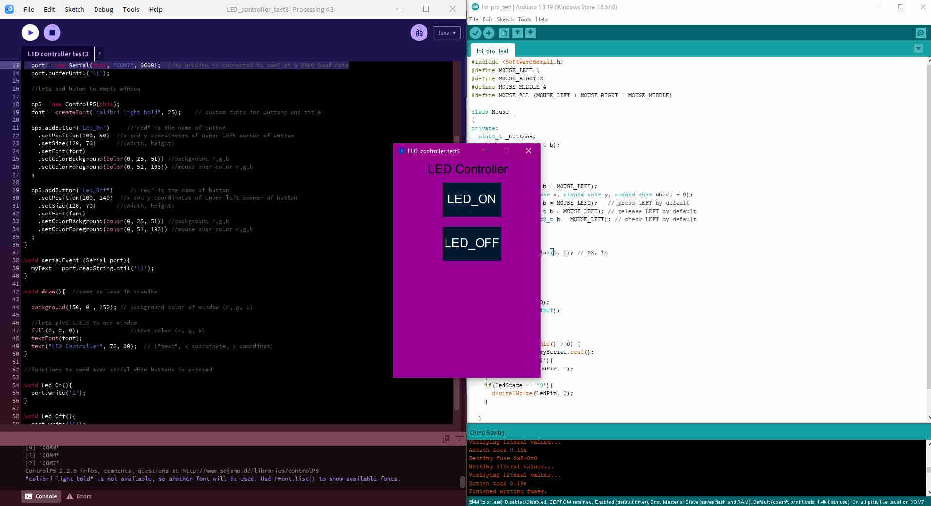
The above code would produce the GUI interface, as seen within the image below. Each lines comments gives a better detailed description of what the code is doing.
Arduino Code
Similarly to the processing code/ sketch, I replicated and adapted “Nervene’s code”, by changing specific variables, which he also replicated and adpated from Z-HUT, to suit my “Bridge” PCB I was using to accomplish the assignment, as seen below
#include <SoftwareSerial.h>
#define MOUSE_LEFT 1
#define MOUSE_RIGHT 2
#define MOUSE_MIDDLE 4
#define MOUSE_ALL (MOUSE_LEFT | MOUSE_RIGHT | MOUSE_MIDDLE)

class Mouse_
{
private:
  uint8_t _buttons;
  void buttons(uint8_t b);
public:
  Mouse_(void);
  void begin(void);
  void end(void);
  void click(uint8_t b = MOUSE_LEFT);
  void move(signed char x, signed char y, signed char wheel = 0);
  void press(uint8_t b = MOUSE_LEFT);   // press LEFT by default
  void release(uint8_t b = MOUSE_LEFT); // release LEFT by default
  bool isPressed(uint8_t b = MOUSE_LEFT); // check LEFT by default
};
extern Mouse_ Mouse;

SoftwareSerial mySerial(0, 1); // RX, TX

int ledPin = 4;  // The LED output pin

void setup()
{
  mySerial.begin(9600);  // same baudrate as the processing app
  pinMode(ledPin, OUTPUT);
}
void loop()
{
  if(mySerial.available() > 0) {
    char ledState = mySerial.read();
    if(ledState == '1'){
      digitalWrite(ledPin, 1); // Turn LED On
    }
    if(ledState == '0'){
      digitalWrite(ledPin, 0);  // Turn LED off
    }

  }

}
Connection and Execution
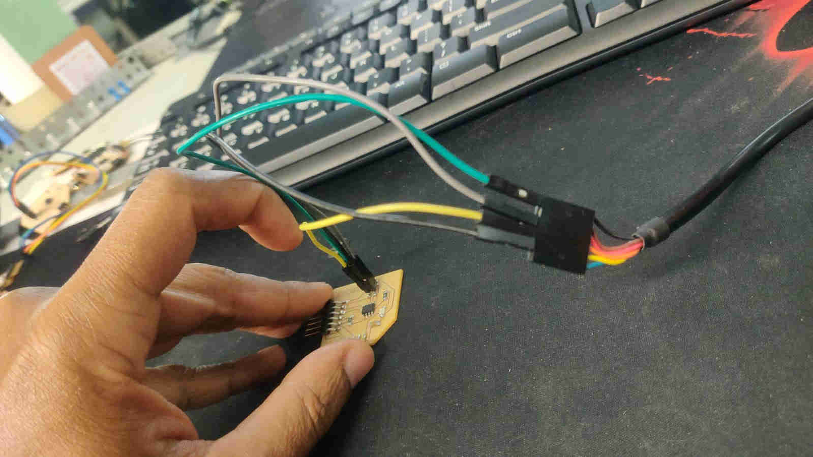
For downloading the Arduino code onto my PCB, I connected the FTDI cable to the UPDI pins of the board, uploaded the code, ensuring that the correct PIN was identified for the LED, in my case PIN 4, as well as the RX and TX pins were allocated as 0, 1 respectively.
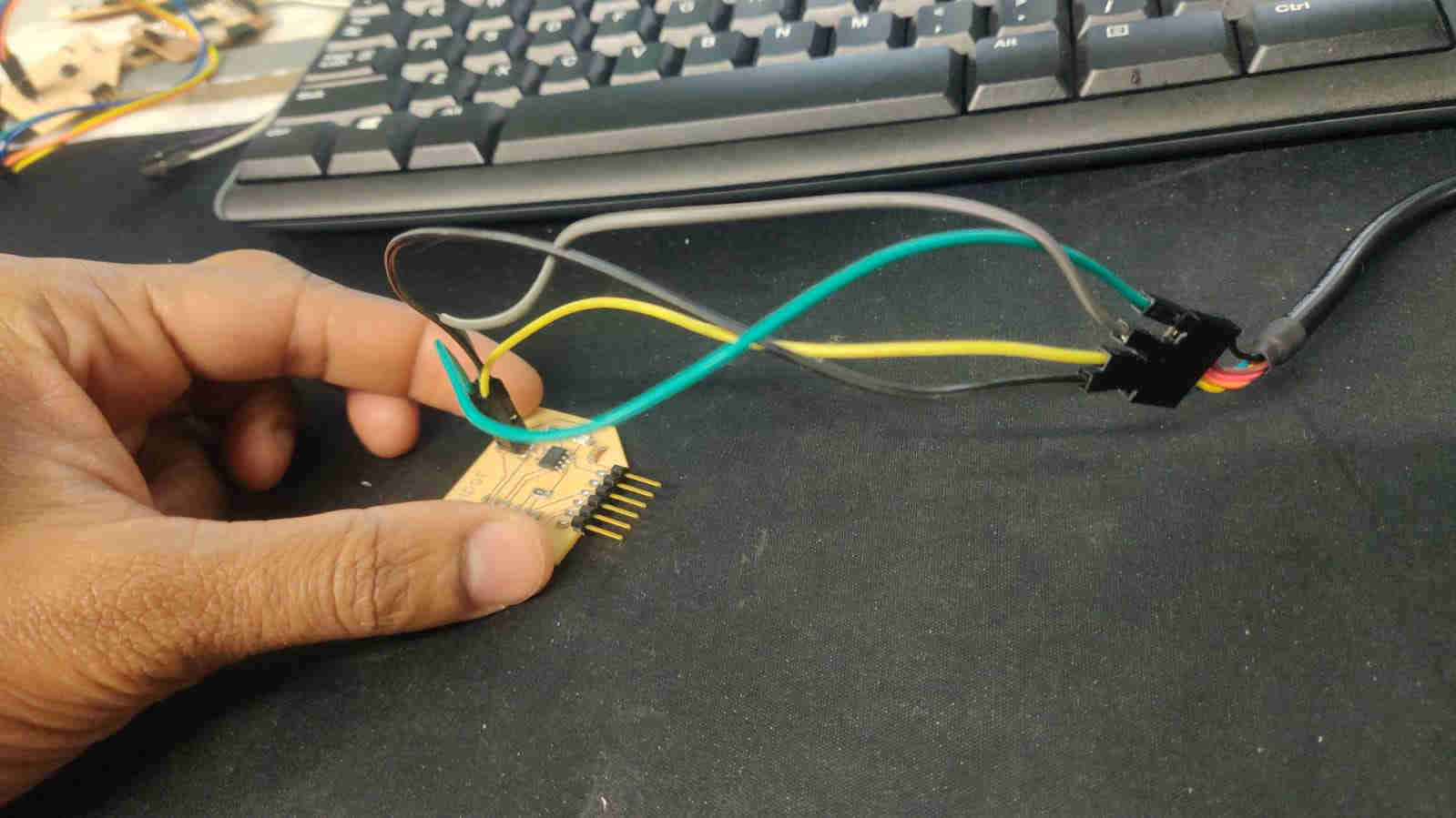
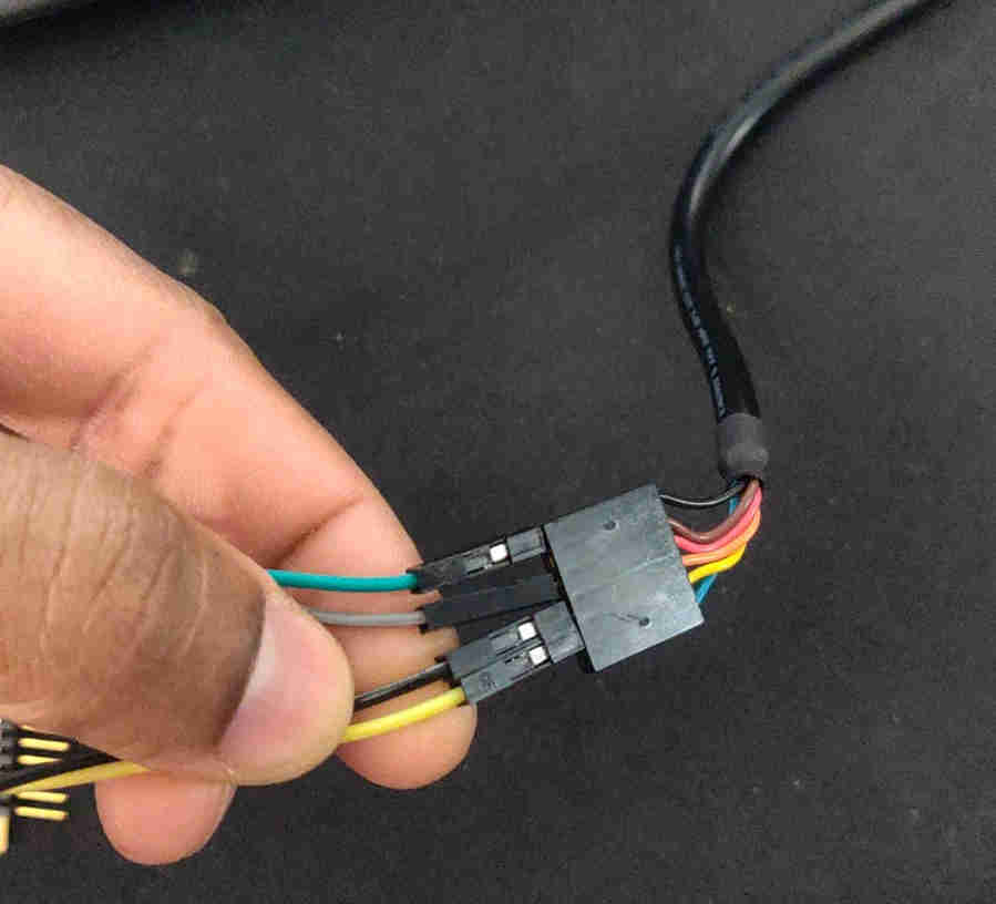
Once the arduino code was uploaded sucessfully, I made sure that the FDTI’s and the serial cable’s connection wereas follows
- Serial VCC -> FTDI VCC
- Serial GND -> FTDI GND
- Serial RXD -> FTDI TXD
- Serial TXD -> FTDI RXD
Now that that was sorted, it was time to test the code/ interface