21. Output Devices Group
This week I worked on defining my final project idea and started to getting used to the documentation process.
Assignment
Individual assignment:
  add an output device to a microcontroller board you've designed,
     and program it to do something
Group assignment:
measure the power consumption of an output device
GROUP ASSIGNMENT
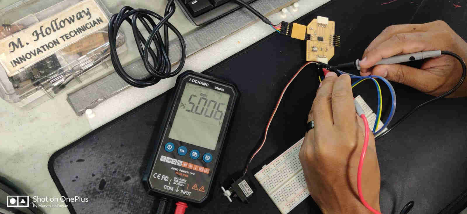
For the Group Assignment for the Output Devices assignment, we were tasked with measuring the POWER consumption of an Output Device. For this, we utilized Marvin Holloway’s “Hollowino” PCB. This is the very same PCB that he connected his servo to for his individual assignment for his output device week assignment. To determine the power consumption of the above-mentioned servo, we connected the Hollowino board, with the servo (output device), to a breadboard. This was done to provide us with easier maneuverability when testing using the multimeter leads.
Firstly, we tested the output voltage supplied to the servo. Even though we know it is 5 Volts, we still did this as a precaution, (as seen in the image).
Once we were satisfied with our tested results, we then proceeded to measure the current (amperage), of both the VCC from the PCB (Hollowino) and the VCC connected to the servo, as seen in the successive images listed below.
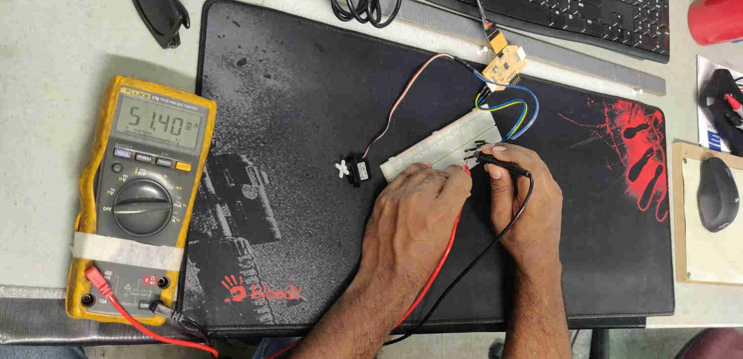
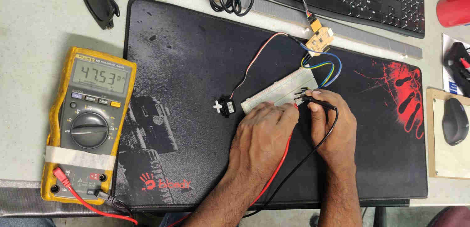
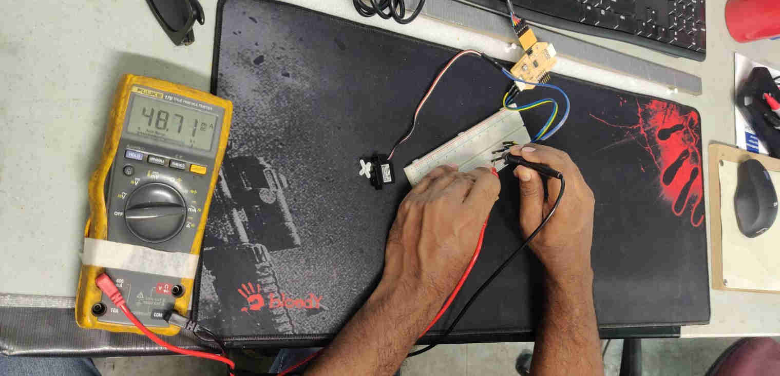
As seen on the Multimeter’s display screen, we got an amperage, which was measured in milliamps, ranging between 47.5, 48.7 and 51.4 mA, with a maximum of 65.3 mA (not seen in images).
Now that we have these two known values, that is, our voltage of 5 Volts, as well as, our current of 65.3 mA, we can determine the power consumption, by using the formula;
P=VI
- P (Power),
- V(voltage)
- I(amperage)
By plugging in our values into the formula, we get; P= 5 x 0.065 (65.3 mA = 0.065 A)
P= 0.325 W (W=Watts)
Therefore, we can safely say that the power consumed by the servo is 0.325 Watts.