2. Computer Aided design
CAD 2D and 3D Design
Learning objectives
• Evaluate 2D and 3D modelling software • Describe and detail the modelling process, utilising the CAD software used.
Project Application For my project, I’m required to innovate on an existing key tool that’s used with most if not all FABLABs, a desktop vice. My method of doing this was to automate it. The process of doing this involves attaching a somewhat simple electronic system, that moves an adapted “gear track”, that’s powered via a controlled high motor, with a momentary switch utilising a reverse polarity concept. My initial thought was to redesign an entire vice, but as it’s already being adapted to an existing vice, I decided to focus on designing the mechanism instead.
The Mechanism
To design the mechanism, I did some research into what would be the ideal design for this application. I came to the conclusion of creating a simple rack and pinion to be the driving force behind my design. To do this, I utilised Fusion 360 and TinkerCAD. This is a tentative design, as I progress, the moving mechanism may swap the rack for a spiral gear, for greater stability.
Suggested Software
Below are a list of software that was suggested by our lecturer for this week’s assignment, and my personal experience testing/ evaluating them;
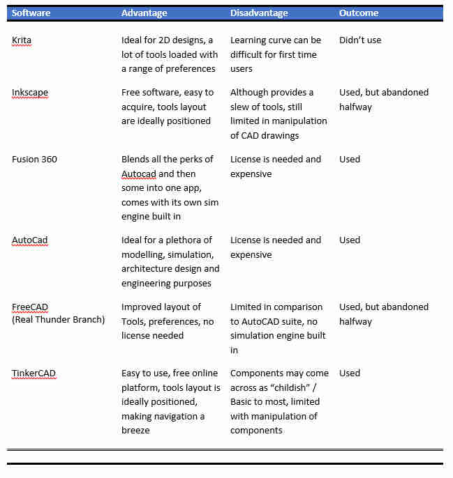
2D Drawing of Gear
I designed my gear using Autocad. I attempted to use a range of the software that was recommended, inclusive of Inkscape, but found the learning curve to be challenging, as such, I settled on Autocad. Below, are just a few steps to designing the gear in 2D;
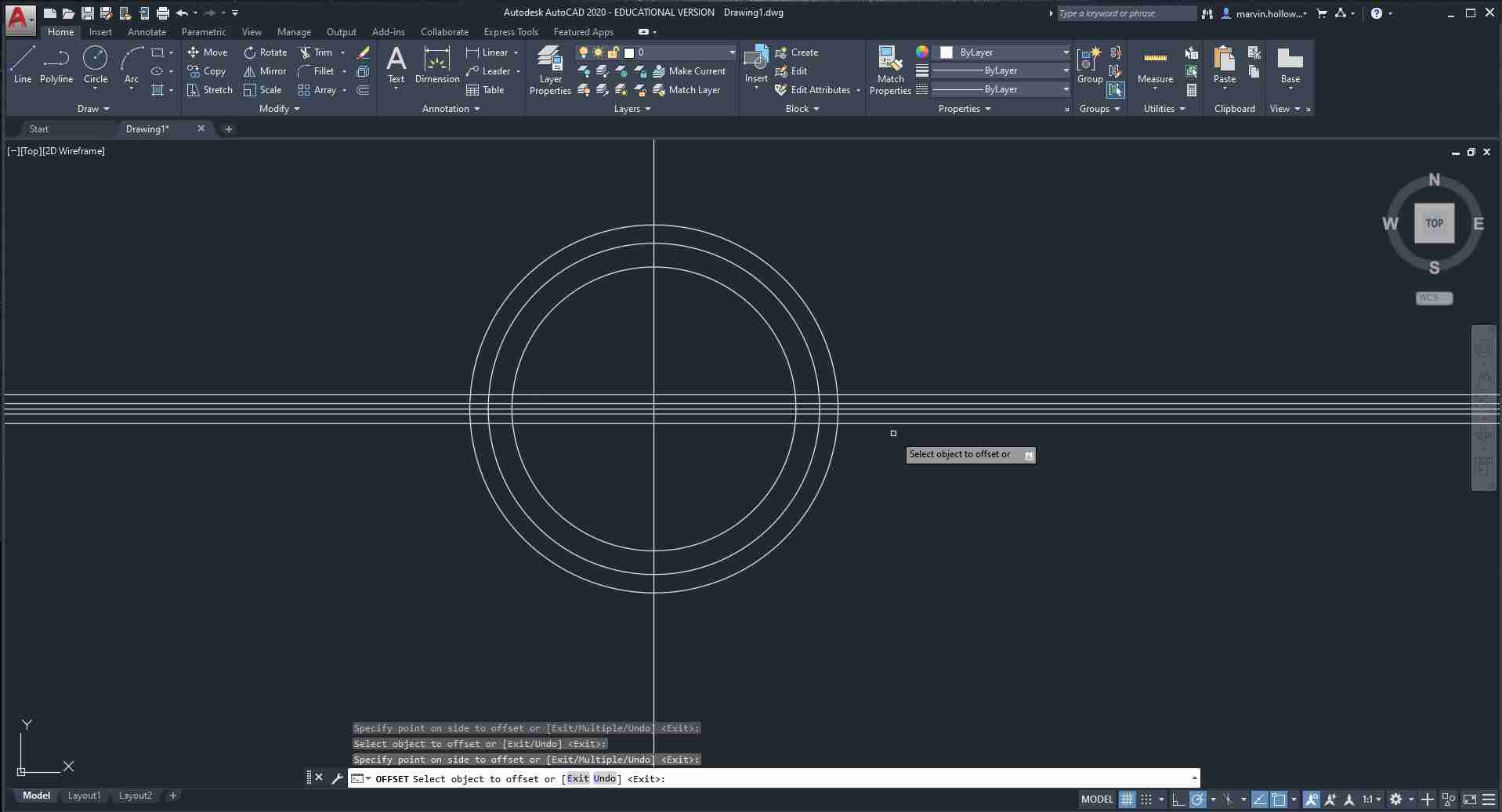 I used construction lines as a guide to ensure precise dimensioning (even though I did not include dimensions)
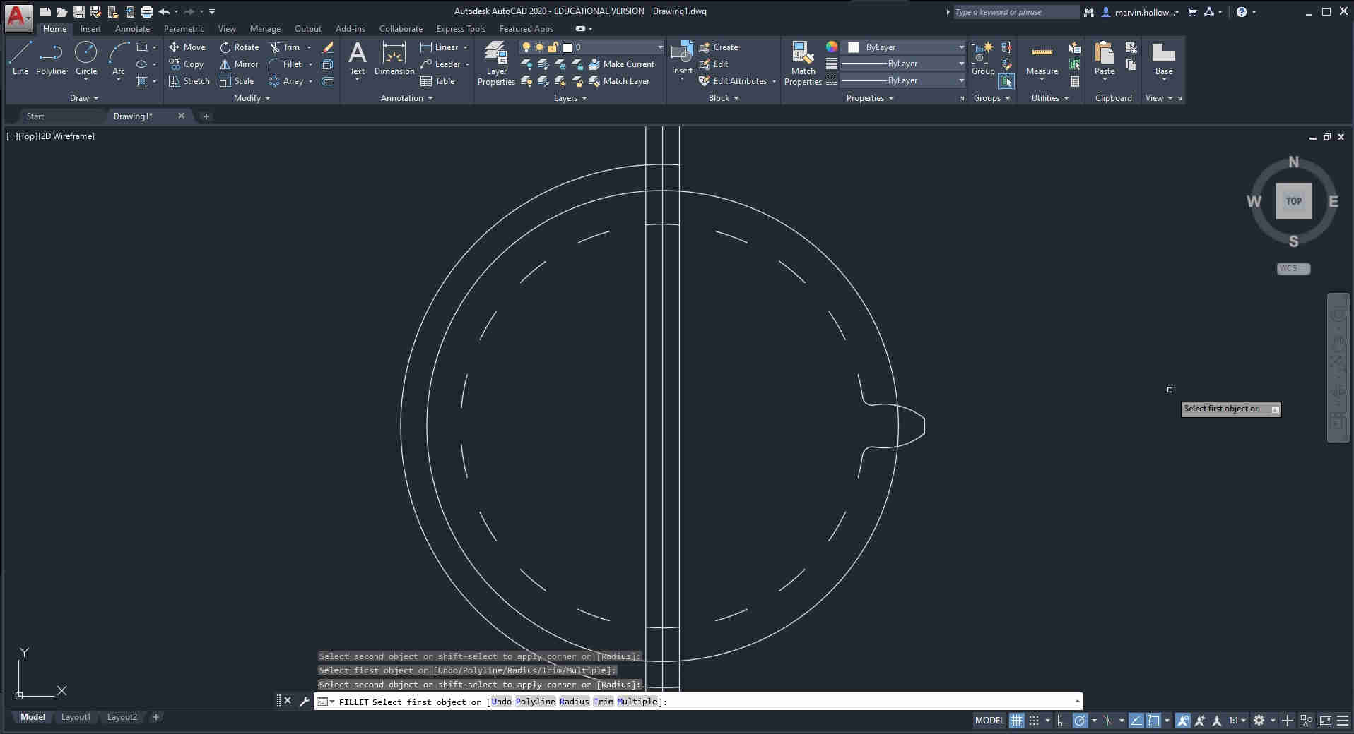 At this stage, I generated a single tooth, then I used the polar array feature, see next pic.
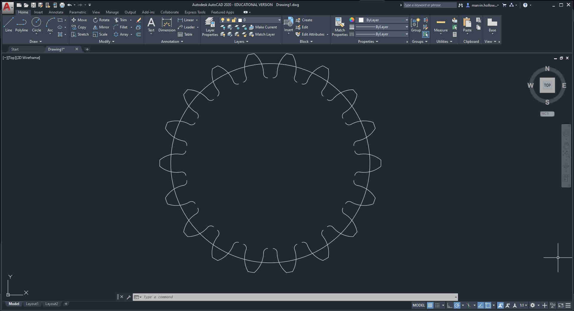 The teeth are equally distributed, and the overall design of the gear is coming to fruition
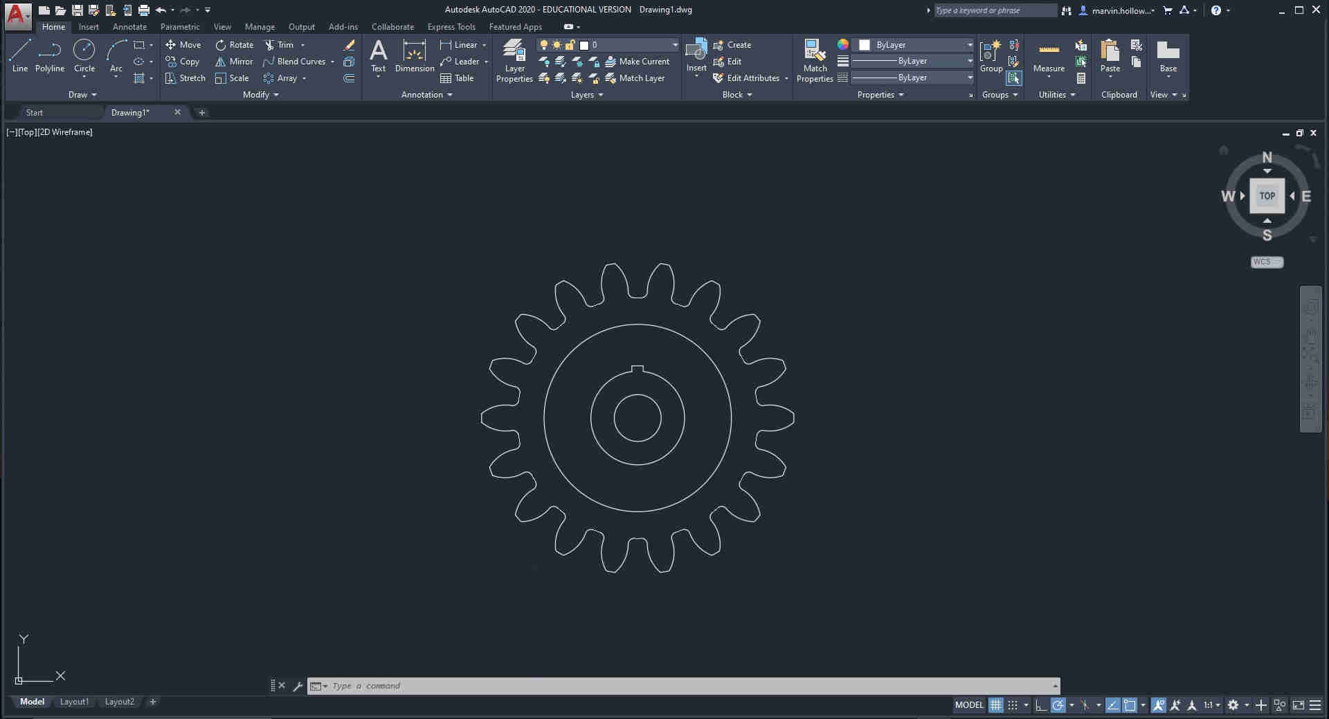 Here is the final design, unfortunately, I was not able to design the rack in Autocad. I decided to create it within the 3D drawing instead, which is currently, under construction
2D Drawing Design File Gear
3D Drawing of Design
I attempted, tested and evaluated a range of different 3D Design apps, inclusive of, Fusion 360, FreeCAD (Real Thunder) and Tinkercad. Both the FreeCAD and Fusion posed to be quite time consuming and challenging to use for me, mostly because I am not the best CAD user, if I’m being honest. Maybe it can be attributed to the layout of tools, comprehension of said tools and just the general GUI. As I have a greater familiarity with Tinkercad, as I utilise it to conduct workshops within (NIHERST), the organisation I work for, this was ideal for me to use to generate a “rough draft” of the moving mechanism I intend to use for my final project.
Below, is a screenshot of my design done within Tinkercad
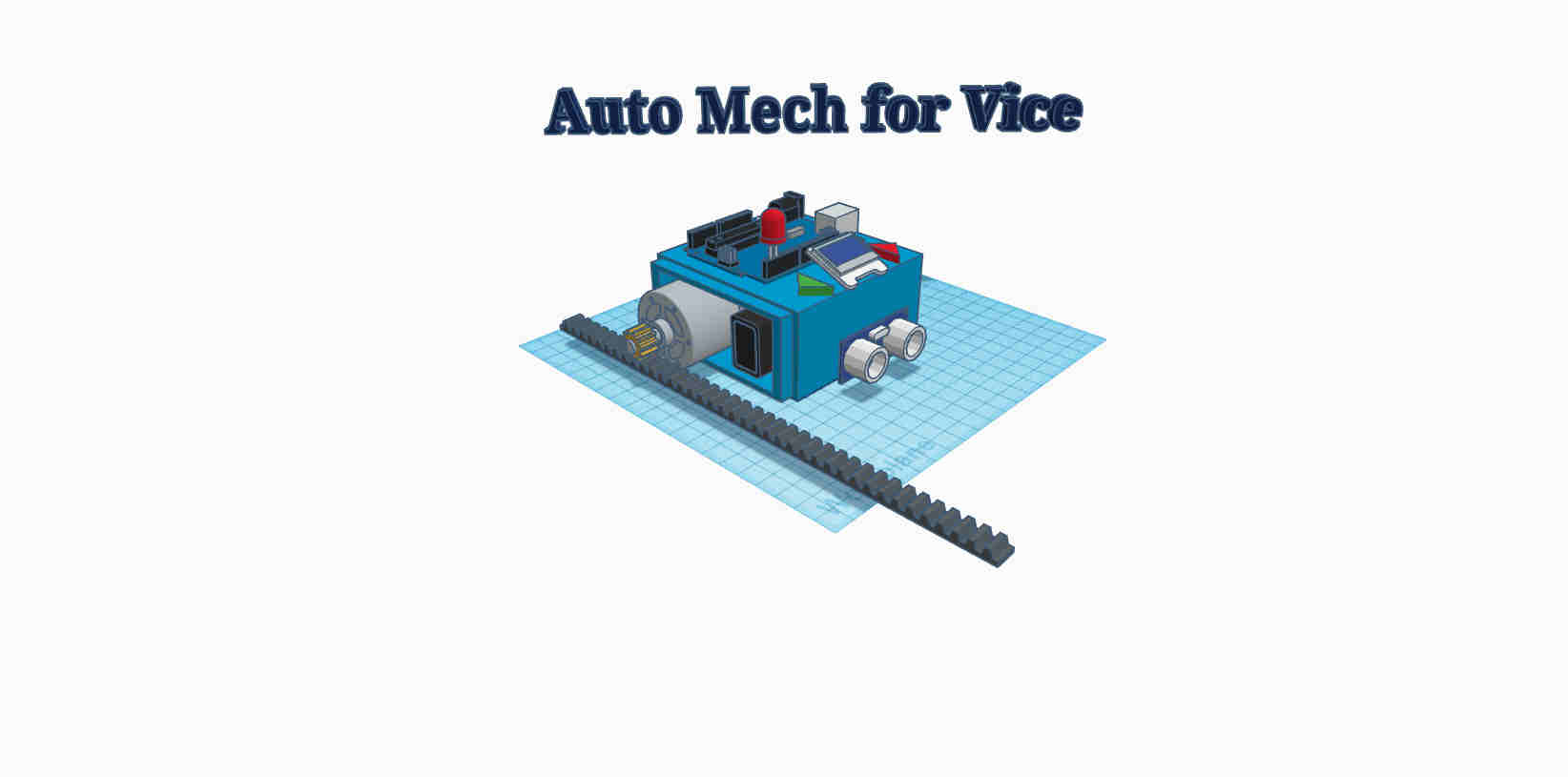
It may not look like much, and I must mention that a couple components can be swapped out, or left out all together as the design process progresses, but this is ideally the rough concept of what the moving mechanism should entail.
3D Design File Mechanism
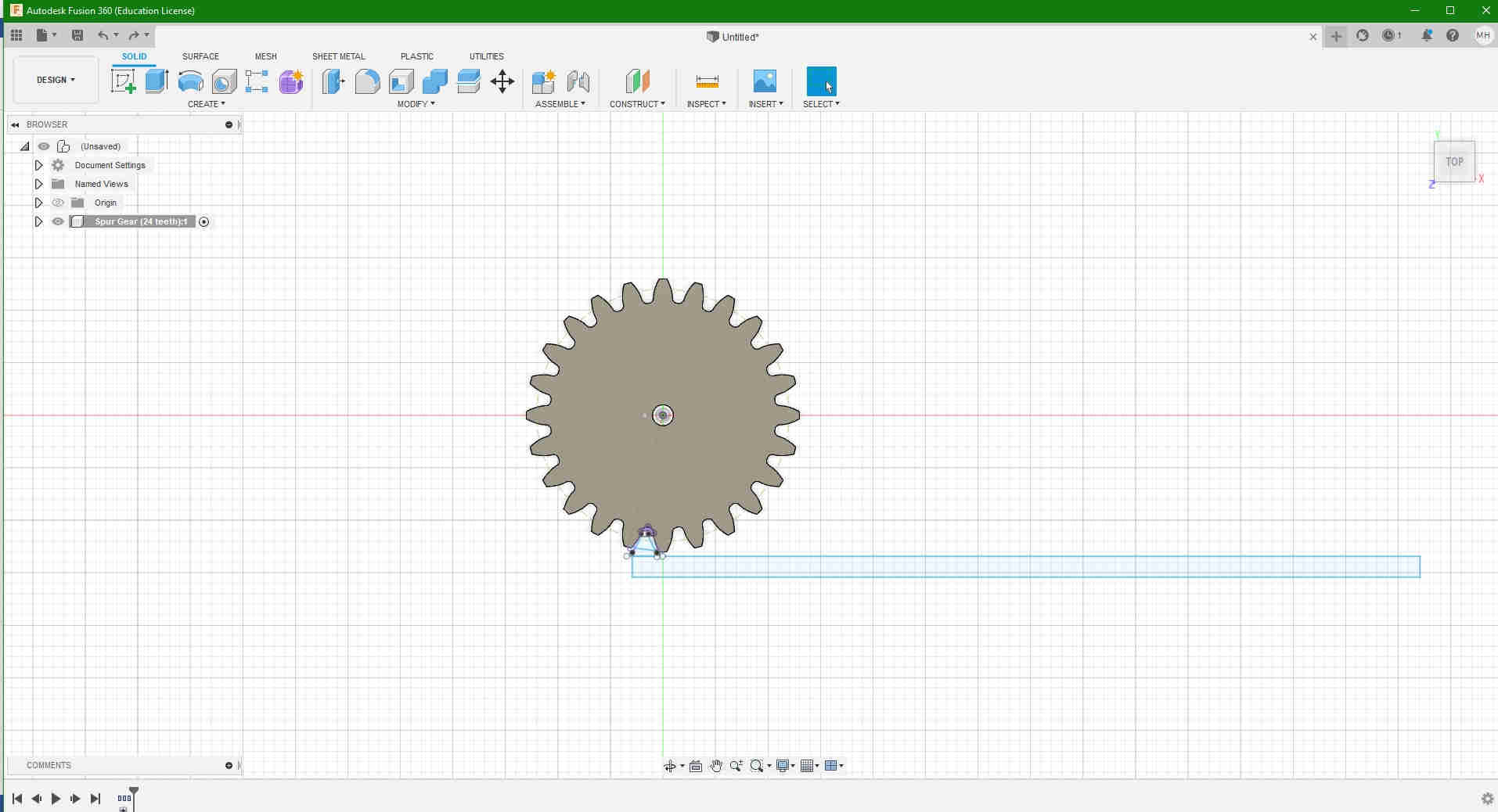
3D with Fusion 360
Also worth mentioning, I started designing the moving rack and pinion within Fusion 360, but was unable to complete, and simulate it. I do intend at a later date to finish this, and upload it to my website. In the interim, below is just a sneak peek of what I have thus far