9. Output devices
This week I worked on my Output Devices assignment.
Individual assignment: add an output device to a microcontroller board you’ve designed, and program it to do something
Group assignment: measure the power consumption of an output device
Individual Assignment/ Process
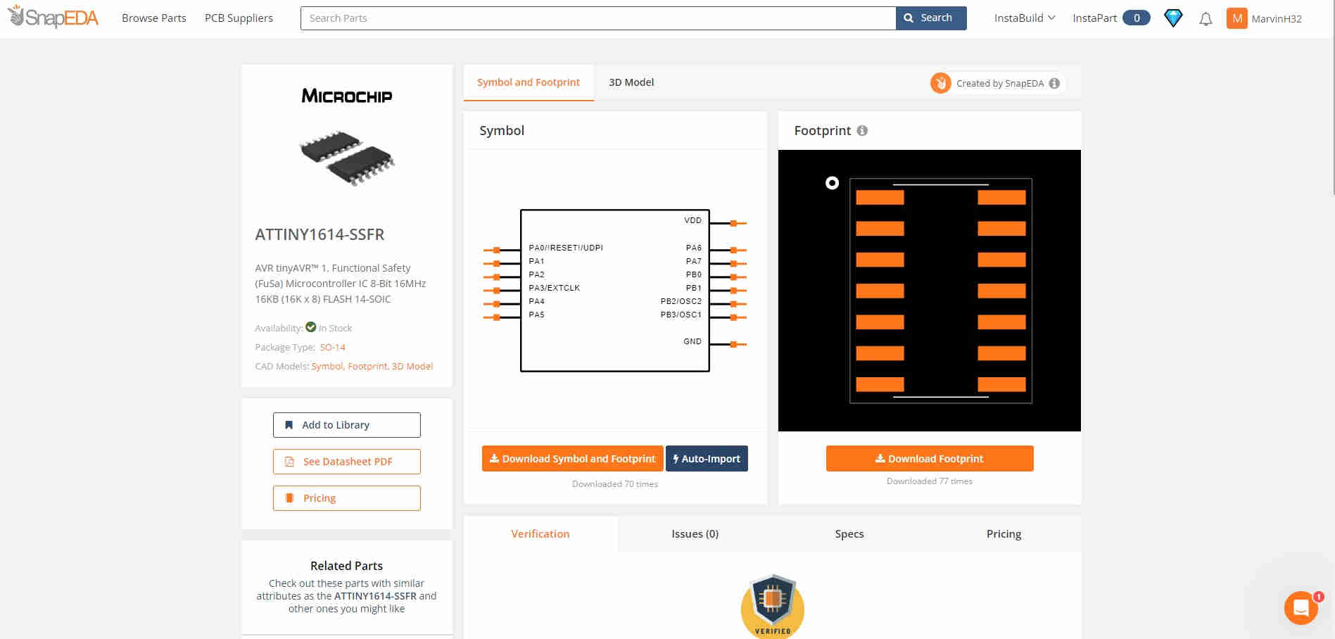
For my individual assignment, I decided on using a new microchip, the ATTiny 1614. in addition to this, I decided to utilise this opportunity to design, mill and solder my PCB, that would in fact be used within my Final Project. As expected, I used Fusion 360 to design my board. Firstly, I had to head over to Snap EDA and import a foot print for the desired chip, the ATTiny 1614, as seen in the image below:
Upon doing this, I designed my circuit similarly to the previous, in the sense that I utilised the same components save and except the microchip. This was done using the Fusion 360 Software in tandem with the Eagle Library. Feeling a bit more creative than ususal, I designated the name “Hollowino” to this PCB, and yes it’s an amalgmation of my title and an Arduino. The decision to use this chip, was to allow me the opportunity to experiment with a new chip as well as providing my chip to posess a greater number of I/O’s.
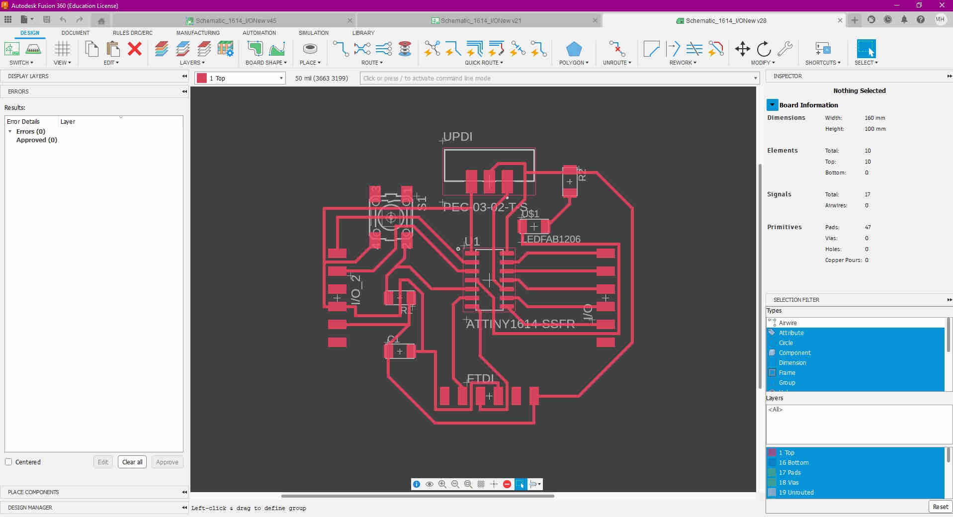
The above image shows aspects of the designing process for the Hollowino, done using Fusion 360, schematic etc.
PCB Production
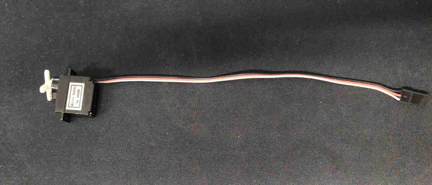
Using carbide create and carbide motion, I milled my PCB “Hollowino”, (see image), and proceeded to solder my components to my board, (see short youtube video below). The output device I incorporated was a simple Micro Servo. This micro servo has the capability to rotate from a 0-180 degree range and requires low power, making it an ideal candidate for this assignment. An “X Clutch” was used to provide a “visual” rotation when programmed. As with most servos, this micro servo has three wired connections, one is allocated to the Signal, VCC and the Ground, (see image).
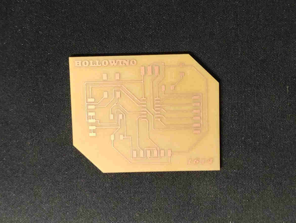
Soldering the “Hollowino”
The Micro Servo
PCB Programming
For the programming aspect of the assignment, I used the Arduino IDE software to accomplish this. Within the software/ App, there are sample/ example codes that allow the user to be able to program a plethora of devices,whether it be I/O, LCD Displays or even simple arduino circuits, etc. as seen in the image below:
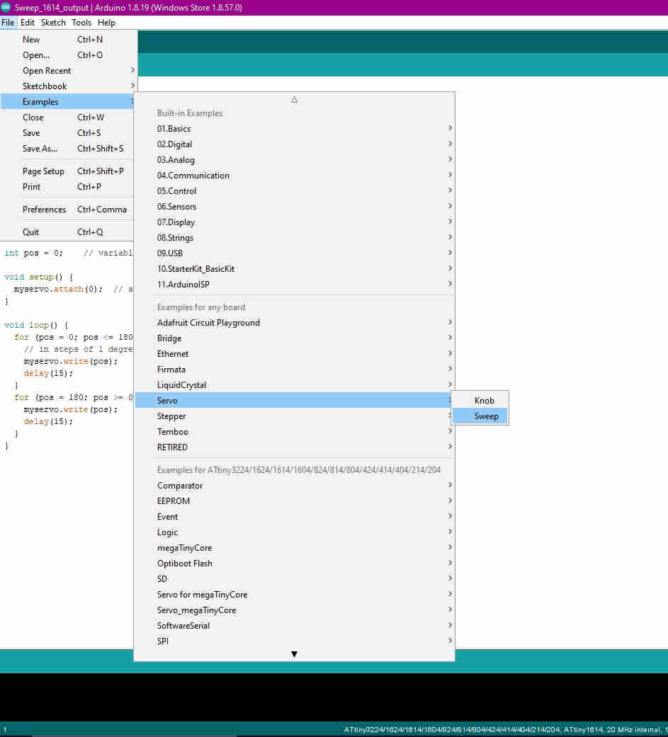
The example code proved ideal for my mirco servo. The servo library, built into the Arduino IDE, must first be declared within the programming, to ensure the servo functions as desired.
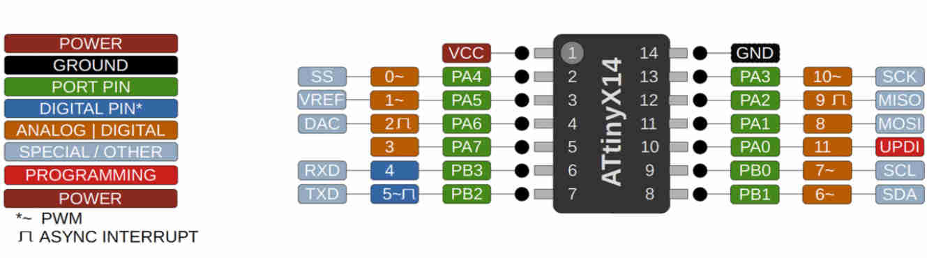
I then changed the signal pin (white cord/pin/ wire on the servo), within the code (seen below in CODE) to correspond with the digital/ analog pin on the chip (ATTiny 1614),to pin 0. I used the pinout (see image below) for the ATTiny 1614 chip as a guide to determine this.
ATTiny 1614 Pinout
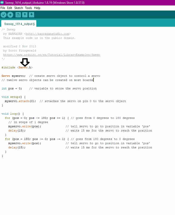
CODE
/* Sweep
 by BARRAGAN <http://barraganstudio.com>
 This example code is in the public domain.

 modified 8 Nov 2013
 by Scott Fitzgerald
 https://www.arduino.cc/en/Tutorial/LibraryExamples/Sweep
*/

#include <Servo.h>

Servo myservo;  // create servo object to control a servo
// twelve servo objects can be created on most boards

int pos = 0;    // variable to store the servo position

void setup() {
  myservo.attach(0);  // attaches the servo on pin 0 to the servo object
}

void loop() {
  for (pos = 0; pos <= 180; pos += 1) { // goes from 0 degrees to 180 degrees
    // in steps of 1 degree
    myservo.write(pos);              // tell servo to go to position in variable 'pos'
    delay(15);                       // waits 15 ms for the servo to reach the position
  }
  for (pos = 180; pos >= 0; pos -= 1) { // goes from 180 degrees to 0 degrees
    myservo.write(pos);              // tell servo to go to position in variable 'pos'
    delay(15);                       // waits 15 ms for the servo to reach the position
  }
}
In the video below, we can see the final results. The code was executed as expected with the servo, to my satisfactory standards.The servo is programmed to move from 0 degrees to 180 degrees and then back again, on repeat/ loop.