4. Embedded programming
Individual assignment:
  browse through the data sheet for your microcontroller
  write program for a microcontroller development board
  to interact (with local input &/or output) and communicate (remotely)
  extra credit: use different languages &/or development environments
  extra credit: connect external components to the board
Group assignment:
compare the performance and development workflows for other architectures
Individual Assignment
Reading the DATA Sheet
ATTiny412
The data sheet for the ATTiny 212/412 chip provides great detail, for programming, it’s architecture as well as undertanding the I/O (Input/ Output) functions. These chips are ideally suited for the “noob” (like myself), that wants to get into programming arduinos, and various chips, but lack much of the prior knowledge that my peers may possess already.
The ATTiny412, is an 8 pin chip, this makes it the ideal candidate for my final project (Salon/ Hair Vac), as it has just a handful of I/O assigned pins, which is what I require for the project. This can be both an advantage as well as a disadvantage. The one benefit is that its simplier to program as it lacks more complex pins, and that in itself is a disadvantage, as it limits how many I/O’s can be configured from this chip.
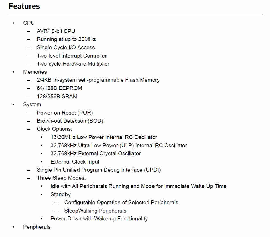
From the data sheet, my understanding is that the ATTiny 412 chip has the following features:
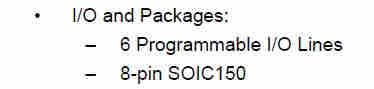
- 8 Pins in total
- 6 Programmable Lines (Used for I/O)
- 2 Pins Used for Power (VCC/ Ground)
- 1 Pin Used Specifically for Programming (UPDI)
- 2 Pins are assigned as Serial Communication (TX/RX)
- 3 Pins that can be used strictly for Input/Output (I/O) (These can ustilised for components such as; Button switches, low powered servos, LED’s )
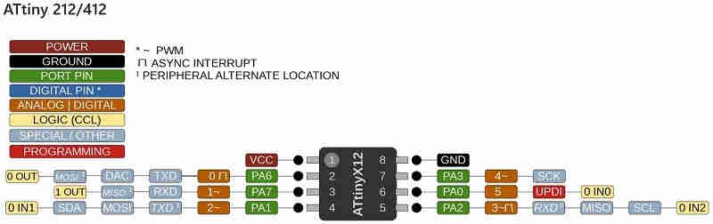
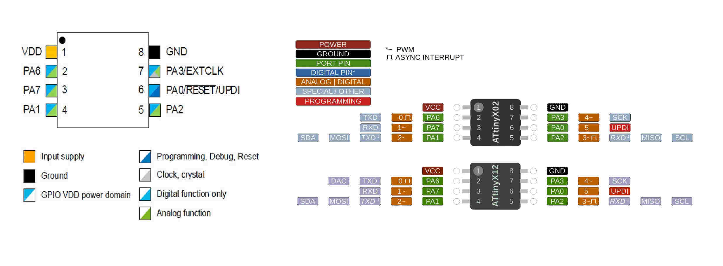
The image below shows the more detailed pinout for the aforementioned ATTiny 412 Chip
Programming
For the programming aspect, I utilsed a Arduino Uno (Sainsmart Branded, not really important). I downloaded and installed the Arduino IDE software. This interface allowed me to upload and program my arduino board as well as the board I would design for my final project (utilisng the ATTiny 412).
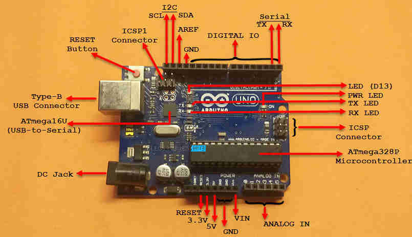
The above image shows a layout of the Arduino UNO board, and it’s labelled features.
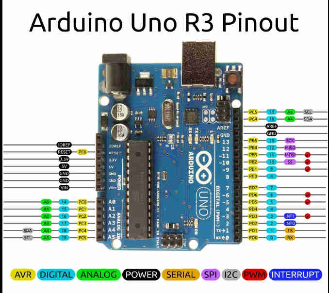
Here, image above, is sample of an Arduino Uno’s Pinout
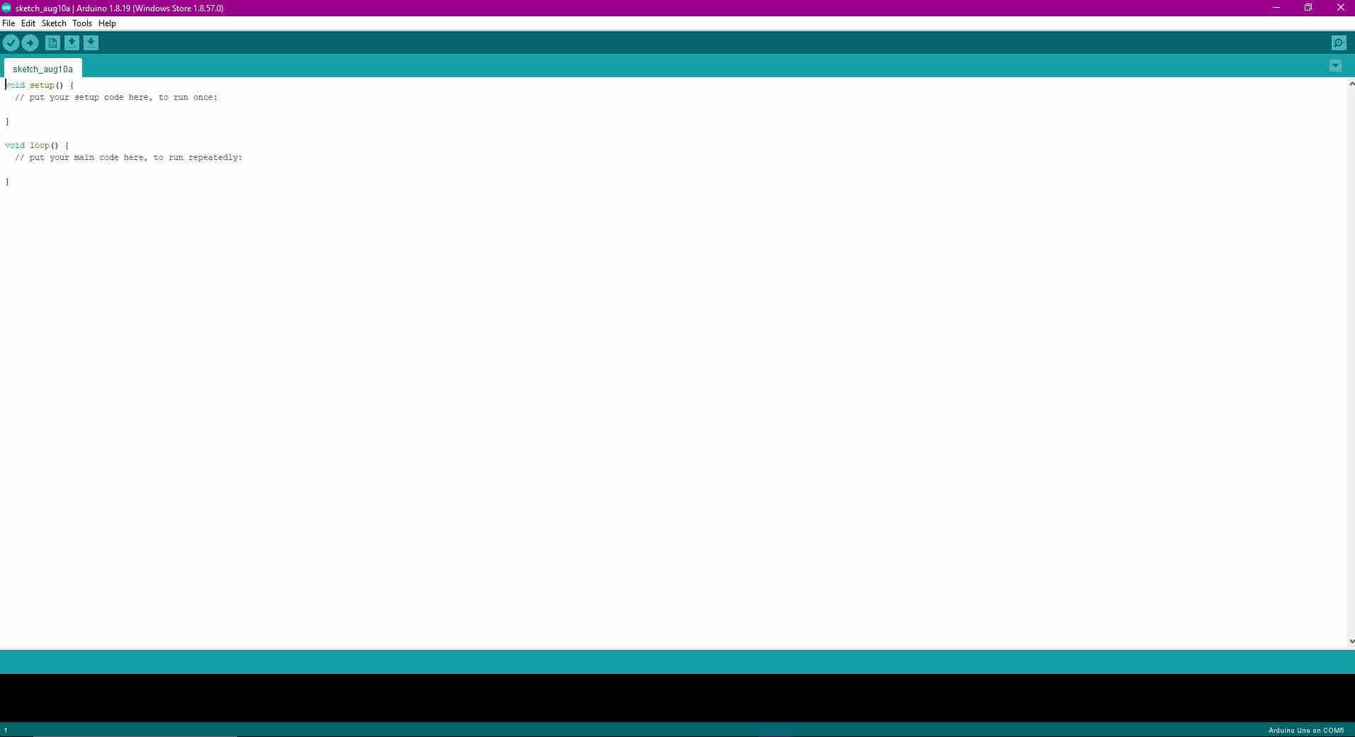
The above image shows the Arduino IDE Programming environment.
Process
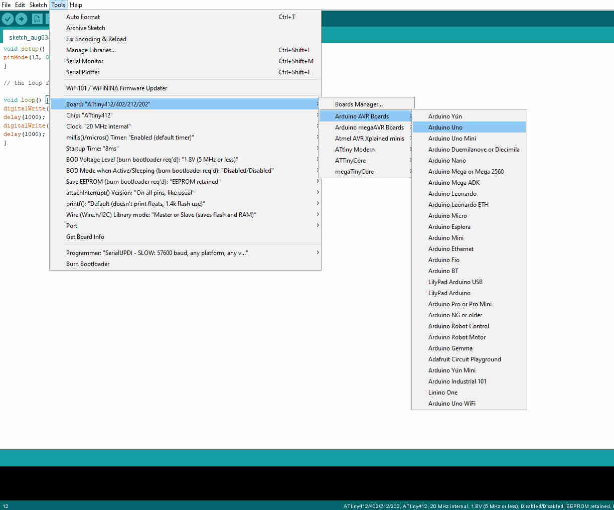
The first task when programming the Arduino Uno, within the Arduino IDE, was to select the correct board To do this, I used Tools>Board>Arduino Uno
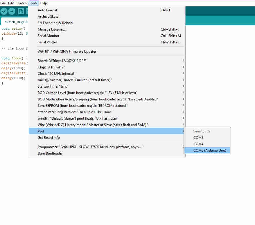
Secondly, the correct port should be selected. This is important as it opens the ideal chanel for the IDE to communicate with the board being programmed. Please note that port would only be recognised when the board is physically connected to the PC, via USB. This process entails selecting ; Tools>Port>COM (the corresponding port would be alocated when connected)
Thirdly, I wrote my code in the IDE, ensuring that it is clear an concise, meaning, if I were to misplace a colon for example, this error may render the program, nugatory or invalid. For this code, I utilised a simple blinking onboard LED. The LED in question is connected to PIN 13 on the Arduino UNO, as seen in my program code below:-
void setup() { // initialises the program
pinMode(13, OUTPUT);//assign pin 13 as an output
}

// the loop function runs over and over again forever

void loop() { //runs program over and over until stopped
digitalWrite(13, HIGH); // turn the LED on
delay(1000); // wait for one second
digitalWrite(13, LOW); // turn the LED off
delay(1000);
}
///
The above code instructs the LED to blink or come on and off for one second intervals. This code was taken from “Terrence Carew” ,(see useful links), as it was appropriate to fit my request.
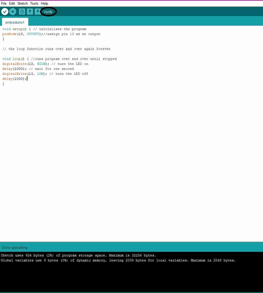
The code is then compiled and verified, as seen by the TICK icon located in the top left corner, under the file tab (As seen in the image below). This is done to ensure there are no errors present within the code prior to upload.
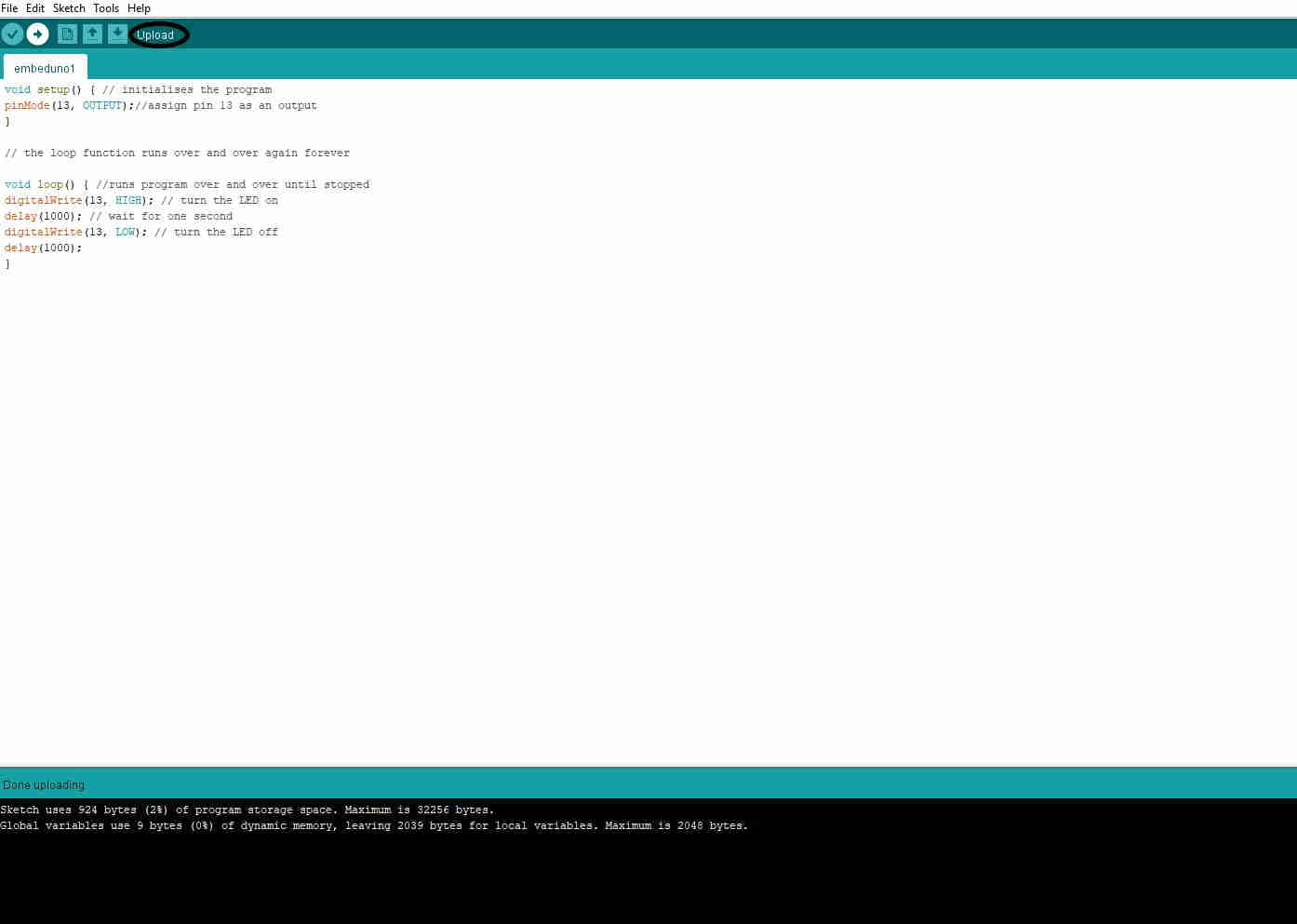
Once the verification process is rendered satisfactory, the code is then uploaded onto the arduino UNO board, as indicated by the ARROW POINTING RIGHT icon, located right of the verification icon, (as seen in the image below)
With the aformentioned processes completed, the program/ code is then stored onto the UNO board, and tested/ executed, as seen in the video below.
Useful Links
Group Assignment
For the Group Assignment, please refer to our Group Assignment Page - FAB Academy Group Page