3. Computer controlled cutting
This week I worked on defining my final project idea and started getting used to the documentation process. This is my attempt at using the Vinyl Cutter and Parametric design.
Group Assignment
Characterize Your Lasercutter’s Focus, Power, Speed, Rate, Kerf, Joint Clearance And Types.
Vinyl Cutting
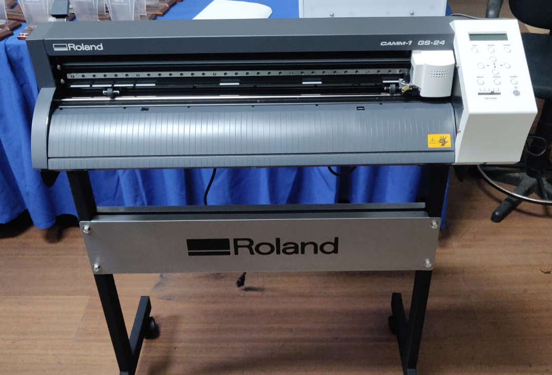
For the vinyl cutting aspect, I decided to opt out of designing my own intricate creation, and aquired a few images off the internet. I settled on 3 varied images. Firstly, I installed the Roland GS-24 software, Cut Studio, as well as the neccesary windows drivers.
- Next, I set my Force and Speed settings, to ensure a precise effcient cut from the machine, as seen in the image and video below


- Next, I familarised myself with the tools within Cut Studio Software. I changed a couple of the preferences, for example, changing the overall measurements from millimetres to inches, as inches would align with my expected result.

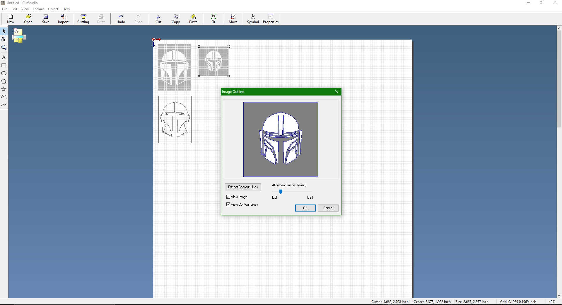
- Using cut studio, it was fairly straight forward in allowing me to import my image file, from which I was able to extract an outline, (it is important to have all cutting work done within the cutting grid space). After an image outline was extracted, just a few minor dimensioning details was needed.
- With the cutting done soley by the machine, it was just a simple method of taking the design and seperating the unwanted material from the wanted pieces (design). The method of achieving this is called weeding. Weeding has many methods, most of which involves the use of some “Dentist type” tools. However, due to my limited access to tools, I occasionally use a precise fine tip tweezers.
Below is the final result of my Vinyl work.

“The weeding process can sometimes be a time consuming one. It takes alot of patience, a focused mind and a pair of steady hands to get the job done! Painters tape, better known as masking tape makes an excellent transfer tape for vinyl cuts!”
Useful links
Parametric Design
Why parametric design? One of the benefits of parametric design is to increase speed, productivity whilst not comprimising on accuracy and detail. The essential goal of parametric design, is to add the dimensions and any other specific information needed for functionality and manufacturability.
Our assignment for this week was to create a design with interlocking pieces that utilise parametrics within the design process. Careful consideration was made to account for the kerf ( of 0.008 “) when cutting. The kerf in this case is the width of material thats removed when cutting, whether it be via CNC machining or laser cutting. An appropriate kerf can help ensure a tight fit for the notch pieces.
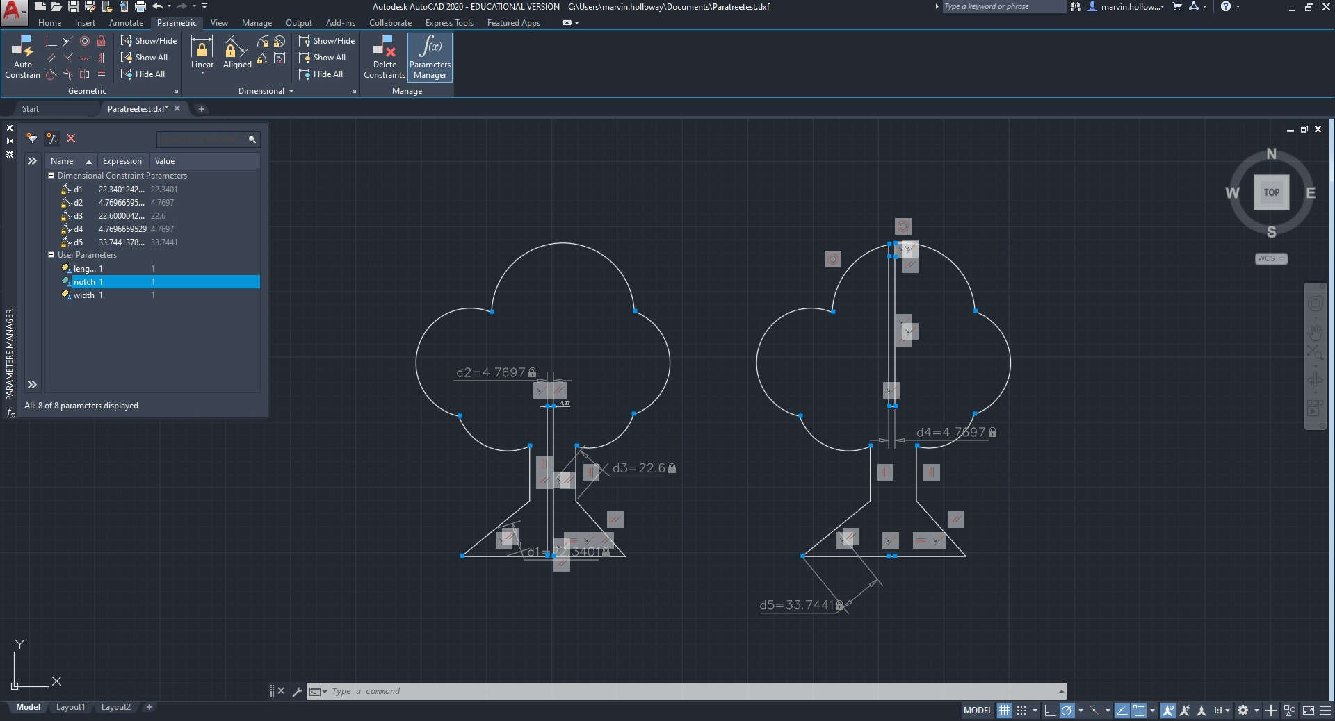
- Firstly, I used Autocad to create my drawing, a simple tree.
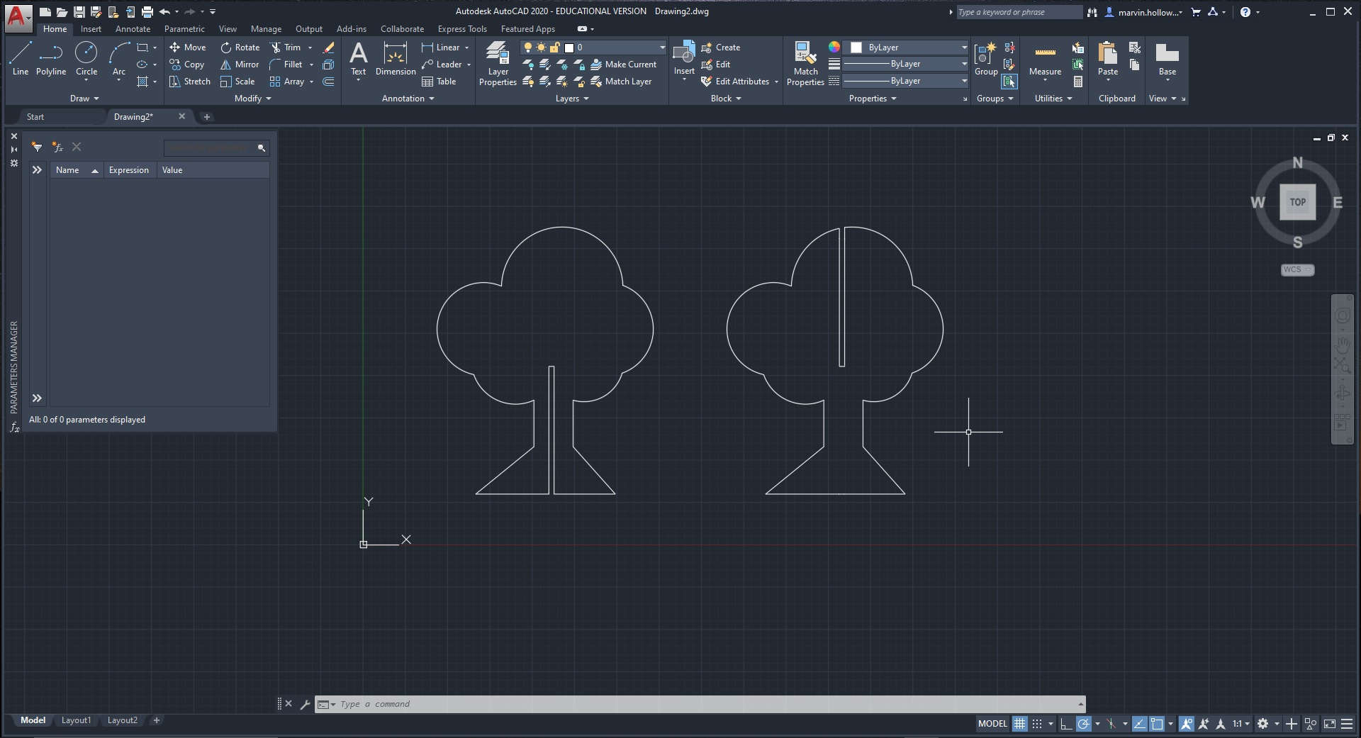
- Then I created and applied my parametrics via the parametric manager within autocad

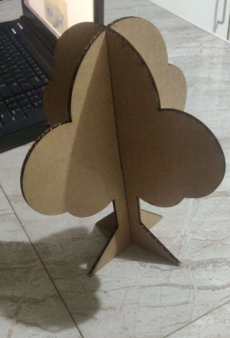
- By placing a notch from the midpoint of the tree to it’s base, then replicate that very same notch to a corresponding copy, then rotate it, I was able to get the 2 pieces needed to make a 2D to 3D represenattion of my tree. The notch was dimensioned to equate to the thickness of the cardboard material being used (Thickness Of cardboard _ [kerf*2]), again to ensure a tight fit when assembled.
DWG File Found Here Tree
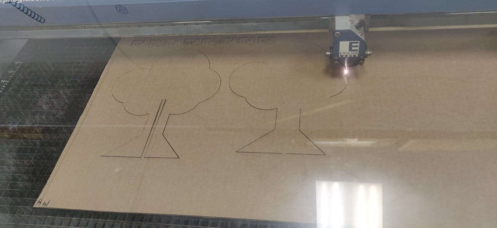
Assembly and Cutting
The machine available to me was the Epilog Laser Fusion. My file was sent in a .DXF format to the corel draw app, as it’s the native app we use to layout and edit images prior to cutting. However, there was an issue I encountered, I got a recurring unsupported code error when exporting my tree to corel draw. Luckily, I was able to remedy this by changing the compatability of my .dxf file within autocad.

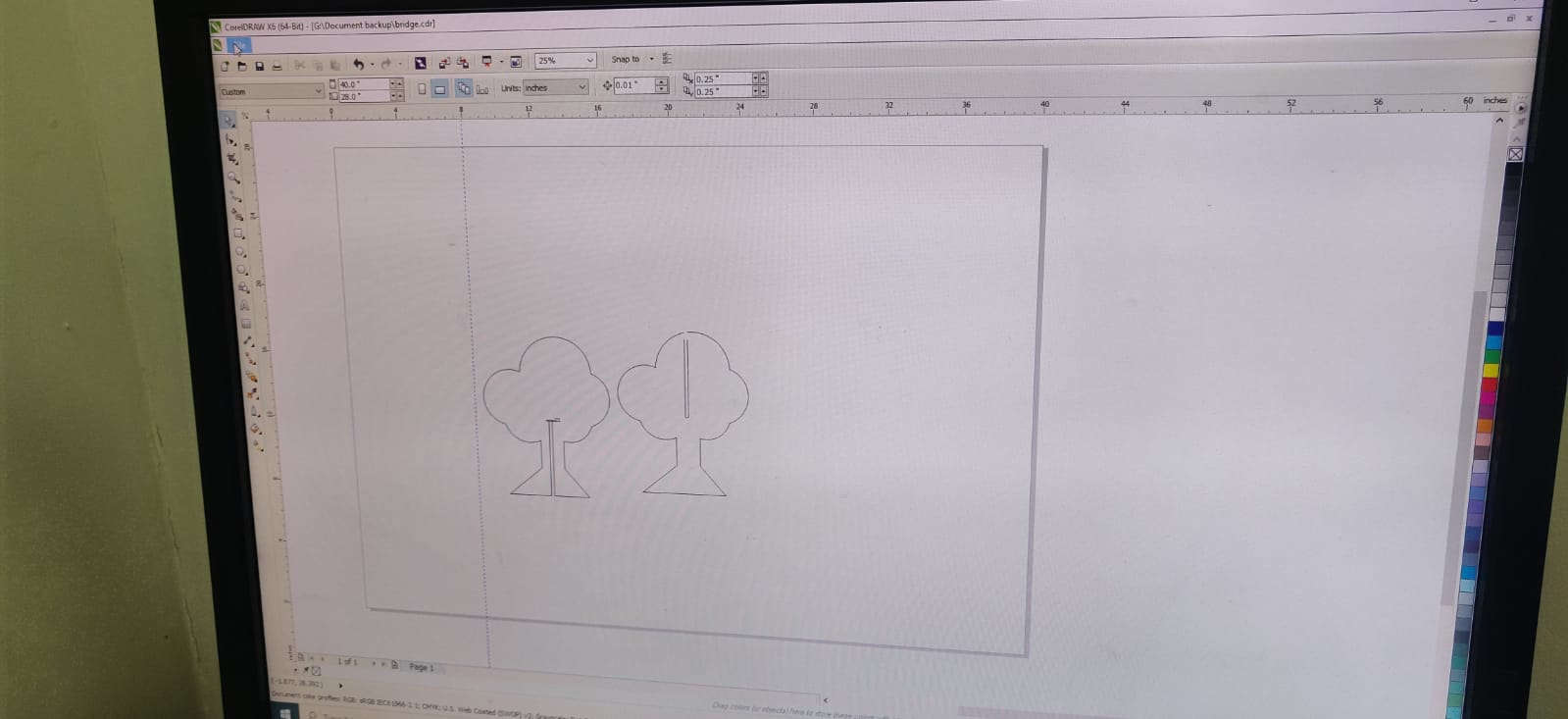
DXF File Found Here Tree/Cut
Helpful/Useful Info
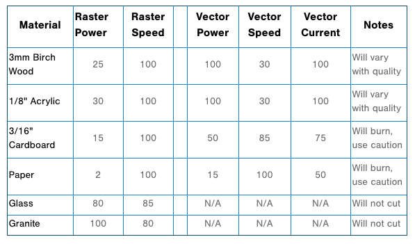
Below is a materials test for operating a Laser Cutter