15. Interface and application programming
This week I worked on prepare Python and LabVIEW to Interface and the schematic to simulation to act the commands.
Group Assignment:
- Compare as many tool options as possible.
Individual Assignment:
- Write an application that interfaces a user with an input &/or output device that you made
GROUP ASSIGNMENT
B) Interface with PYTHON: Work with Python’s Kivy tool
What is Kivy? Kivy is a free and open source Python framework for developing mobile apps and other multi-touch application software with a natural user interface. It is distributed under the terms of the MIT license and can be run on Android, iOS, Linux, macOS, and Windows.
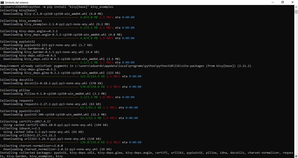
Installing Kivy with pip in Python for Windows:
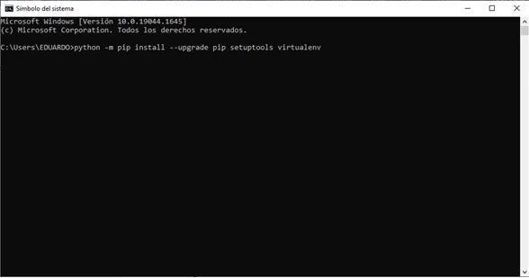
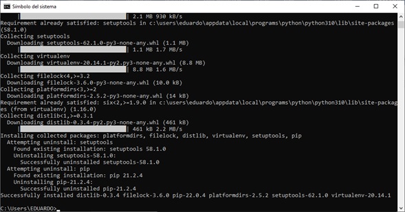
- For this, it is suggested to install the necessary tools, using the following commands in the Python IDLE:
a) python -m pip install –upgrade pip setuptools virtualenv
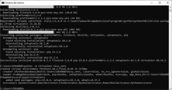
b) python -m virtualenv kivy_venv
c) kivy_venv\Scripts\activate (Upon completion, the console must be closed for it to take effect)
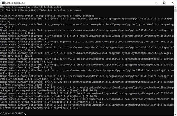
d) python -m pip install “kivy[base]” kivy_examples
python -m pip install --upgrade pip setuptools virtualenv
python -m pip install --upgrade pip setuptools virtualenv
python -m pip install --upgrade pip setuptools virtualenv
python -m pip install --upgrade pip setuptools virtualenv
LabVIEW:
- I have worked with LabVIEW before. LabVIEW is a graphical programming software (G-code) that consists of two parts: the front panel which is the Graphical User Interface (GUI) and the block diagram window which is where the programming is done in G-code. Below on the page is a link where to get more information..
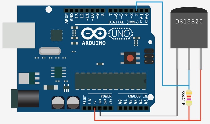
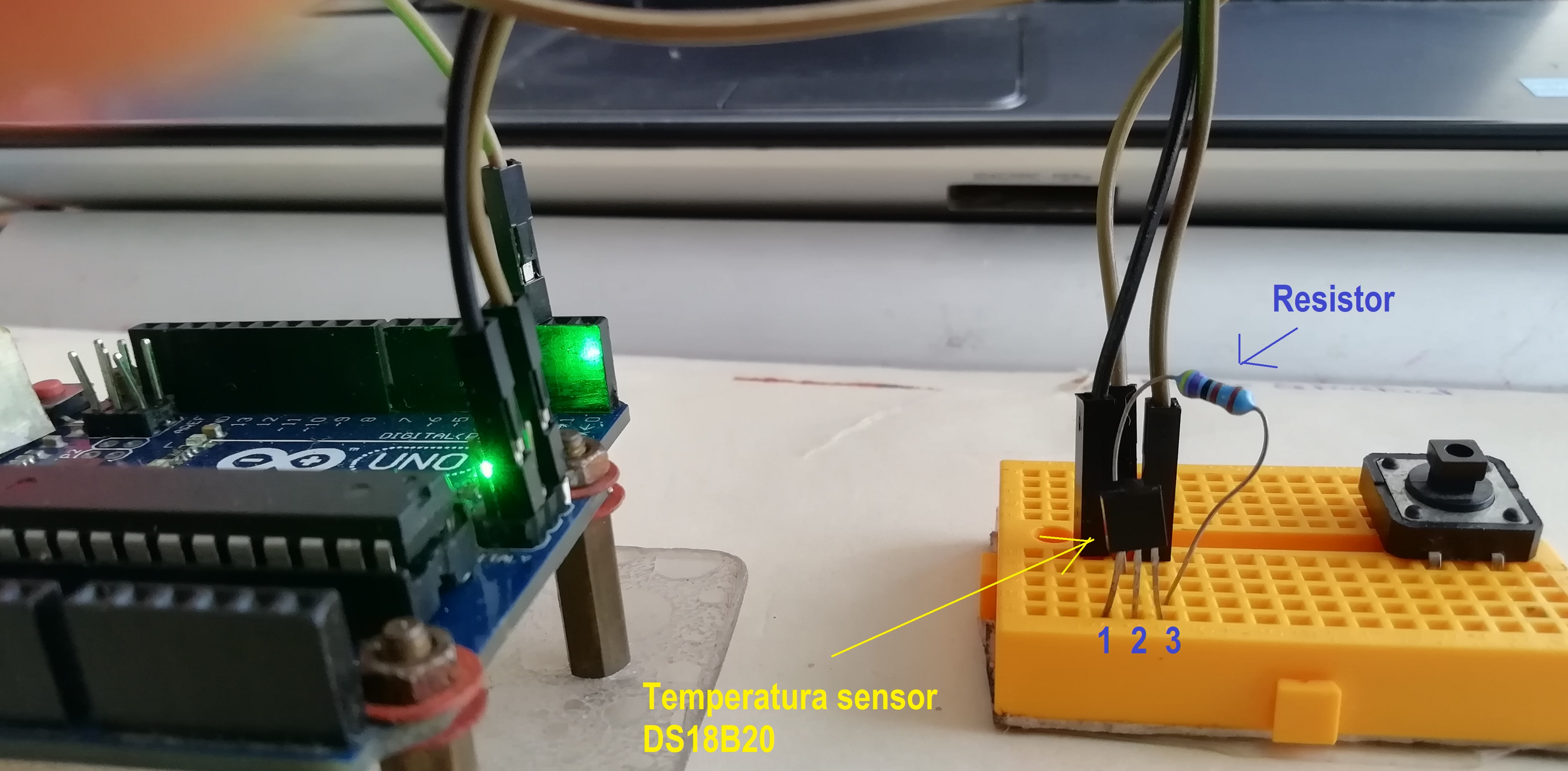
- I will try to make a temperature meter with the DS18B20 sensor (below is a link for more details). I will use arduino as hardware. This is the diagram I am going to implement:
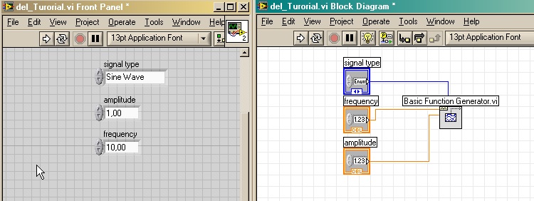
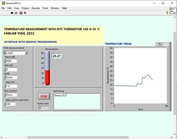
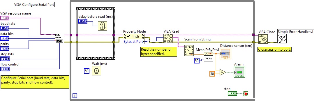
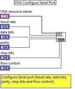
- First I start building the graphical interface (GUI) on the LabVIEW front panel.
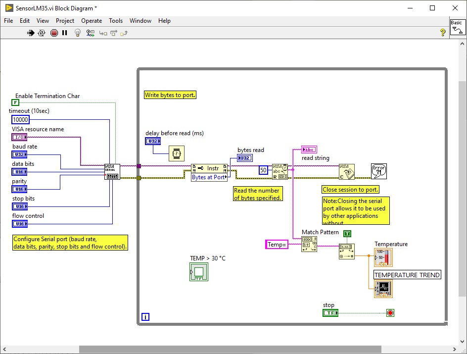
- The graphic blocks and their wiring are as follows:
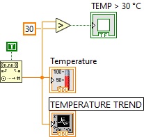
- I add the “greater than” comparator, if the temperature is greater than 30 °C turn on the LED.
-
The LabVIEW program reads the serial port (RS-232) and captures the frame “Temp=” from there it displays the number after the frame which is the temperature value. The capture time between frames is 50 ms. The program that I will make in Arduino must send the data in a time equal to or less than 50 ms so that no data is lost.
-
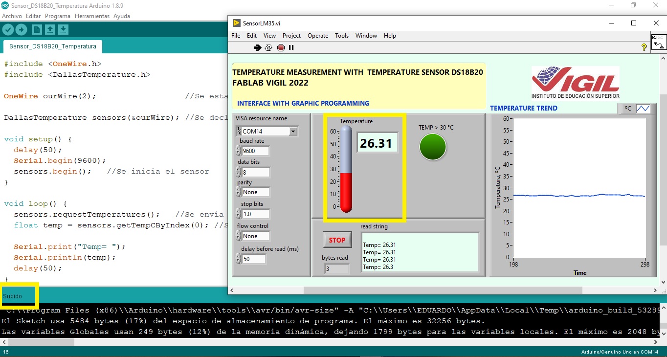
The Arduino program is as follows:
/* Temperature sensor - LabVIEW
   Sensor: DS18B20
   Pinout:
   Sensor    --> Arduino
   Pin1(GND) --> GND
   Pin2(Out) --> A2
   Pin3(Vcc) --> 5V
****************************************************
 Alberto E. Cohaila B. - FabAcademy 2022
****************************************************
 Temperature sensor - LabVIEW - ATMega328
****************************************************
*/

#include <OneWire.h>
#include <DallasTemperature.h>

OneWire ourWire(2);                  //Se establece el pin 2  como bus OneWire

DallasTemperature sensors(&ourWire); //Se declara una variable u objeto para nuestro sensor

void setup() {
  delay(50);
  Serial.begin(9600);
  sensors.begin();   //Se inicia el sensor
}

void loop() {
  sensors.requestTemperatures();   //Se envía el comando para leer la temperatura
  float temp = sensors.getTempCByIndex(0); //Se obtiene la temperatura en ºC

  Serial.print("Temp= ");
  Serial.println(temp);
  delay(50);
}
- I compile and transfer to the Arduino. Then I run the temperature program in LabVIEW. Here is the result:
- A short video can be seen here:
HTTP: WEB SERVER WITH WEMOS ESP8266
-
I am going to use the WEMOS ESP8266 and try to light an LED via web page.
-
In the Arduino IDE Board Manager: Tools >> Board: “Arduino” >> Board Manager....
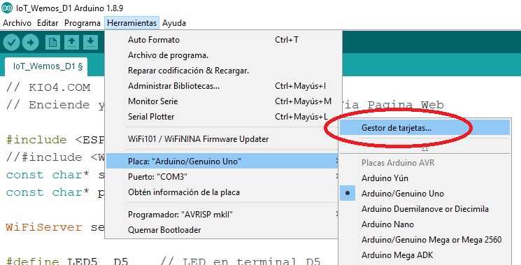
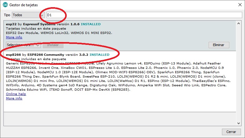
- In the search field enter D1. Select esp8266, click on Install
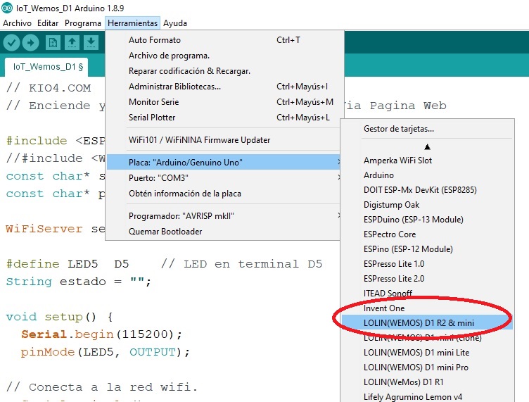
- Then select the WEMOS board: Tools>>Board>>>LOLIN (WEMOS)D1 R2 and mini
- Open a new file and copy the following code:
/* ESP8266MOD WEB SERVER
   LED --> Pin D5
****************************************************
 Alberto E. Cohaila B. - FabAcademy 2022
****************************************************
 Turns LED on and off. Buttons. Images Via Web Page
****************************************************
*/

#include <ESP8266WiFi.h>
//#include <WiFi.h> // Para el ESP32
const char* ssid = "ARYAN";         //Nombre de Red WIFI
const char* password = "aryan2020"; //Clave de Red WIFI

WiFiServer server(80);

#define LED5  D5    // LED en terminal D5
String estado = "";

void setup() {
  Serial.begin(115200);
  pinMode(LED5, OUTPUT);

// Conecta a la red wifi.
  Serial.println();
  Serial.print("Conectando con ");
  Serial.println(ssid);

  WiFi.begin(ssid, password);

  while (WiFi.status() != WL_CONNECTED) {
    delay(500);
    Serial.print(".");
  }
  Serial.println("Conectado con WiFi.");

  // Inicio del Servidor web.
  server.begin();
  Serial.println("Servidor web iniciado.");

  // Esta es la IP
  Serial.print("Esta es la IP para conectar: ");
  Serial.print("http://");
  Serial.println(WiFi.localIP());
}

void loop() {
  // Consulta si se ha conectado algún cliente.
  WiFiClient client = server.available();
  if (!client) {
    return;
  }

  Serial.print("Nuevo cliente: ");
  Serial.println(client.remoteIP());

  // Espera hasta que el cliente envíe datos.
  while(!client.available()){ delay(1); }

  /////////////////////////////////////////////////////
  // Lee la información enviada por el cliente.
  String req = client.readStringUntil('\r');
  Serial.println(req);

  // Realiza la petición del cliente.
       if (req.indexOf("on5") != -1) {digitalWrite(LED5, HIGH); estado = "Encendido";}
       if (req.indexOf("off5") != -1){digitalWrite(LED5, LOW); estado = "Apagado";}
       if (req.indexOf("consulta") != -1){
                       if (digitalRead(LED5)){estado = "Ahora Encendido";}
                       else {estado = "Ahora Apagado";}
                       }

  //////////////////////////////////////////////
  // Página WEB. ////////////////////////////
  client.println("HTTP/1.1 200 OK");
  client.println("Content-Type: text/html");
  client.println(""); //  Importante.
  client.println("<!DOCTYPE HTML>");
  client.println("<html>");
  client.println("<head><meta charset=utf-8></head>");
  client.println("<body><center><font face='Arial'>");
  client.println("<h1>Servidor web con ESP8266.</h1>");
  client.println("<h2><font color='#009900'>ELECTRONICA INDUSTRIAL - Fundamentos de Industria 4.0</font></h2>");
  client.println("<a href='on5'><button>Enciende LED5</button></a>");
  client.println("<a href='off5'><button>Apaga LED5</button></a>");
  client.println("<a href='consulta'><button> Consulta estado </button></a><br>");
  client.println("<br><br>");
  if(estado == "Encendido") {
    client.print("<a href='off5'><button> Apaga el LED5</button></a><br><br>");
    client.println("<img src='http://www.clker.com/cliparts/M/h/R/9/8/H/red-led-on-md.png'><br>");
  } else {
  client.print("<a href='on5'><button> Enciende el LED5</button></a><br><br>");
  client.println("<img src='http://www.clker.com/cliparts/X/A/P/f/5/n/red-led-off-md.png'><br>");
  }
  client.println("</font></center></body></html>");

  Serial.print("Cliente desconectado: ");
  Serial.println(client.remoteIP());
  client.flush();
  client.stop();
}
- Compile and Transfer the code to the WEMOS ESP8266 D1.
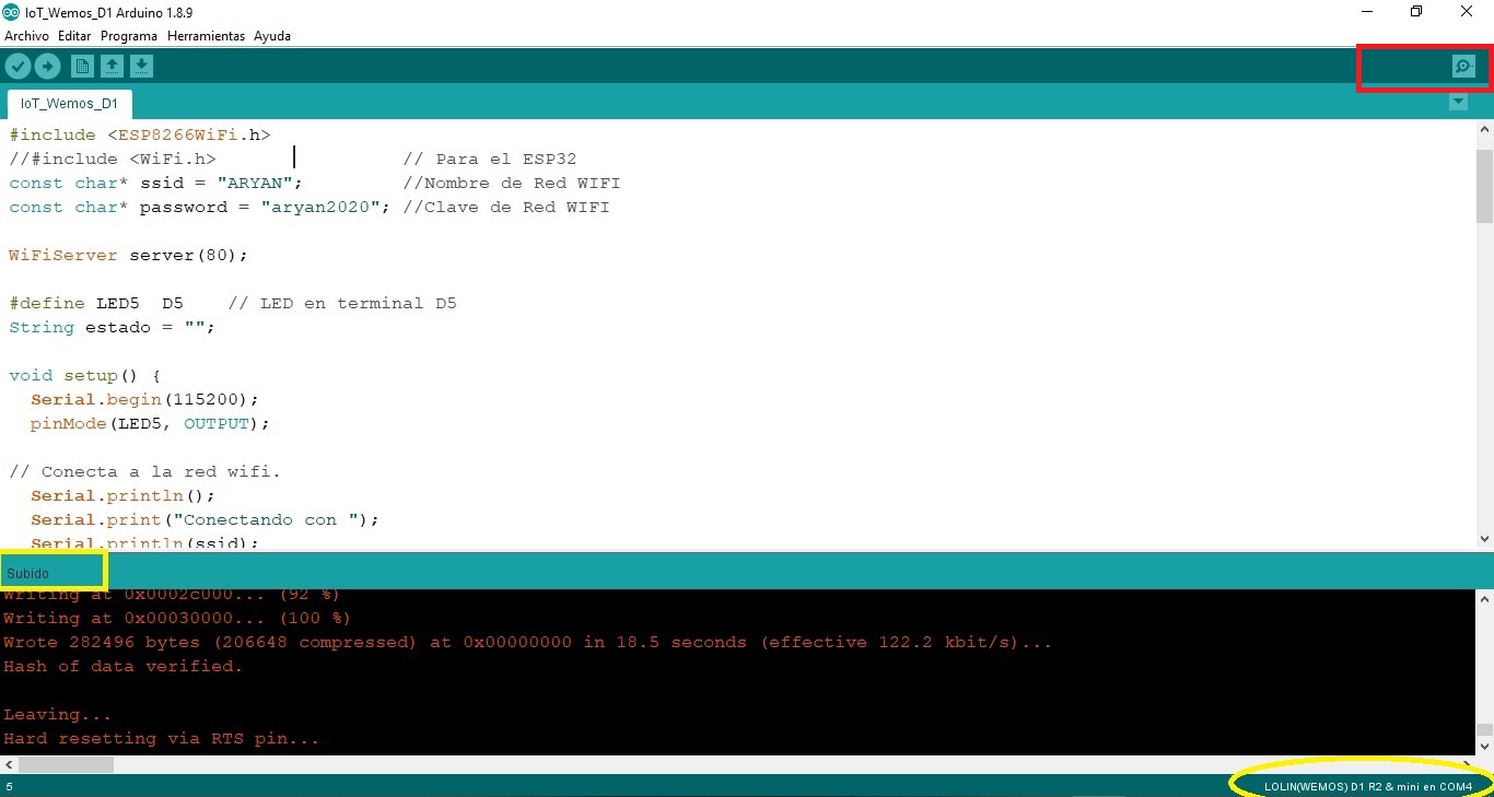
- Click on Serial monitor. Set the speed to 115200 and press the RESET button of the WEMOSD1:
Note: You must have an Internet connection for the WEMOS to connect to the router and assign an IP address automatically.
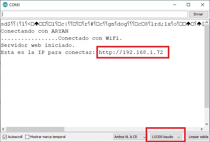
- In the Google search engine type the IP address of the WEMOS: in our case 192.168.1.72.
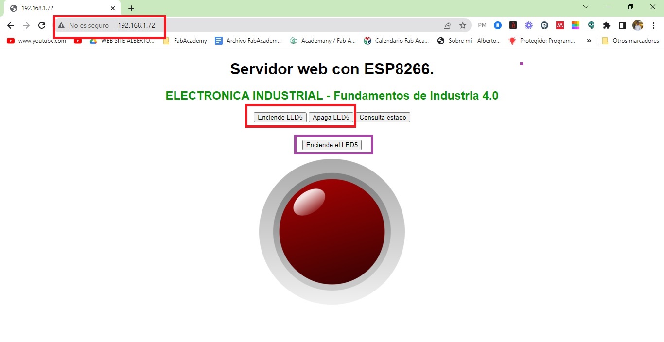
- Connect an LED with its respective resistor to Pin D5 of the WEMOS ESP8266 board and turn on/off using the buttons on the Web Server.
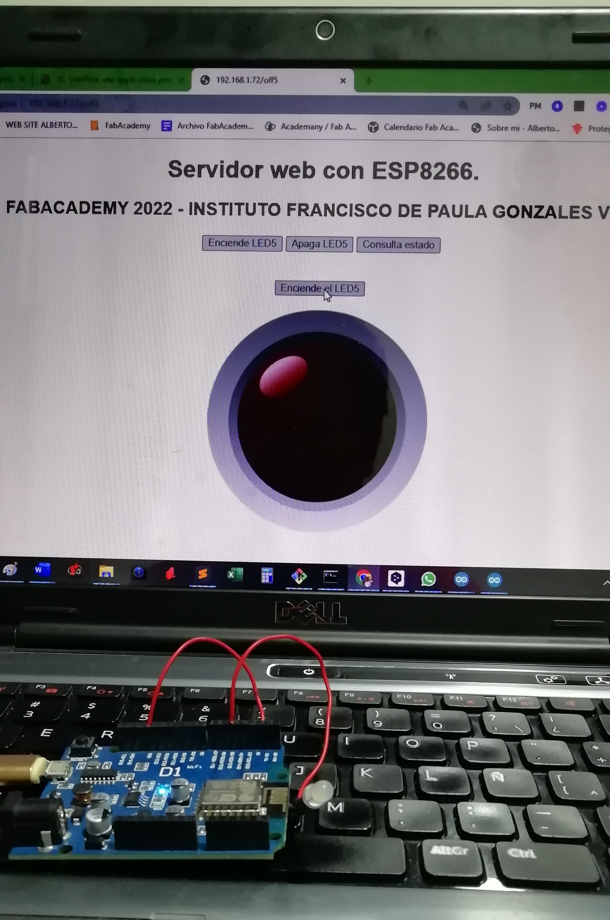
- All went well, the LED turns on and off from the web page. Here is the video of the heroes of the group:
INDIVIDUAL ASSIGNMENTS
- I have these sensors on hand, I will try to use two of these that will be useful later for the final project.
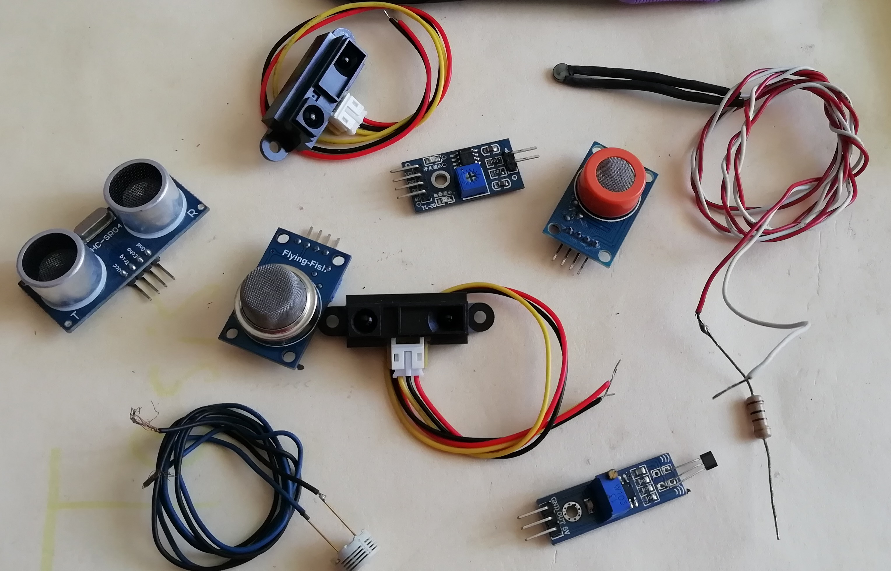
- I decide to use the LOGO-sensor V1.3 fire sensor and the SHARP 2Y0A21 distance sensor. The following image shows the flame or fire sensor:
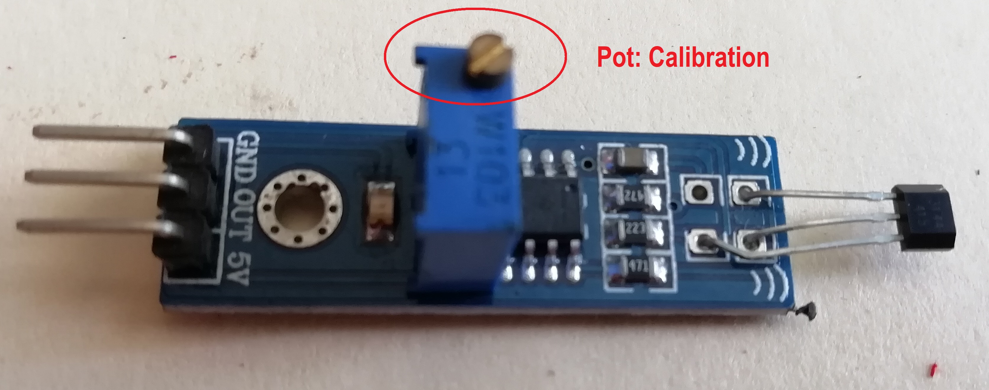
-
This sensor has a linear potentiometer for flame or fire intensity calibration, usually factory set.
-
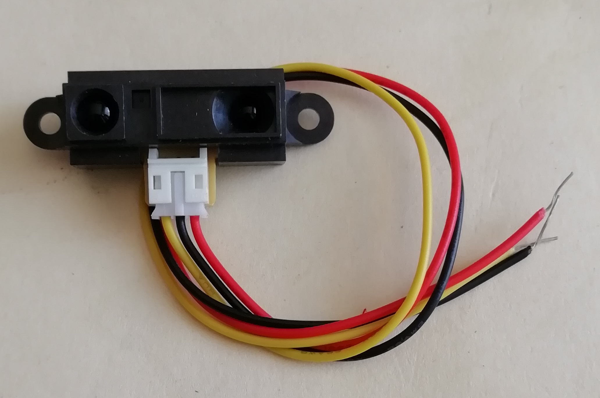
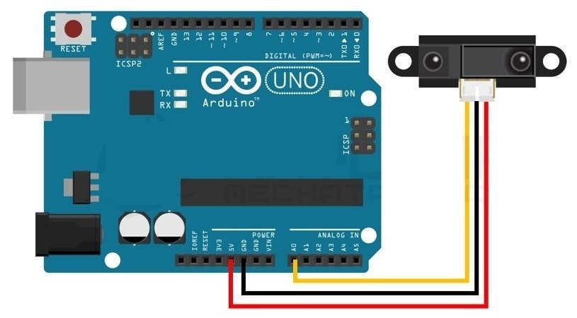
This is the SHARP 2Y0A21 distance sensor. Both sensors use 3 wires. One for the physical variable signal and two for power.
Hall efect sensor
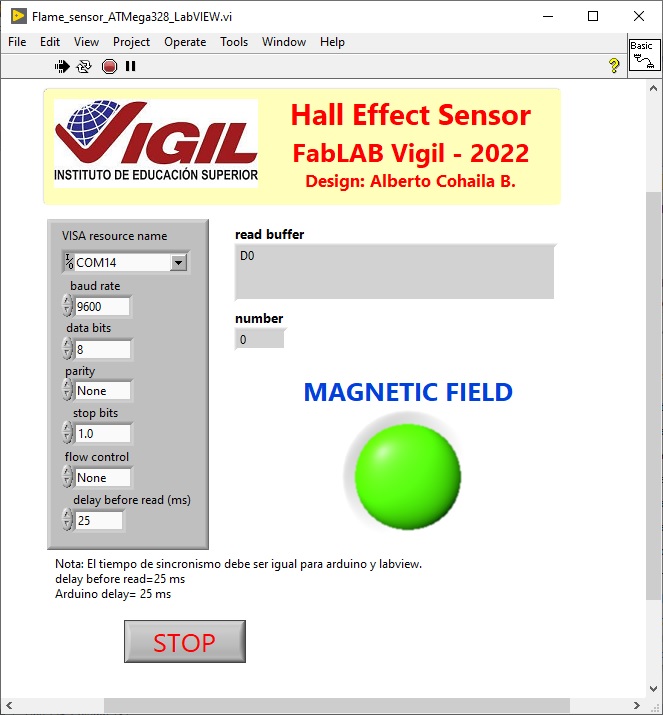
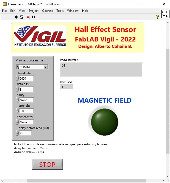
- First I will try to make a program with the ATMega328 and then I will make the communication with LabVIEW. In LabVIEW I will program a graphical interface where I will see the status of the hall effect sensor, i.e., it will activate an LED when there is presence of magnetic field, otherwise it will be off.
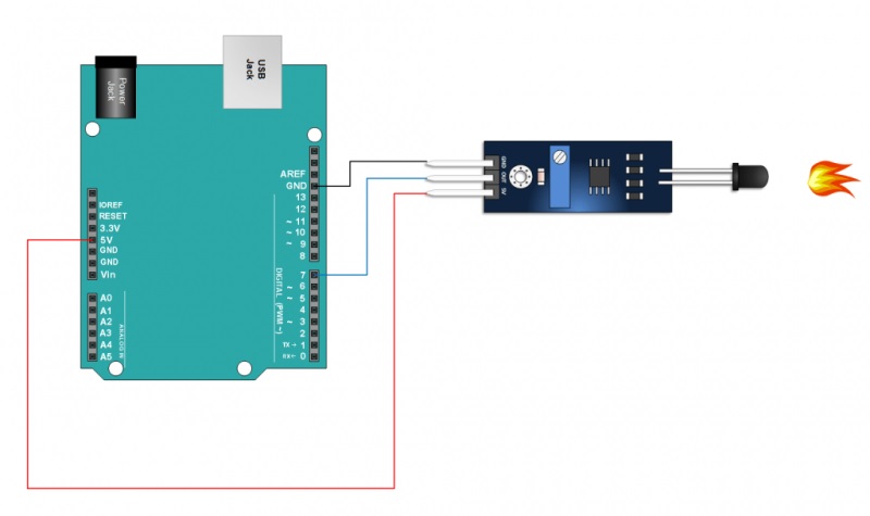
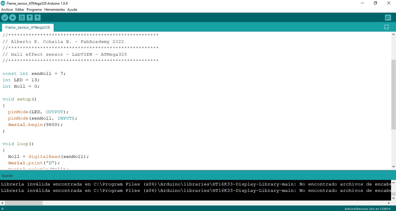
- The code for the ATmega 328 (Arduino) is as follows:
/* Hall effect sensor - LabVIEW
   Sensor: LOGO-Sensor ver.13
   LED 13 lights up when a magnetic field is detected. The alert is seen in LabVIEW.
   Pinout:
   Sensor --> Arduino
   Out    --> pin7
*/
//****************************************************
// Alberto E. Cohaila B. - FabAcademy 2022
//****************************************************
// Hall effect sensor - LabVIEW - ATMega328
//****************************************************

const int senHoll = 7;
int LED = 13;
int Holl = 0;

void setup()
{
  pinMode(LED, OUTPUT);
  pinMode(senHoll, INPUT);
  Serial.begin(9600);
}

void loop()
{
  Holl = digitalRead(senHoll);
  Serial.print("D");
  Serial.println(Holl);
  if (Holl == 1)
  {
    digitalWrite(LED, LOW);
  }
  else
  {
    digitalWrite(LED, HIGH);
  }
  delay (50);
}
- Then, I transfer the program to ATMega 328
- Now I do the graphical programming in LabVIEW to read data through the serial port (RS-232). The ATMega 328 is programmed to send data through the RS-232 port at a rate of 9600 baudios.
LabVIEW Programming
- LabVIEW consists of two windows: The front panel and the block diagram which is where you program in graphical code. The front panel is:
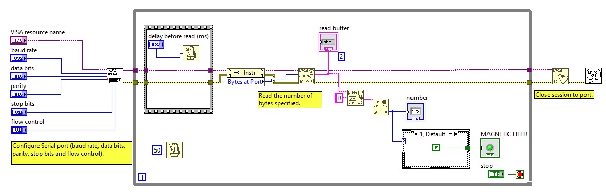
- And the block diagram is:
- Here is a video:
Distance sensor
- Now I will try the SHARP 2Y0A21 distance sensor. This sensor has an analog output. I start first with the connection to the Arduino. Then I make the program.
- The range of distance measurement is from 10 to 80 cm, according to the manufacturer’s data sheet:
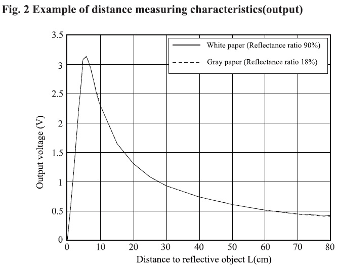
- From the datasheet curve we only take the exponential form but taking into account that the equation will work within the working range of the sensor between 10 and 50 cm.
-
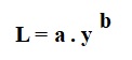
The voltage and the discrete levels of the ADC that we read from the arduino are proportional, we will find the equation as a function of the ADC value, this in order to save us a calculation by the arduino to obtain the voltage. So for us “y” is the value of the ADC.
-
I made two measurements of readings at 10 cm and 50 cm. This part was the most complicated, because I had to make 3 runs to verify the measured values very close to the real one. First I load the calibration program to the arduino, I make two measurements. Here is a picture of the process.
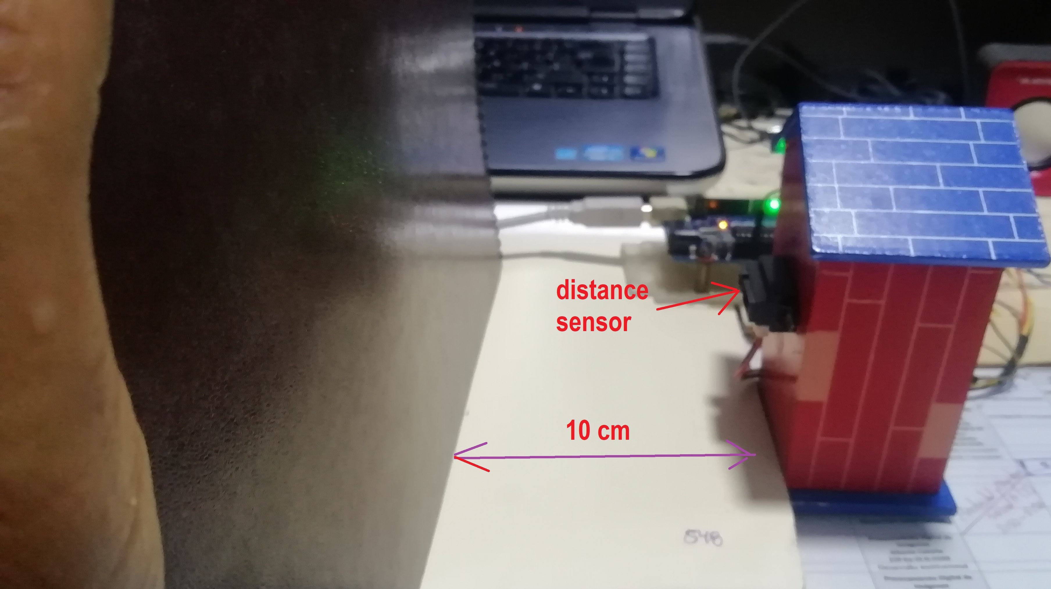
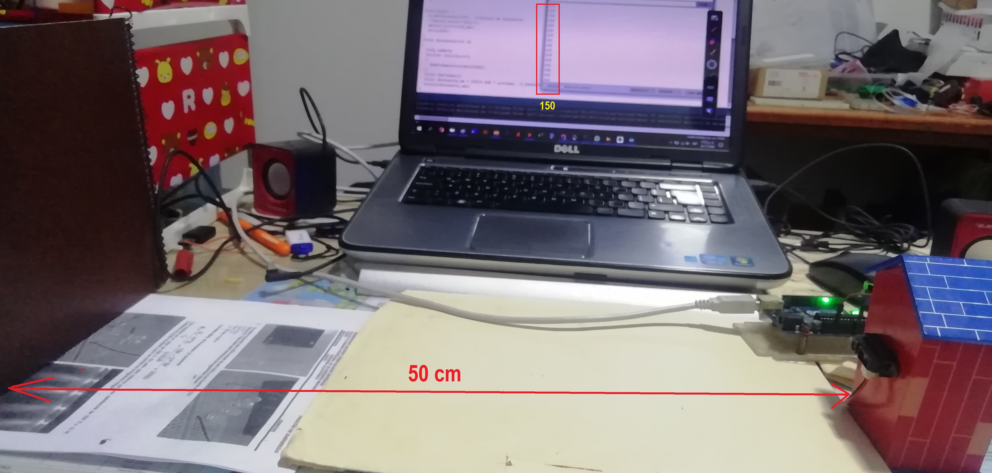
- The results of the point calibration process are as follows:
Y1 = 540 for L1 = 10 cm
Y2 = 150 for L2 = 50 cm
- Replacing these values in the equation, we can form a system of 2 equations and find the variables “a” and “b”:
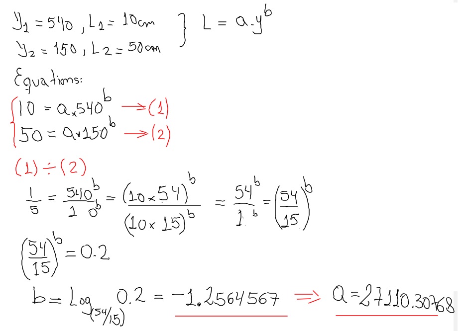
- The variables found “a” and “b” are:
a = 27110.30768
b = -1.2564567
- Then I obtain the equation of the distance sensor given by:
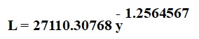
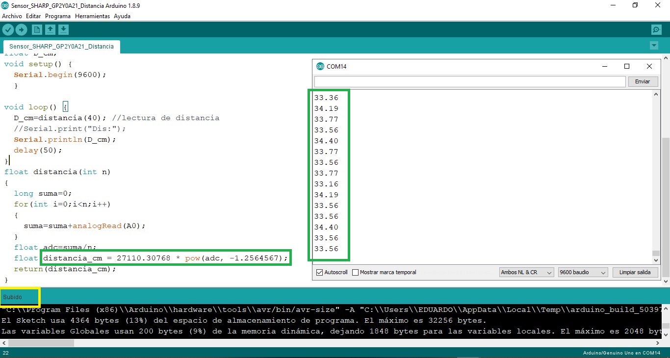
- With this equation I can make the program to obtain the distance measurement. I compile the program and transfer it to the Arduino.
/* Distance sensor - LabVIEW
   Sensor: SHARP 2Y0A21
   Pinout:
   Sensor --> Arduino
   Out    --> A0
****************************************************
 Alberto E. Cohaila B. - FabAcademy 2022
****************************************************
 Distance sensor - LabVIEW - ATMega328
****************************************************
*/
float D_cm;
void setup() {
  Serial.begin(9600);
  }

void loop() {
  D_cm=distancia(40); //lectura de distancia
  //Serial.print("Dis:");
  Serial.println(D_cm);
  delay(50);
}
float distancia(int n)
{
  long suma=0;
  for(int i=0;i<n;i++)
  {
    suma=suma+analogRead(A0);
  }
  float adc=suma/n;
  float distancia_cm = 27110.30768 * pow(adc, -1.2564567);
  return(distancia_cm);
}
- Now I make the program to read data through the serial port in LabVIEW
- Programming the LabVIEW front panel:
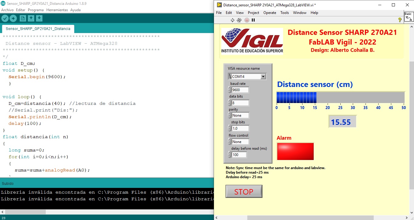
- The block diagram, where it is programmed graphically, is shown in the figure. An averager has been placed for 50 distance samples because this sensor presents a lot of noise. The manufacturer recommends placing a 10 uF capacitor to reduce the electrical noise.
- Here is another video:
Using ATTiny44 in serial communication:
- Use the Hello_ATTiny44_ISP.ino program from assignment 7. Modify the program to perform the serial data transmission to LabVIEW. The PCB does not have a serial port, so I had to create a virtual serial port which is usually called UART (Universal Asynchronous Transmitter/Receiver).
Switching on an LED via pushbutton with ATTiny44 and LabVIEW 2018
-
By means of a pushbutton (connected to PA2) the LED in LabVIEW must be switched on.
-
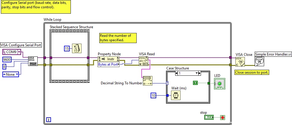
First I configure the serial port, this is similar to void setup()
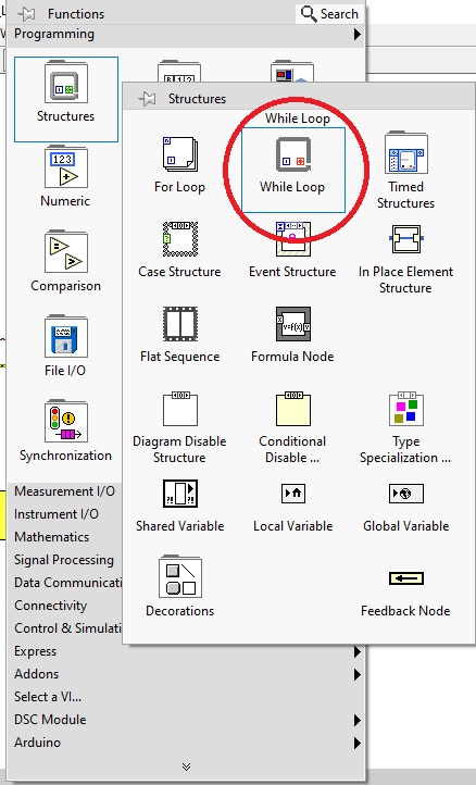
- I create an infinite while loop, it is similar to void loop() in arduino
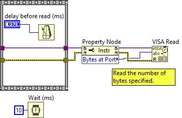
- Inside the while loop I perform a delay before opening the serial port, then the Property Node block allows to see the data that are stored in the memory buffer. With Visa Read I visualize the data string.
- The data frame is unique: “0” and “1”. I convert the String frame to decimal number of integer type. Then a case structure transforms the data to binary. Case “0” corresponds to the value False or “logical 0”.
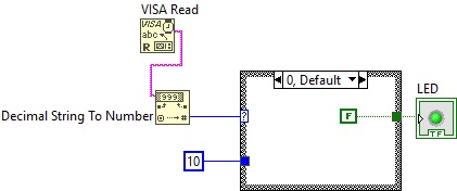
- Case “1” corresponds to the value True or “logic 1”. These two conditions turn the LED on and off respectively.
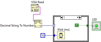
- The final graphic code is as follows:
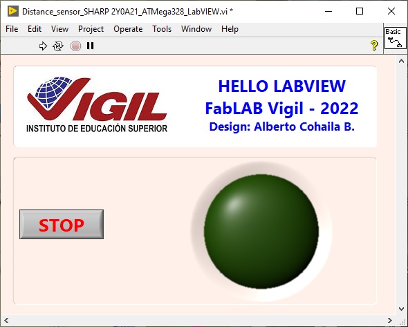
- The front panel is:
- Then I make the ATTiny44 microcontroller program, I do this in the Arduino IDE. I compile it and it is ready to transfer:
/*Hello LabVIEW - ATTiny44A
  Pin configuration:
  ATtiny44 PA3 (pin 10)--> Green LED connected
  ATtiny44 PA2 (pin 11)--> Pushbutton connected
  Switch on and off an LED via external push button
*/

#include <SoftwareSerial.h>
#define pin_tx 0
#define pin_rx 1
SoftwareSerial mySerial(pin_rx, pin_tx); // RX, TX

const int LED = 3;
const int BOTON = 2;
int val;

void setup() {
  pinMode(LED, OUTPUT);
  pinMode(BOTON, INPUT);
  mySerial.begin(9600);
}
void loop() {
  val = digitalRead(BOTON);
  if  (val == LOW) {
    digitalWrite(LED, HIGH);
    mySerial.println(HIGH);
  }
  else {
    digitalWrite(LED, LOW);
    mySerial.println(LOW);
  }
 delay (25);
}
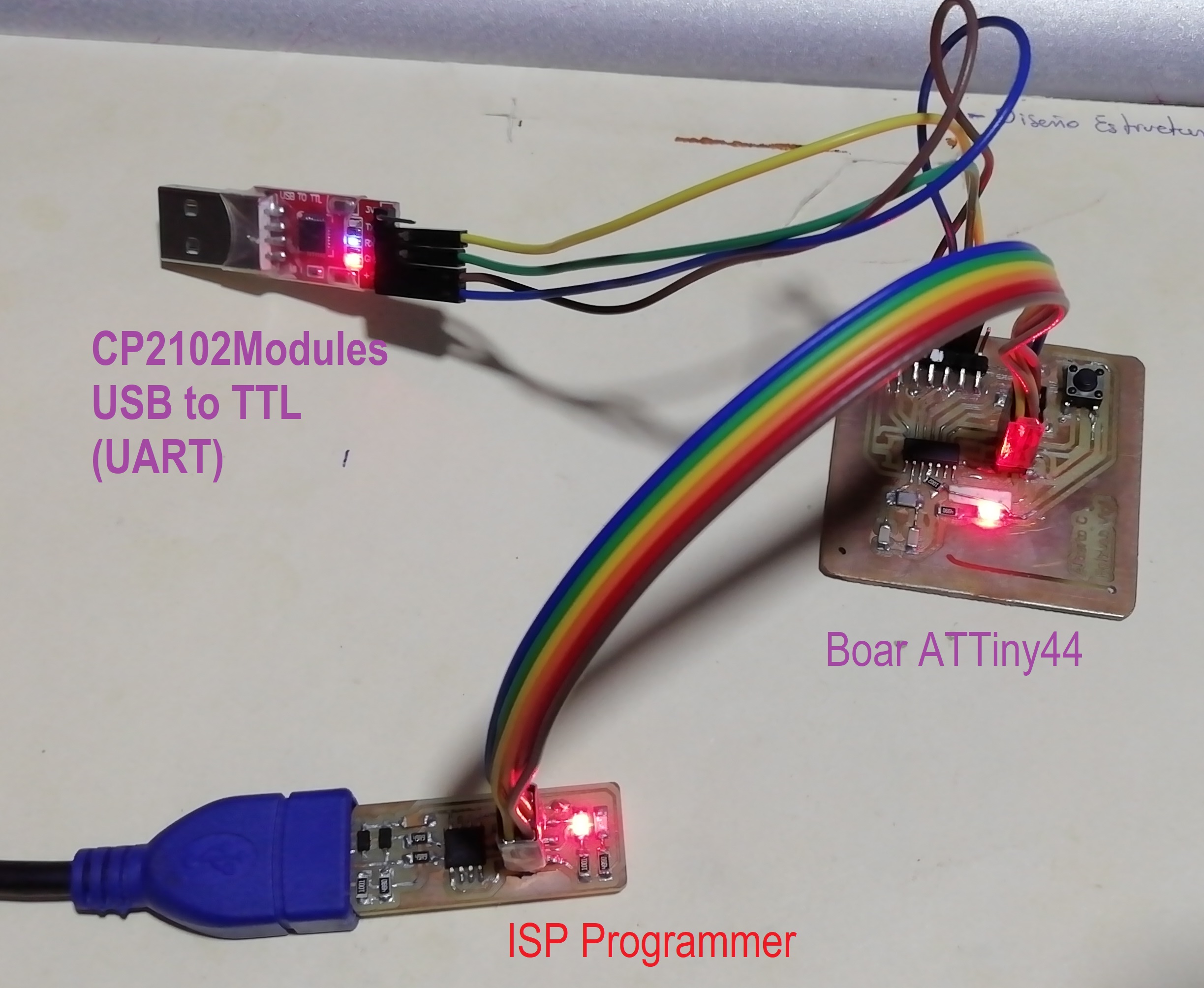
- The connection with the programmer and the data converter is:
- This is a video of the PCB hero:
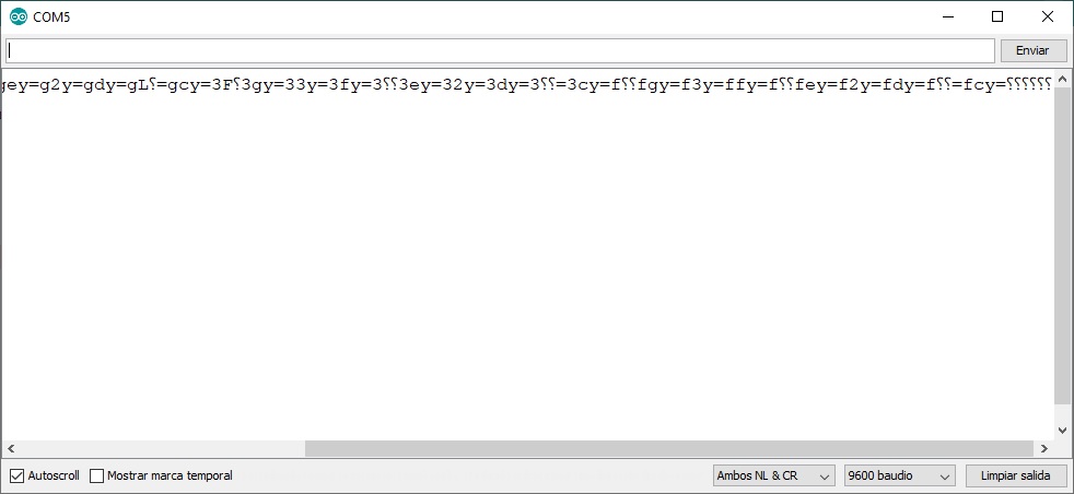
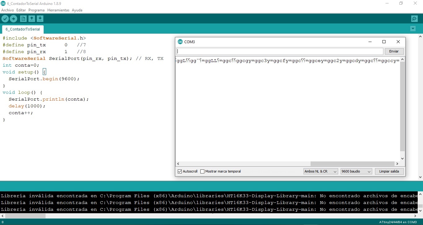
What problems did I have?
- When I was transmitting or receiving data through the serial port, I was seeing a string of strange characters, I assumed it was the data format, so I tried to solve it by sending data in decimal, hexadecimal and binary format without success. So I talked about this to my instructor and he told me that I should use a USB to UART converter. Well, it was logical because the ATTiny does not have its own serial communication port.
-
The Fablab where I perform the tasks, does not have this converter, so I decided to look for it in the local electronics stores. I tried with the converter and I could see the data sent/received by the ATTiny in a normal way.
-
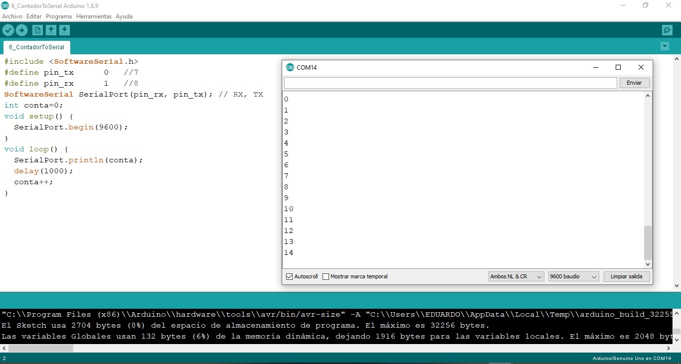
I tried an ascending counter provided by my instructor.
How to solve it?
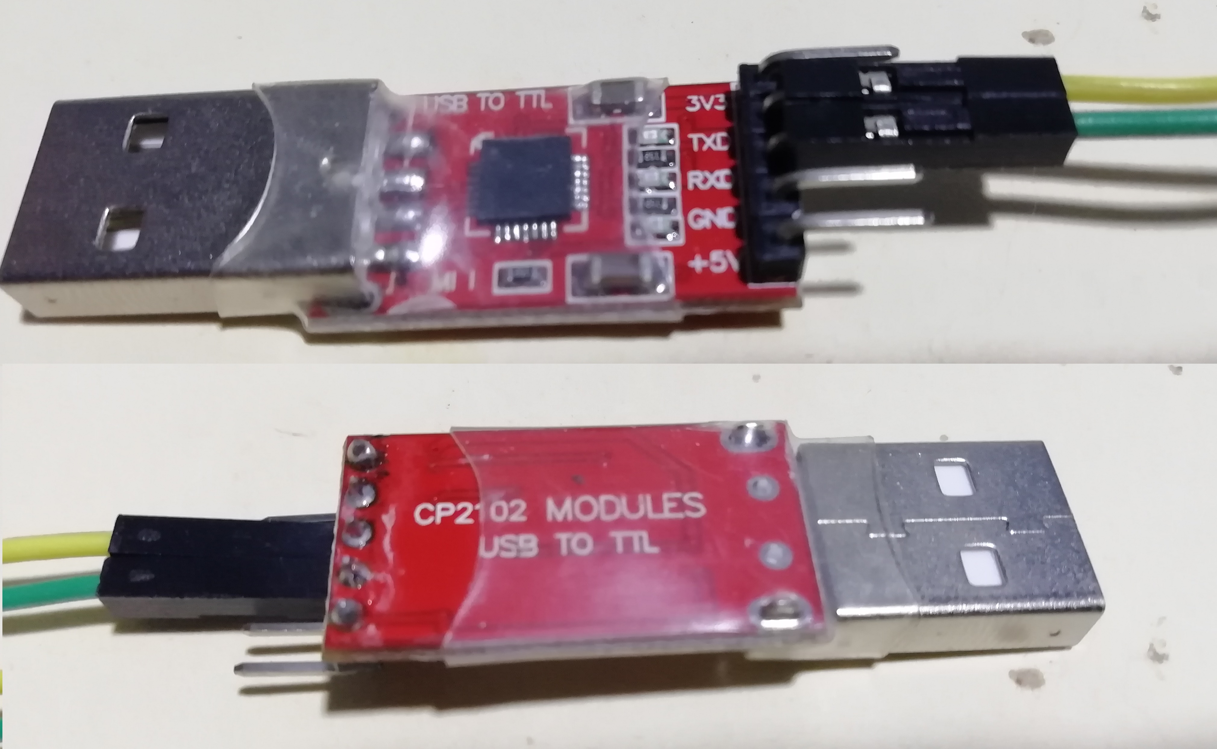
- Testing with the CP2102 USB to TTL converter module. Now I see the count in decimal.
- This is the converter I use. The CP2102 converter facilitates communication between the microcontroller and the PC using the USB protocol.
Useful links
- DATASHEET sensor SHARP GP2Y0A21
- DATASHEET sensor SHARP GP2Y0A41SK0F
- DATASHEET sensor Hall Effect A3144
- LabVIEW
Design Files
| Description | Files | |
|---|---|---|
| Efect_Holl_sensor_ATMega328 | Flame_sensor_ATMega328.ino | |
| Calibrado_SHARP_GP2Y0A21 | Calibrado_SHARP_GP2Y0A21.ino | |
| Sensor_SHARP_GP2Y0A21_Distancia | Sensor_SHARP_GP2Y0A21_Distancia.ino | |
| Server_WEB_Wemos_D1_BLINK_LED | Server_WEB_Wemos_D1_BLINK_LED.ino | |
| Efect_Holl_sensor_ATMega328_LabVIEW.vi | Flame_sensor_ATMega328_LabVIEW.vi | |
| Distance_sensor_SHARP 2Y0A21_ATMega328_LabVIEW | Distance_sensor_SHARP 2Y0A21_ATMega328_LabVIEW.vi | |
| Hello ATTiny44.ino | Hello_ATTiny44_ISP_LabVIEW | |
| Hello_LabVIEW_ATTiny44.vi | Hello_LabVIEW_ATTiny44.vi |

This work is licensed under a Creative Commons Attribution 4.0 International License.