11. Output devices
Individual assignment:
- Add an output device to a microcontroller board you’ve designed, and program it to do something
Group assignment:
- Measure the power consumption of an output device
A. INDIVIDUAL ASSIGMENT
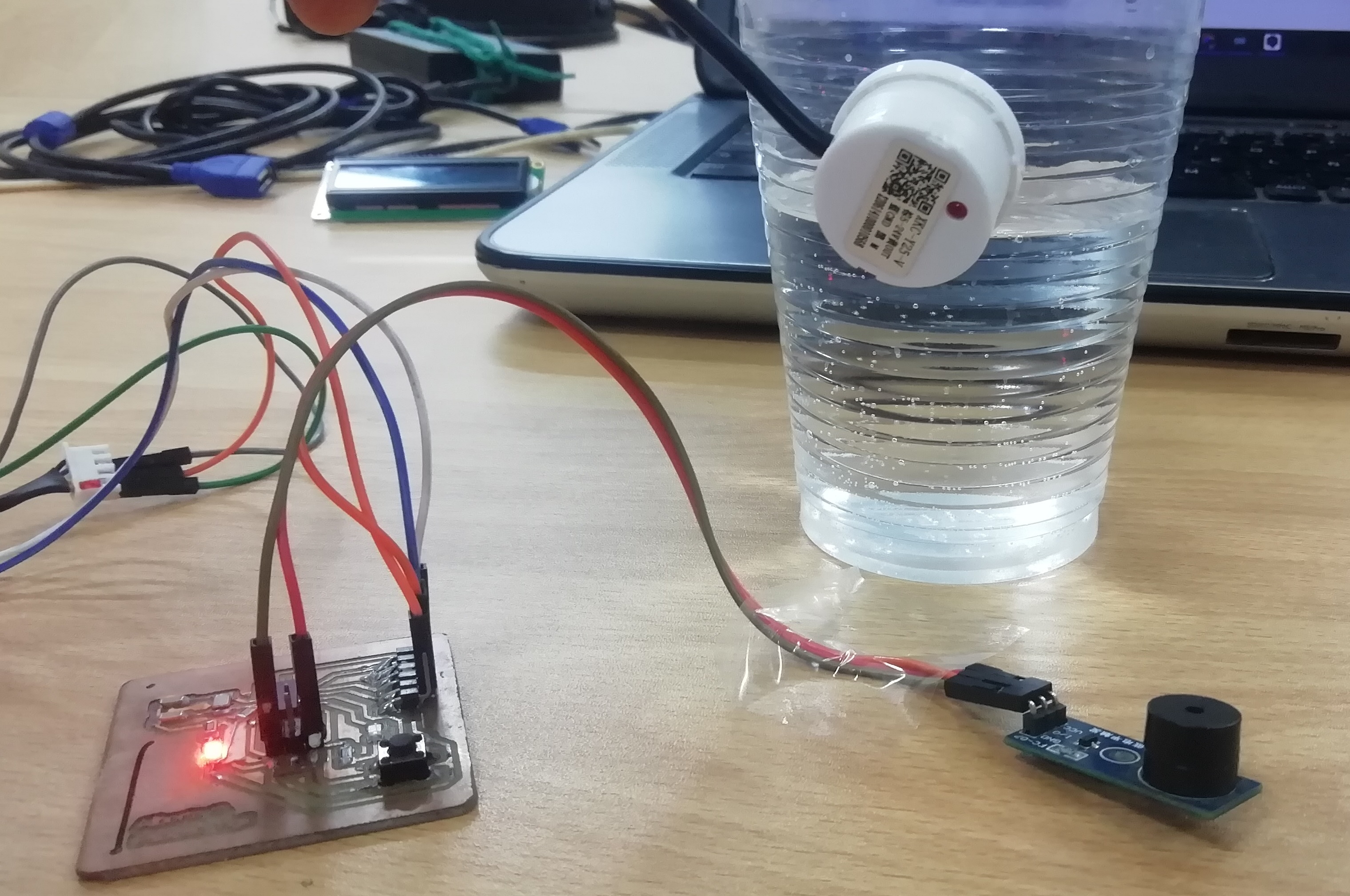
Doing something: water detector with audible warning:
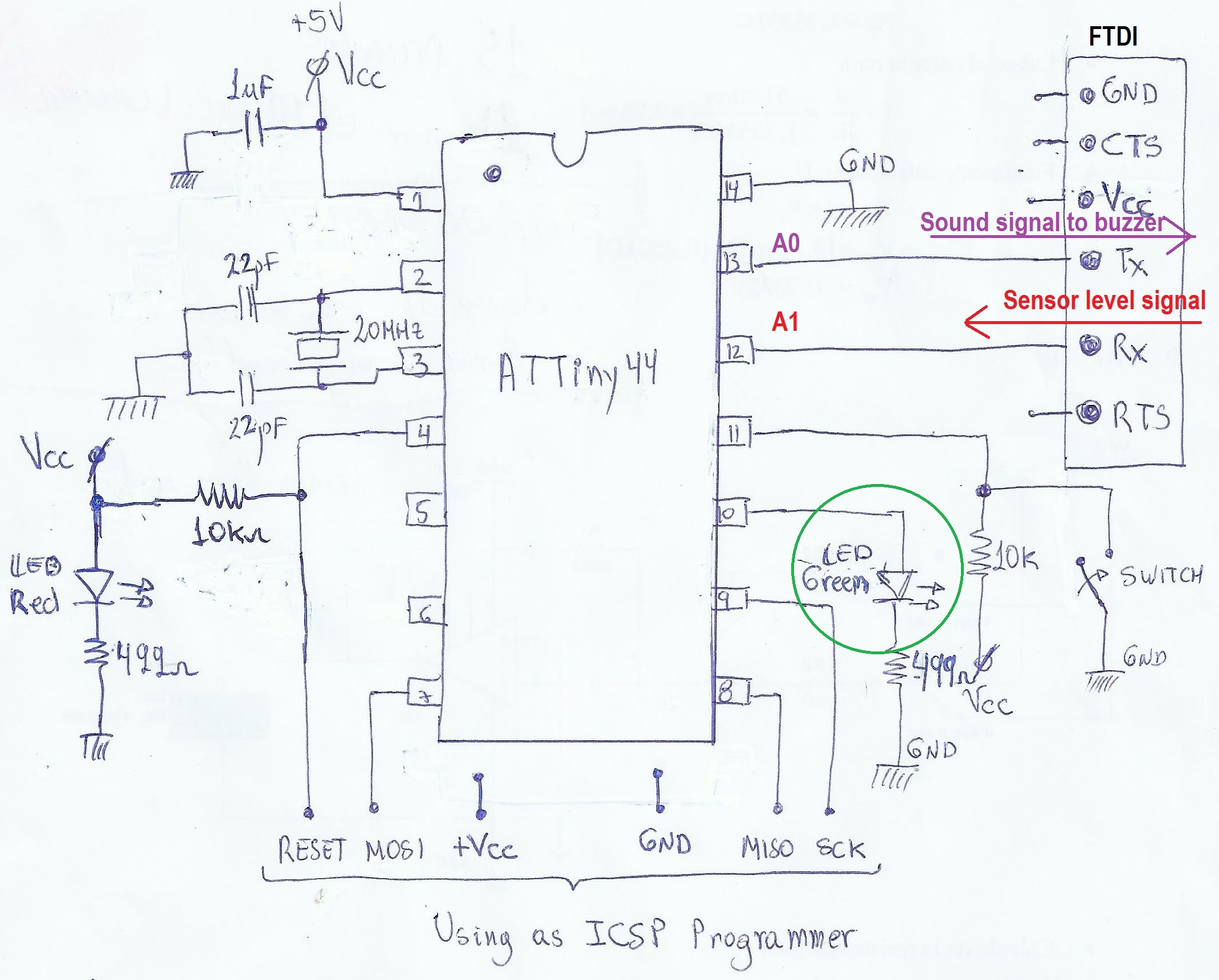
- I decided to make an audible detector (buzzer) when the liquid sensor detects the water in the bottle. For this I use the Board Hello_ATTiny44 manufactured in the assignment 7 Electronic design. The sensor signal is processed by the ATTiny44, then it sends a signal to the output device, in this case a small buzzer. A schematic is shown:
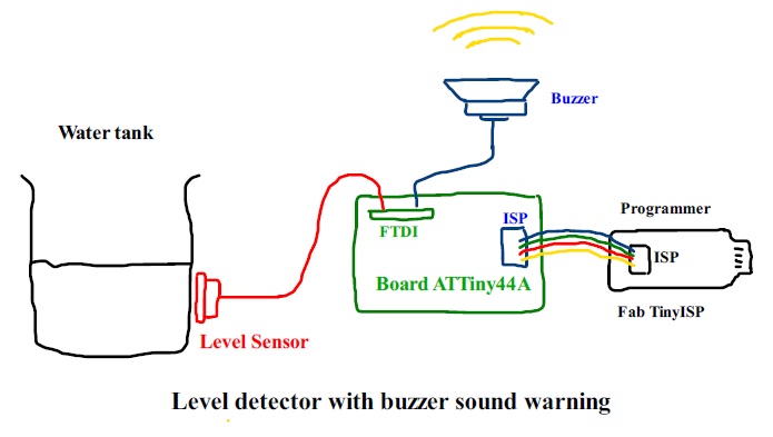
- The connection diagram (refer to the assignment 7.Electronic design) to the buzzer and the liquid sensor is shown in the picture:
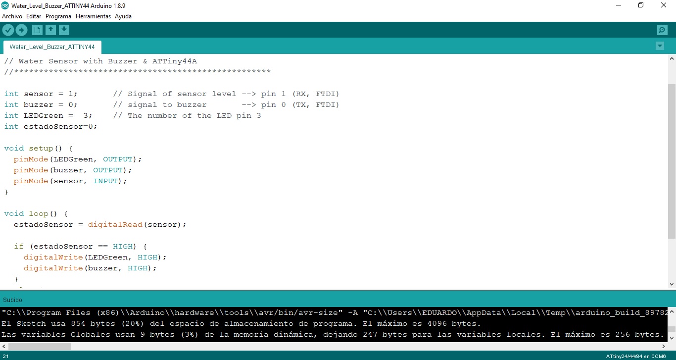
- The program in the arduino IDE is as follows:
//****************************************************
// Alberto E. Cohaila B. - FabAcademy 2022
//****************************************************
// Water Sensor with Buzzer & ATTiny44A
//****************************************************

int sensor = 1;       // Signal of sensor level --> pin 1 (RX, FTDI)
int buzzer = 0;       // signal to buzzer       --> pin 0 (TX, FTDI)
int LEDGreen =  3;    // The number of the LED pin 3
int estadoSensor=0;

void setup() {
  pinMode(LEDGreen, OUTPUT);
  pinMode(buzzer, OUTPUT);
  pinMode(sensor, INPUT);
}

void loop() {
  estadoSensor = digitalRead(sensor);

  if (estadoSensor == HIGH) {
    digitalWrite(LEDGreen, HIGH);
    digitalWrite(buzzer, LOW);
  }
  else {
    digitalWrite(LEDGreen, LOW);
    digitalWrite(buzzer, HIGH);
  }
  delay(10);
}
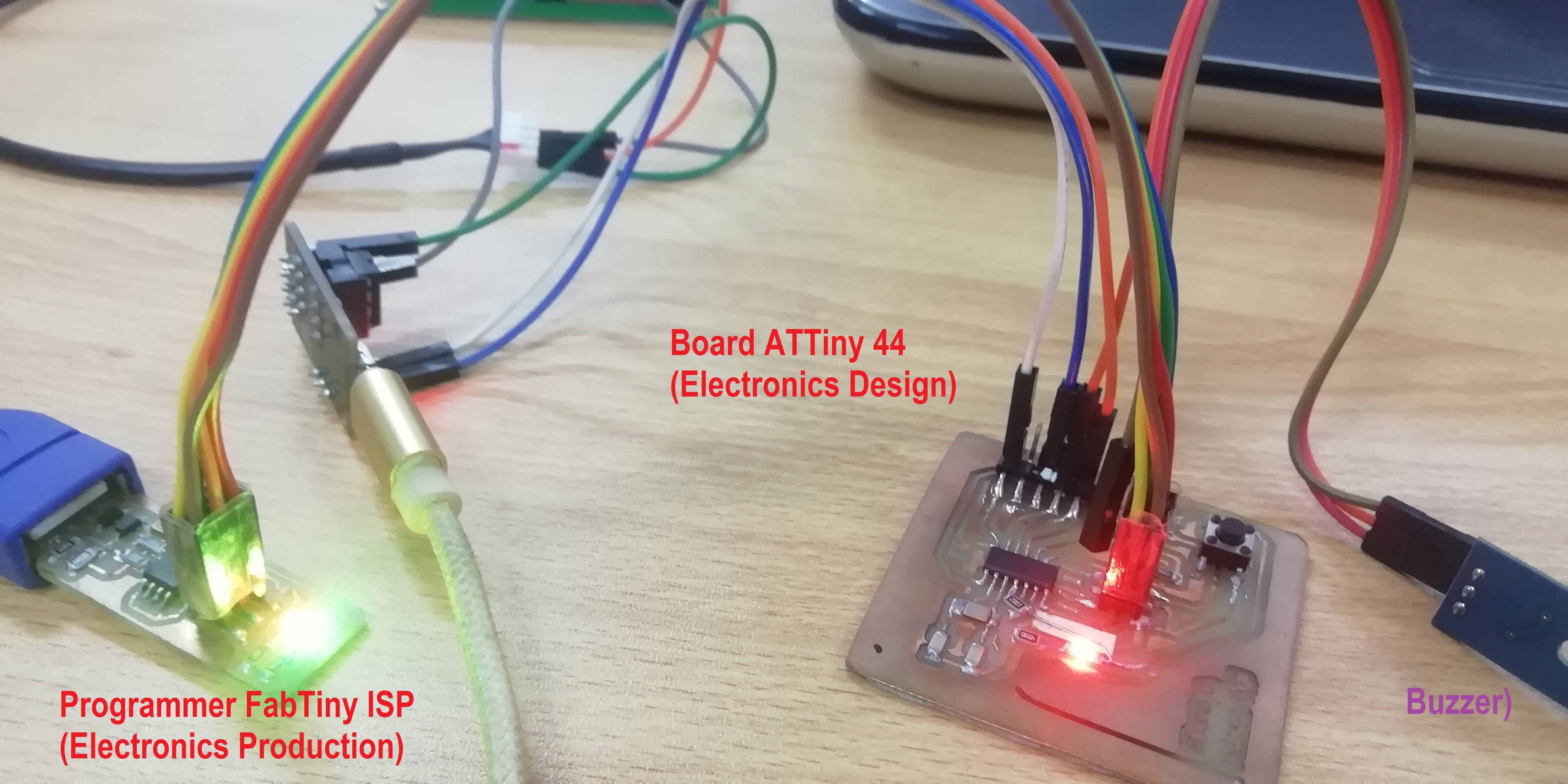
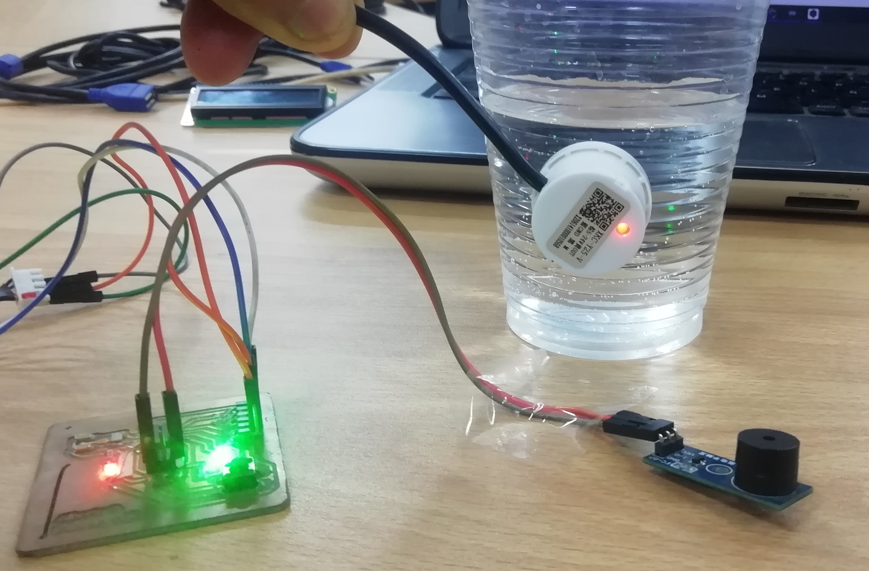
- I connect the programmer with the card and transfer it to the ATTiny44 memory, it does not give me any errors. When the green led lights up, it indicates that the program is being transferred.
- The sensor does not detect water, so the buzzer does not beep.
- When the sensor detects water, the buzzer beeps constantly.
- Here you can see the hero video:
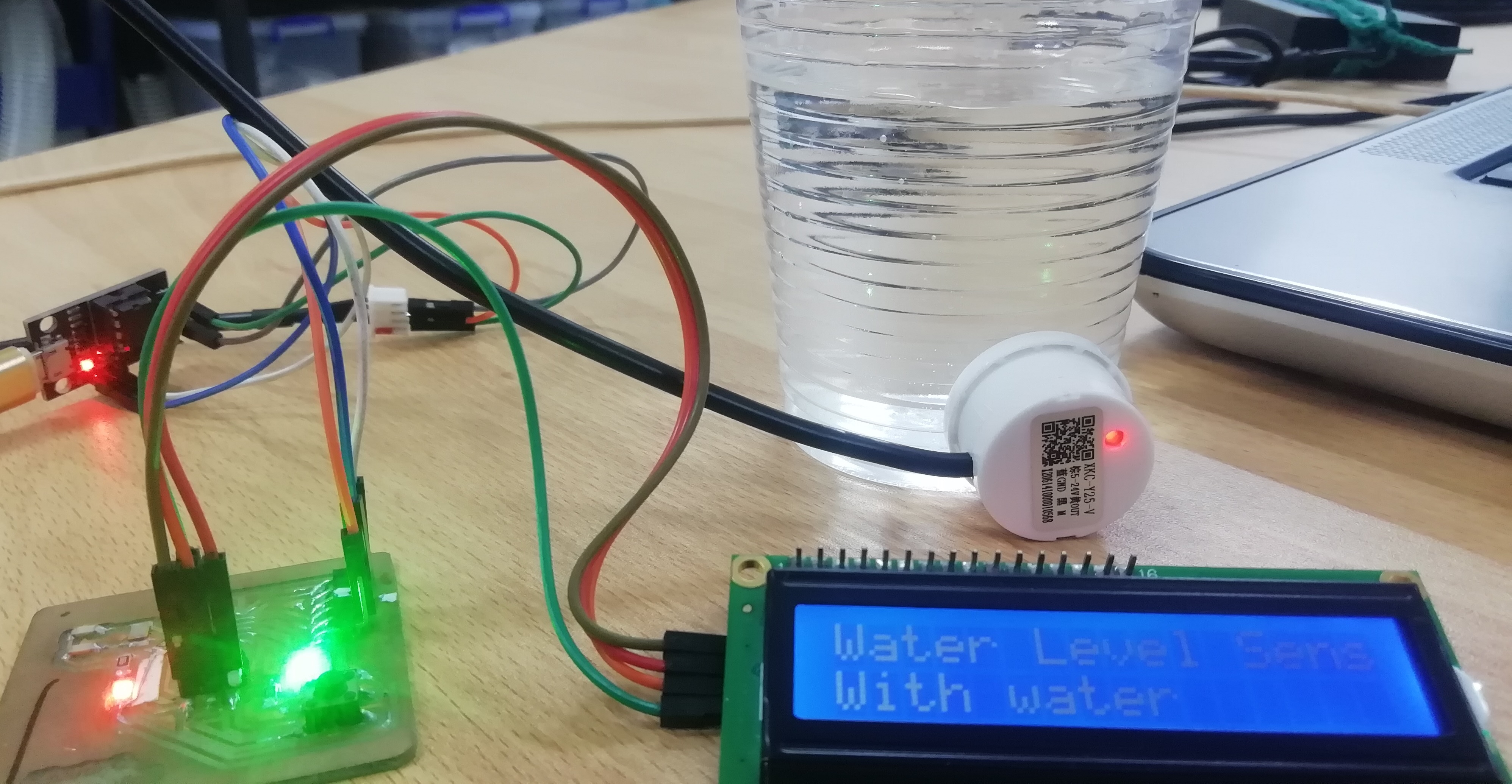
Output LCD 16x2:
- In Embedded programming week, I made a program to display data on a 16x2 LCD using the I2C connection. Using I2C with the LCD saves me a lot of pins, it only uses 2 data transfer pins and two 5 V power pins.
I2C: What is it?
-
I2C is a serial communication port and protocol, it defines the data frame and physical connections to transfer bits between 2 digital devices. The port includes two communication wires, SDA and SCL. In addition, the protocol allows up to 127 slave devices to be connected to these two lines, with speeds of up to 100, 400 and 1000 kbits/s. It is also known as IIC or TWI - Two Wire Interface.
-
The I2C protocol is one of the most used to communicate with digital sensors, because unlike the Serial port, its architecture allows to have a confirmation of the received data, within the same frame, among other advantages.
-
The connection of so many devices to the same bus, is one of the main advantages. In addition, if we compare I2C with another serial protocol, such as Serial TTL, this one includes more bits in its communication frame that allows sending more complete and detailed messages.
-
The messages sent through an I2C port include, in addition to the information byte, an address of both the register and the sensor. For the information that is sent there is always a confirmation of receipt by the device. For this reason it is good to differentiate the different elements involved in this type of communication.
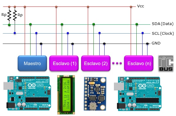
I2C: Communication scheme and elements:
Whenever we talk about oral communication, it is understood that it is between two or more people. As a consequence, we can also indicate that in a digital communication there are different devices or elements. In the case of I2C there are two basic elements, a MASTER and a SLAVE. Figure 1 shows a typical connection of three devices, the bus consists of two lines called, Serial DAta - SDA and Serial CLock - SCL. That is, Serial Data and Serial Clock. In particular, two pull-up resistors, between 2.2K and 10K, are connected to the bus.
- This is a video showing the operation of the LCD as a output:
B. GROUP ASSIGNMENT
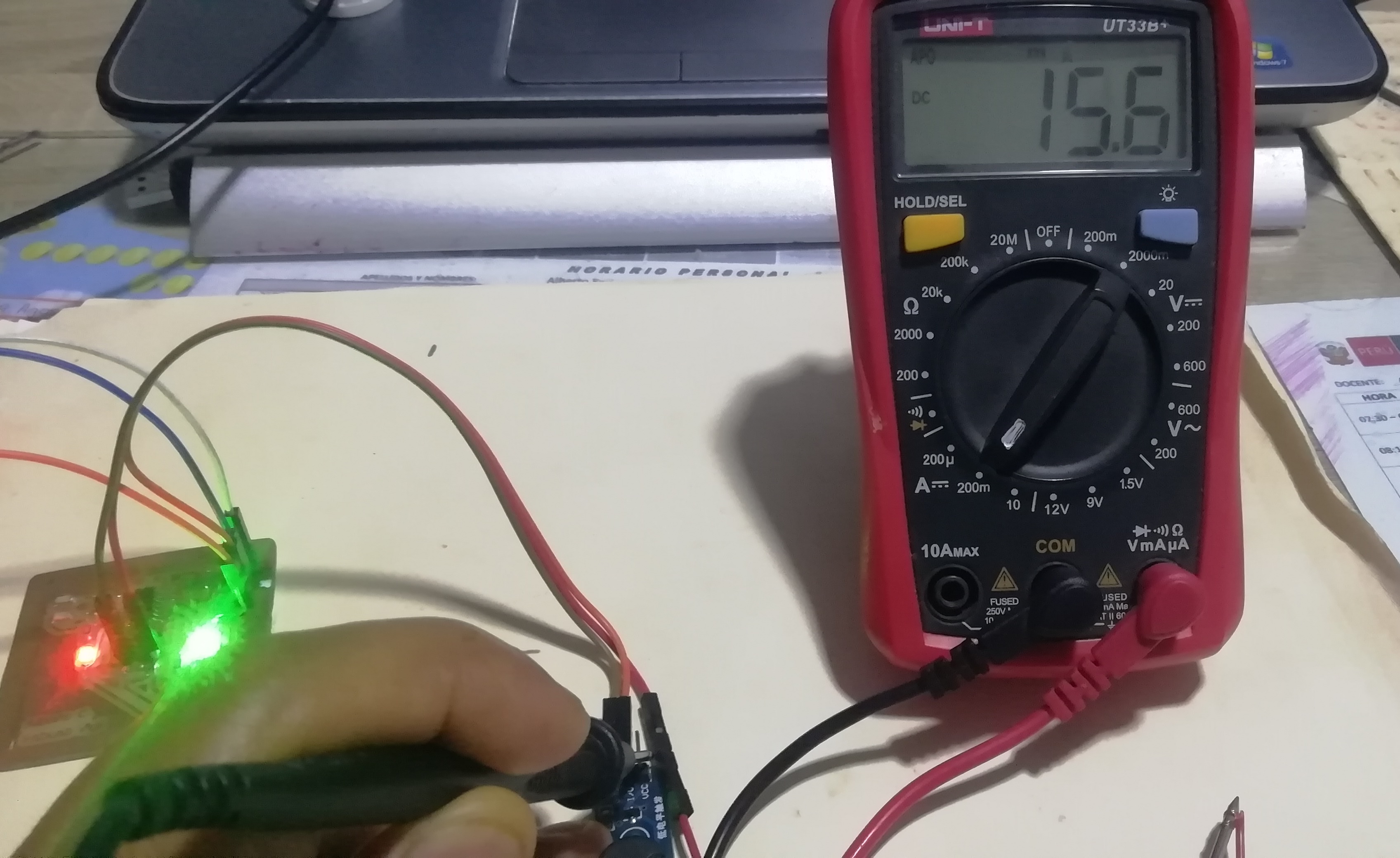
-
To measure the consumption expressed in watts of the buzzer, I must measure the current and voltage. Then the power will be P=V.I Watts.
-
Measuring the current: The current is measured in series with the load. The current must be measured when the buzzer sounds.
- Voltage measurement: The voltage is measured in parallel with the load. The voltage should be measured when the buzzer sounds.
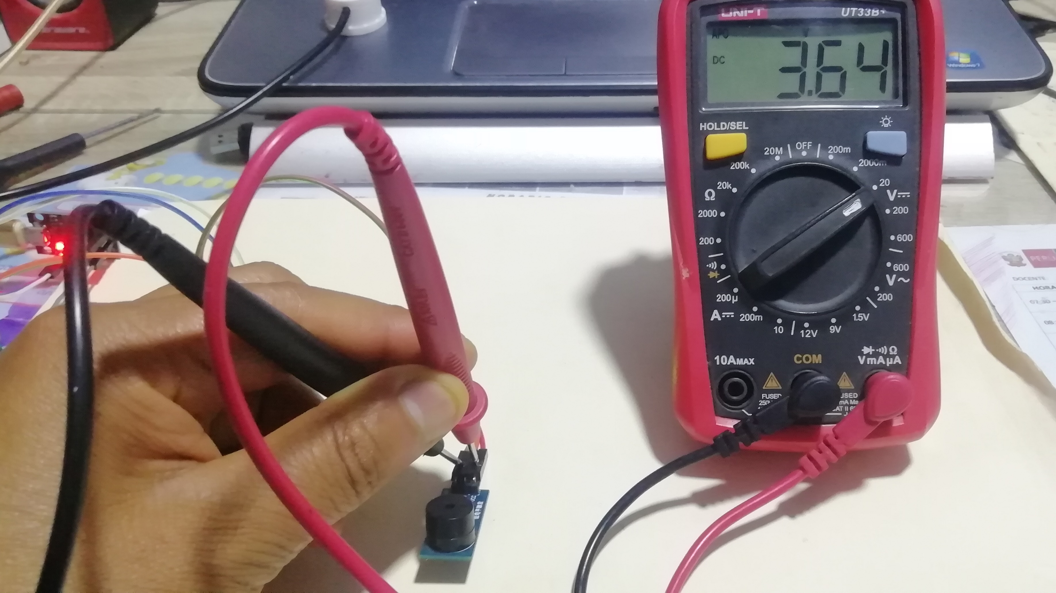
- These are the results:
//****************************************************
Current = 15,6 mA
Tension = 3,65 V
//****************************************************
Potencia = 15.6 * 3.6
Potencia = 56,16 mW
//****************************************************
- I conclude that the power consumption of the buzzer is very low, that is why a small watch battery is enough to activate it.
Design Files
| Description | Files | |
|---|---|---|
| Water_Level_Buzzer_ATTINY44 | Water_Level_Buzzer_ATTINY44.ino |