12. Mechanical design, machine design
Our Team
My team was made up as follows:
-
Ulises who is my instructor
-
Alberto, student Fabacademy 2022
-
Guadalupe, student Fabacademy 2022
Ulises first carried out the search for the data sheets of the components to be used, such as electrical characteristics, mechanical dimensions, modes of operation and in the final part he was in charge of the assembly and function test of the system.
I, Alberto, first made the design of the structure considering the mechanical dimensions of the selected components, then I made the design of the printed circuits considering the electrical characteristics of each component and finally I developed the control programs in manual and automatic mode. I also laser cut the parts and assembled the design. What we had problems was that the belt was turning with friction, we solved it by placing a long bushing in the end pulley.
Guadalupe, I explained to her how it should look and I gave her the idea of the hand drawn design, she made the CAD in Onshape.
Group Work Link
Here Start my Individual Work
INDIVIDUAL ASSIGNMENTS
-
Document your individual contribution.
-
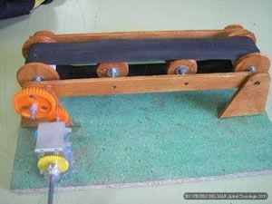
A conveyor belt model was searched on the internet and we found a very simple and necessary one for what we wanted to make it.
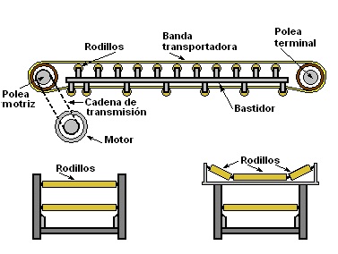
- The components of the conveyor belts can be seen in the following image:
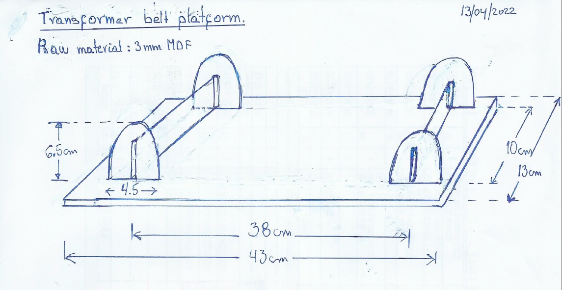
- A trace was made on paper to define its dimensions:
- Based on the image and the manual tracing, the strip was designed in the Onshape software.
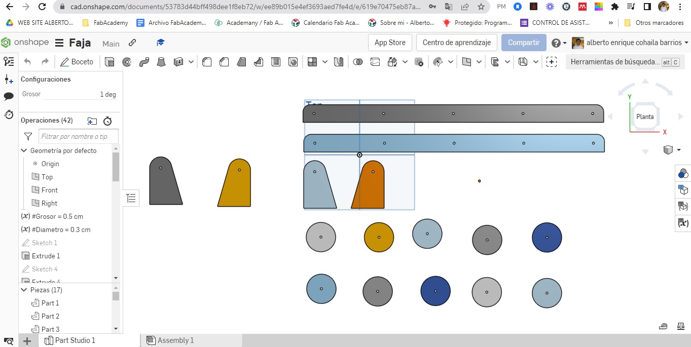
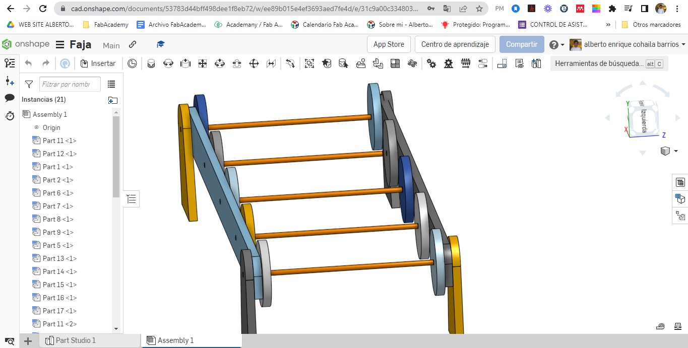
- Obtaining as final product the following:
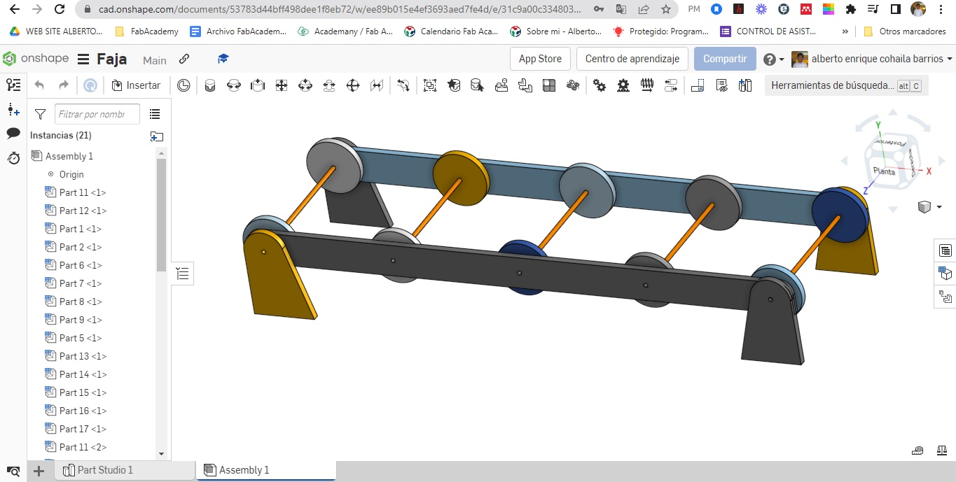
- Looking at it from different angles:
- We use 3mm MDF and make the cuts on the laser cutting machine.
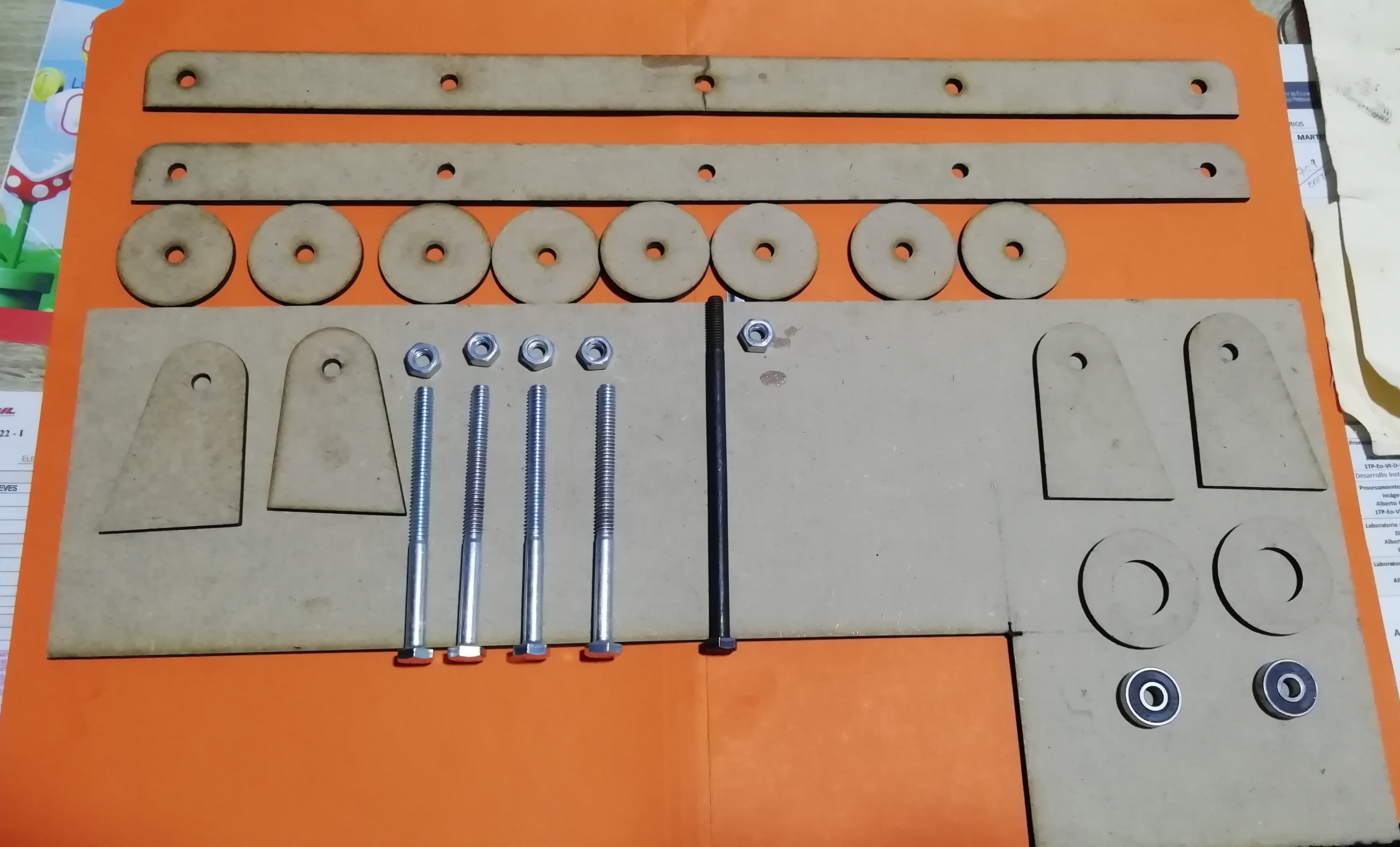
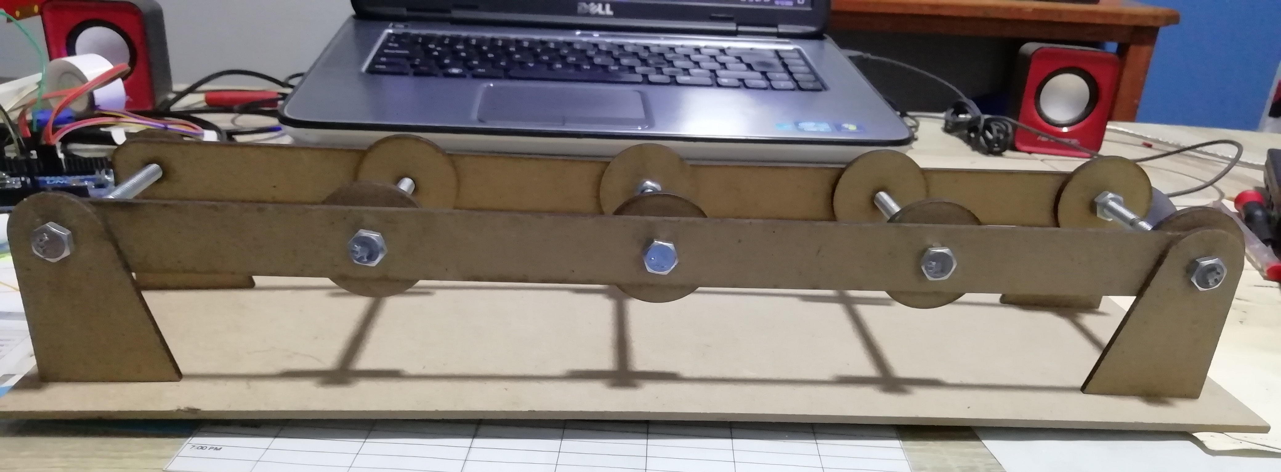
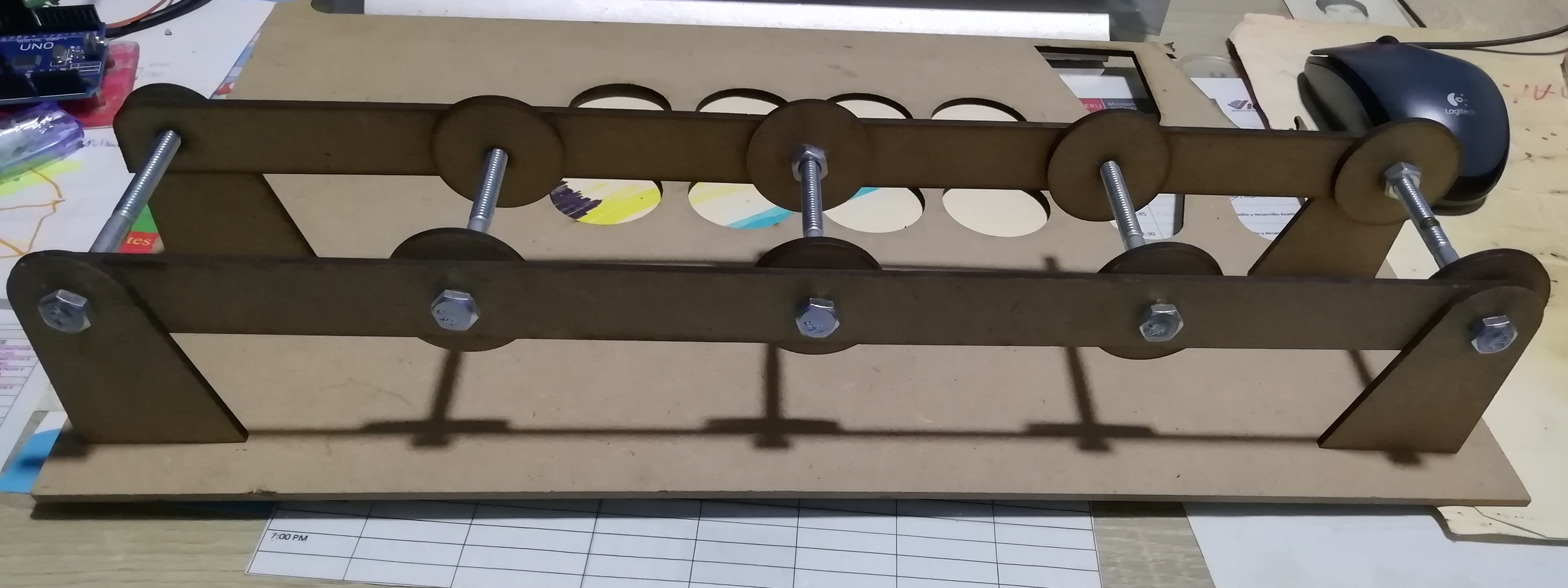
- Assembling this is how it looks like:
- For the rollers we use 1/4 inch PVC pipe.
- For the motor shaft roller we line it with sandpaper so that it can pull the belt..
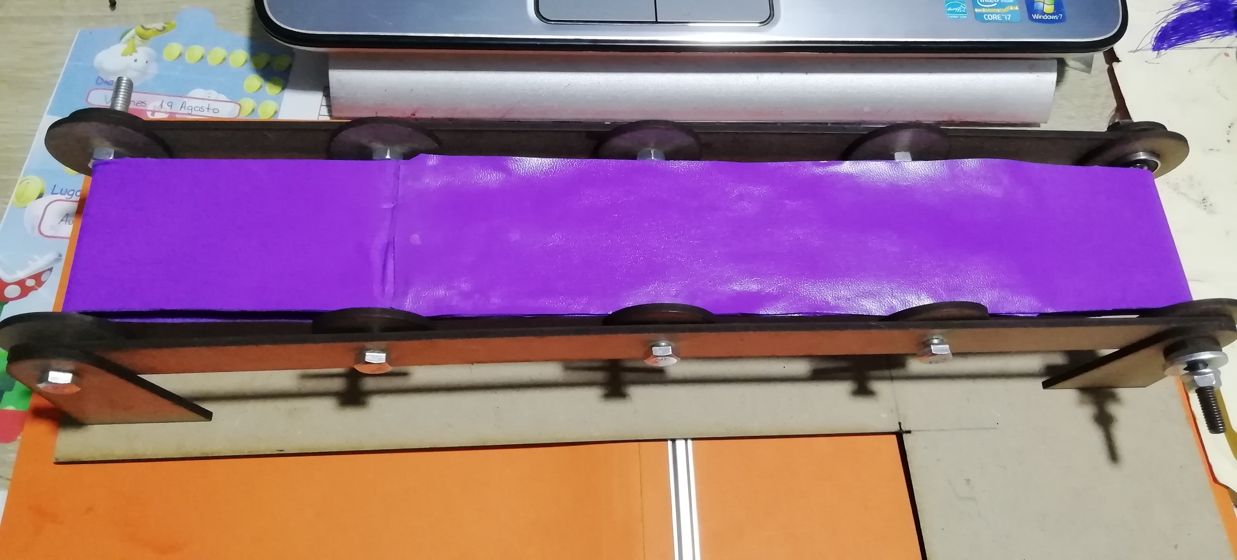
- For the conveyor belt we use corrospum, the rough element is placed inside, the smooth part outside.
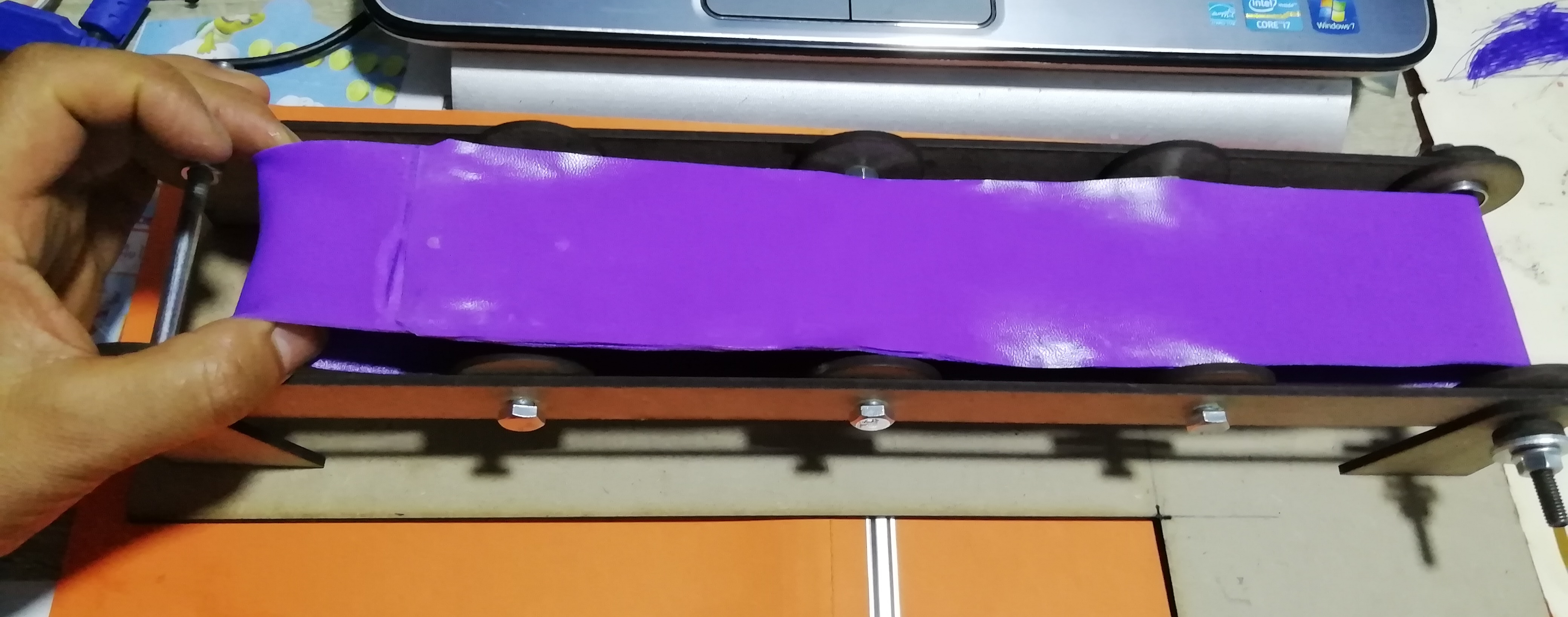
- Then, this is how the transprtator band looks like to me.
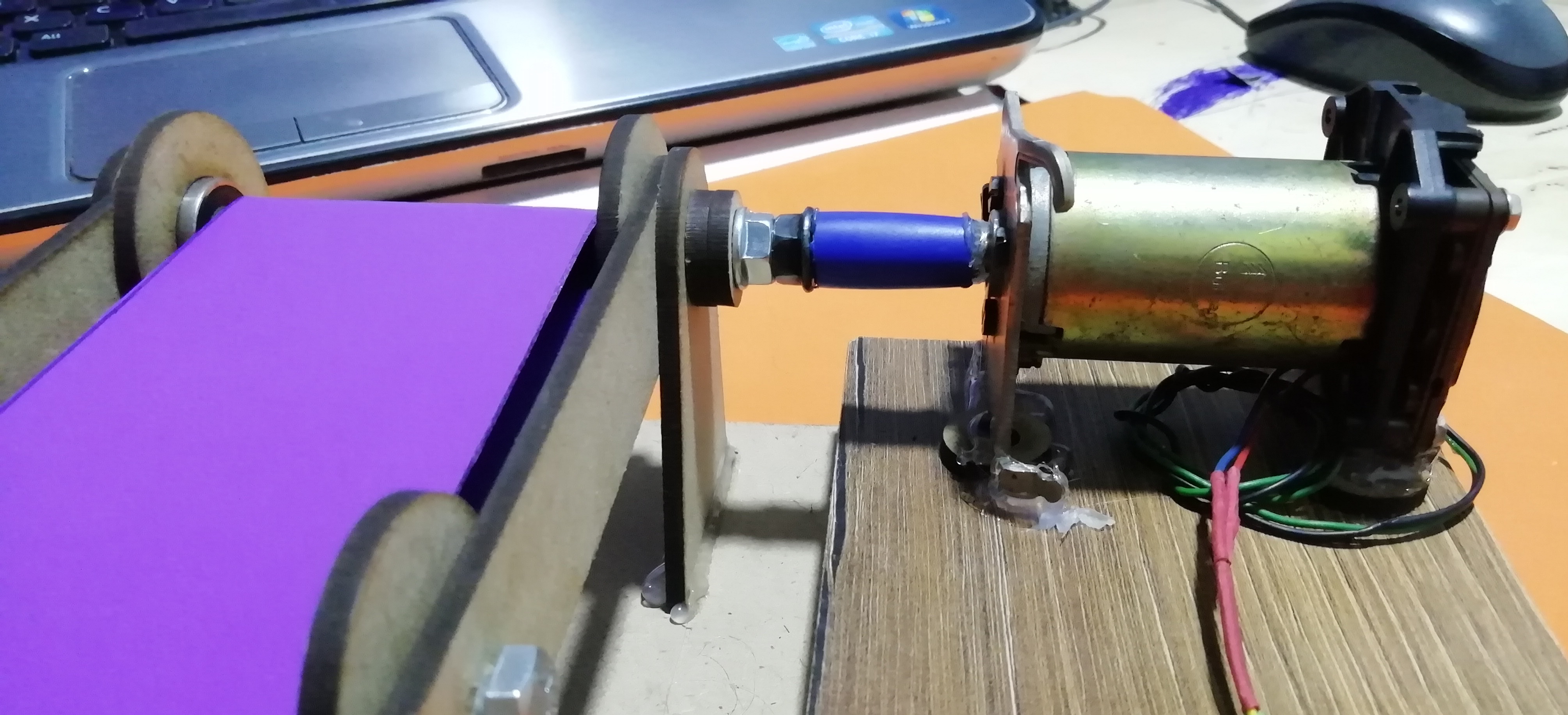
- To couple the drive pulley and the DC motor, a timing belt should have been used first, but since it was not available, corrospum was cut and did not work.
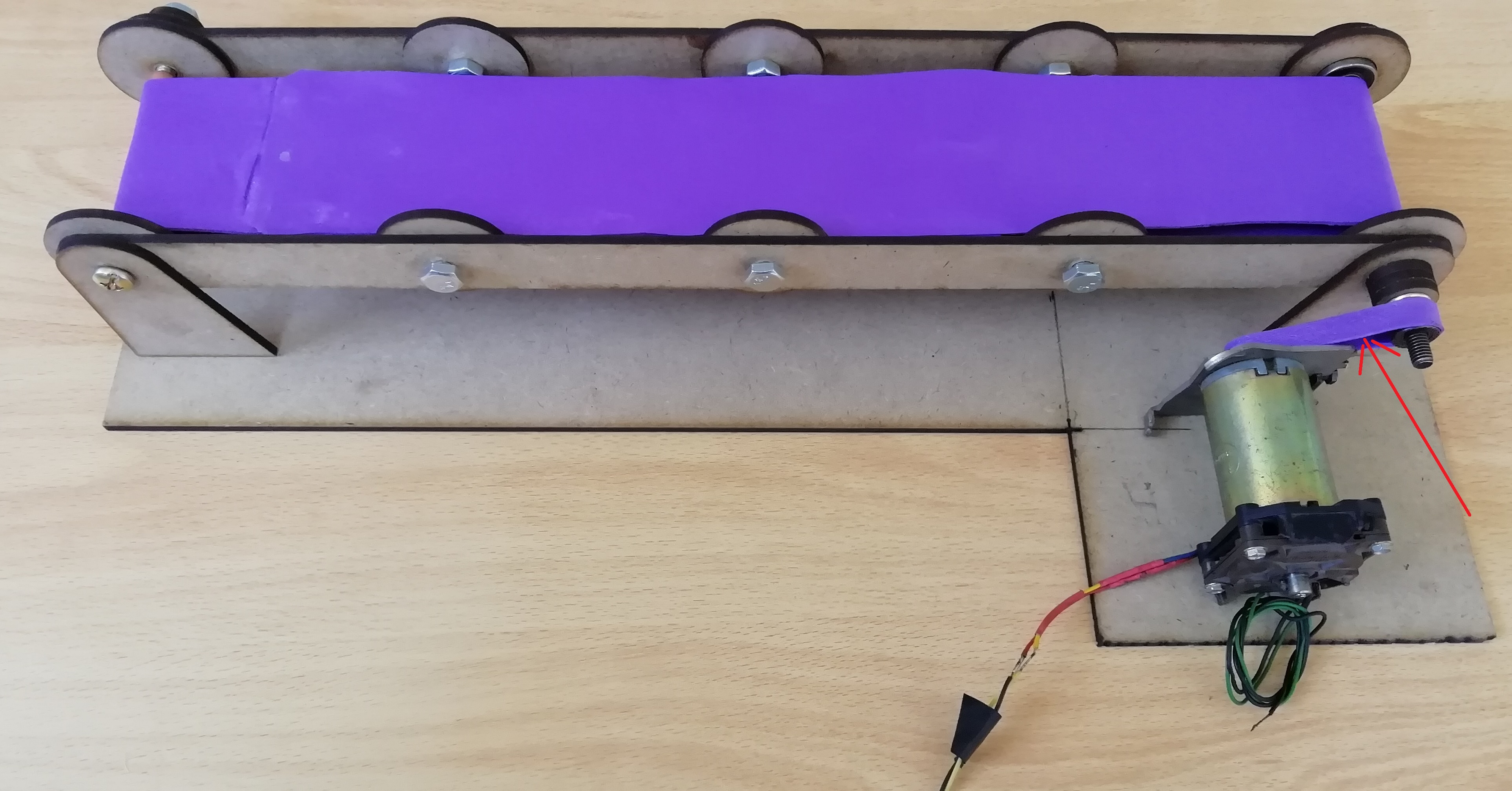
- Directly coupled to the drive roller shaft with the motor.
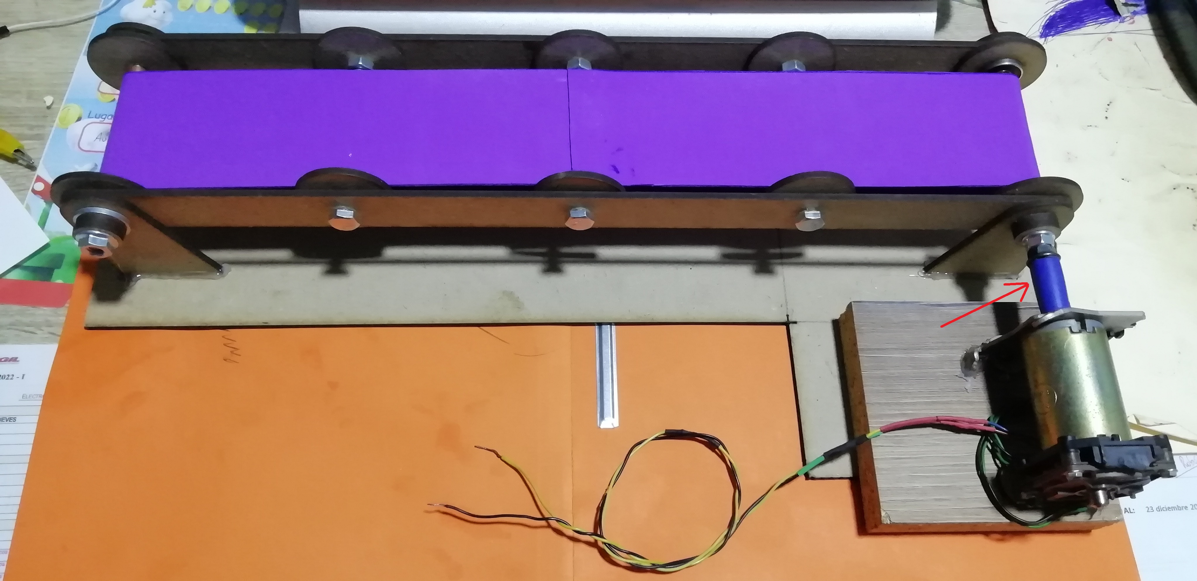
- This is a side view of what it looks like:
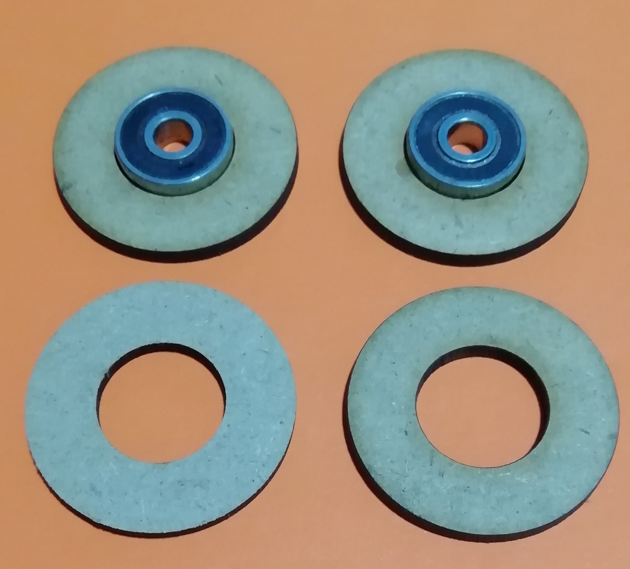
- This is the process of laser cutting the circles of the drive shaft bearings:
- This is a video of the placement of the bearings in the circle:
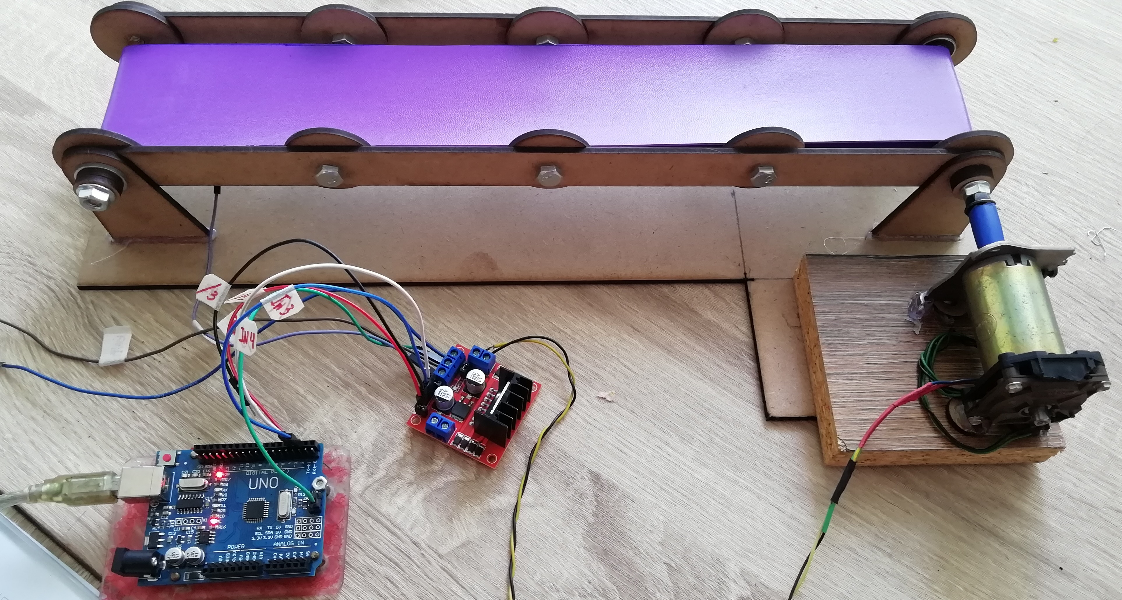
Conveyor Belt Manufacturing Testing
- To improve the conveyor belt and automate it, I am going to add a program that moves the belt to the right, then to the left and stops, so it repeats the sequence automatically. The ATmega328 will be used as the automation controller. A current driver drives the belt motor, since the 10 mA current of the ATmega328 is not enough.
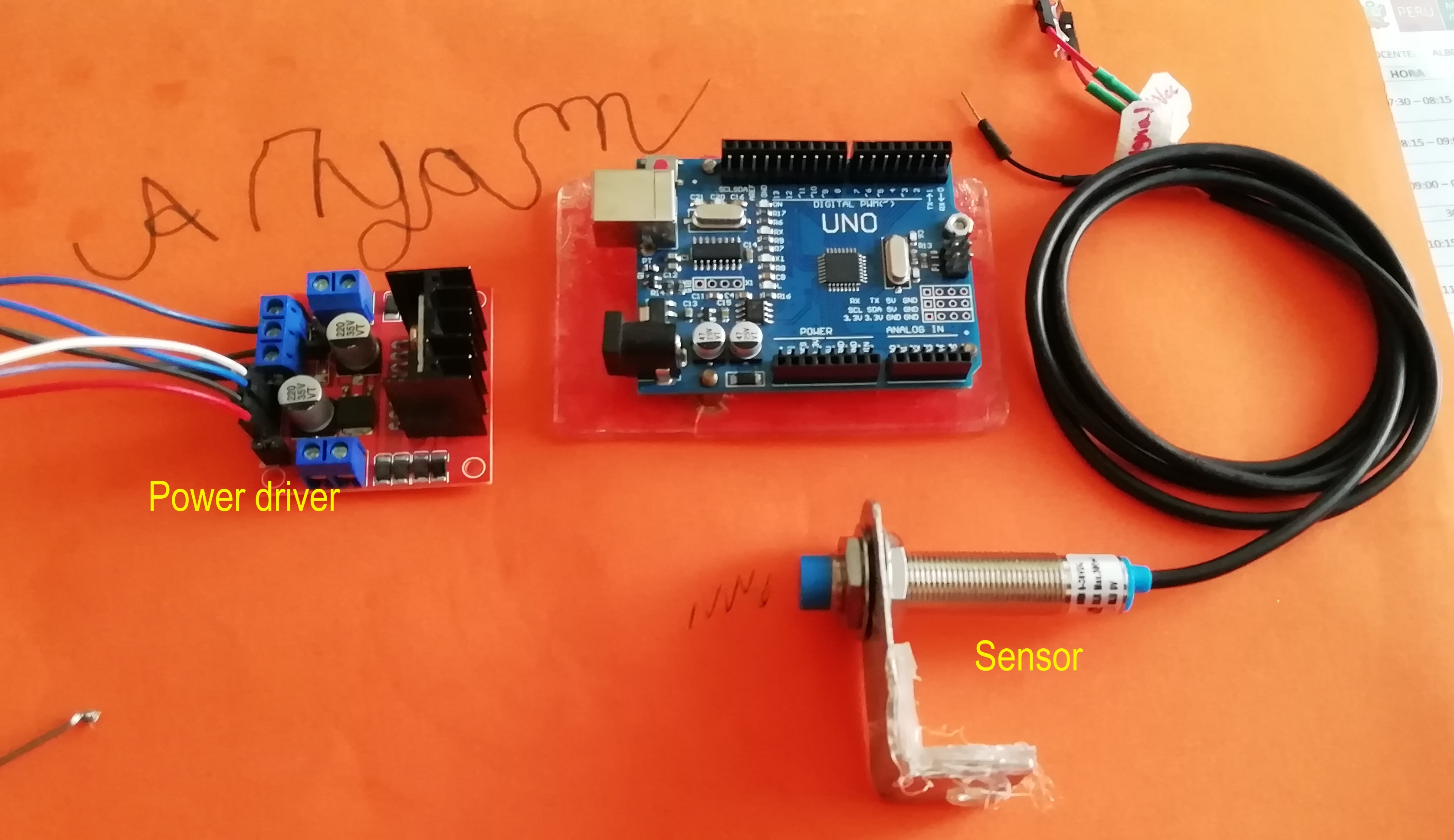
Manufacturing
The materials to be used are the L298N driver and the ATMega328P microcontroller.
Software
- What the program does is that the conveyor belt moves 5 min to the right, then 5 min to the left, then stops for 5 min. This sequence is repeated successively.
/* ****************************************************
   Conveyor Belt - LabVIEW
   ****************************************************
   The conveyor belt moves 5 min to the right, then 5 min to the left,
   then stops for 5 min and so on.
   Pinout:
   Right:
   IN1=1  -> OUT1= 12V
   IN2=0  -> OUT2= GND
   Left:
   IN1=1  -> OUT1= GND
   IN2=0  -> OUT2= 12V

  ****************************************************
  Alberto E. Cohaila B. - FabAcademy 2022
  ****************************************************
*/

int PinIN1 = 2;
int PinIN2 = 3;
int time = 5000;
void setup() {
  Serial.begin(9600);
  pinMode(PinIN1, OUTPUT);
  pinMode(PinIN2, OUTPUT);
}

void loop() {

  EngineRight();
  Serial.println("Clockwise Motor Rotation");
  delay(time);

  EngineLeft();
  Serial.println("Rotate the motor counterclockwise");
  delay(time);

  EngineStop();
  Serial.println("Engine Stopped");
  delay(time);
}

void EngineRight()
{
  digitalWrite (PinIN1, HIGH);
  digitalWrite (PinIN2, LOW);
}
void EngineLeft()
{
  digitalWrite (PinIN1, LOW);
  digitalWrite (PinIN2, HIGH);
}

void EngineStop()
{
  digitalWrite (PinIN1, LOW);
  digitalWrite (PinIN2, LOW);
}
Tests
- Watch the video where the conveyor belt moves to the left, then to the right, stops and so on.
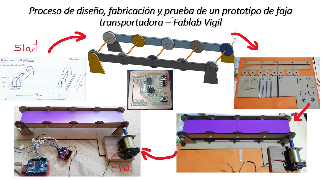
Summary
- A summary of the Mechanical Design, Machine Design process is shown in the following slide:
Design Files
| Description | Files | |
|---|---|---|
| Program Conveyor belt | ConveyorBelt.ino | |
| Laser cuttingr_bearing | RUEDA.rld | |
| Laser cuttingr_bearing2 | RUEDA2.rld |