9. Embedded programming
This week I worked on:
Individual assignment:
- Read a microcontroller data sheet.
- Program your board to do something with as many different programming languages and programming environments as possible
Group assignment:
- Compare the performance and development workflows for other architectures
A. INDIVIDUAL ASSIGMENT
Data sheet:
- Use the ATMega328P microcontroller data sheet, which I downloaded from the official Microchip website.
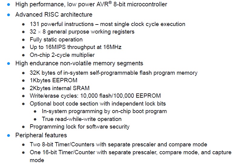
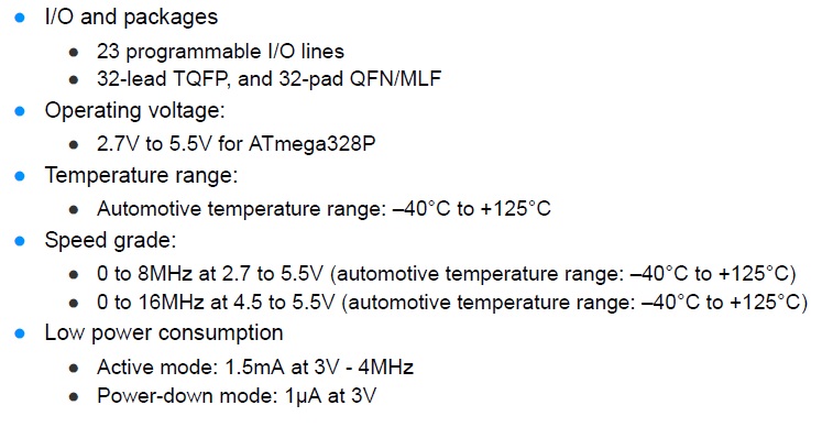
- Interesting fact is the voltage voltage is from 2.7 V to 5.5 V.
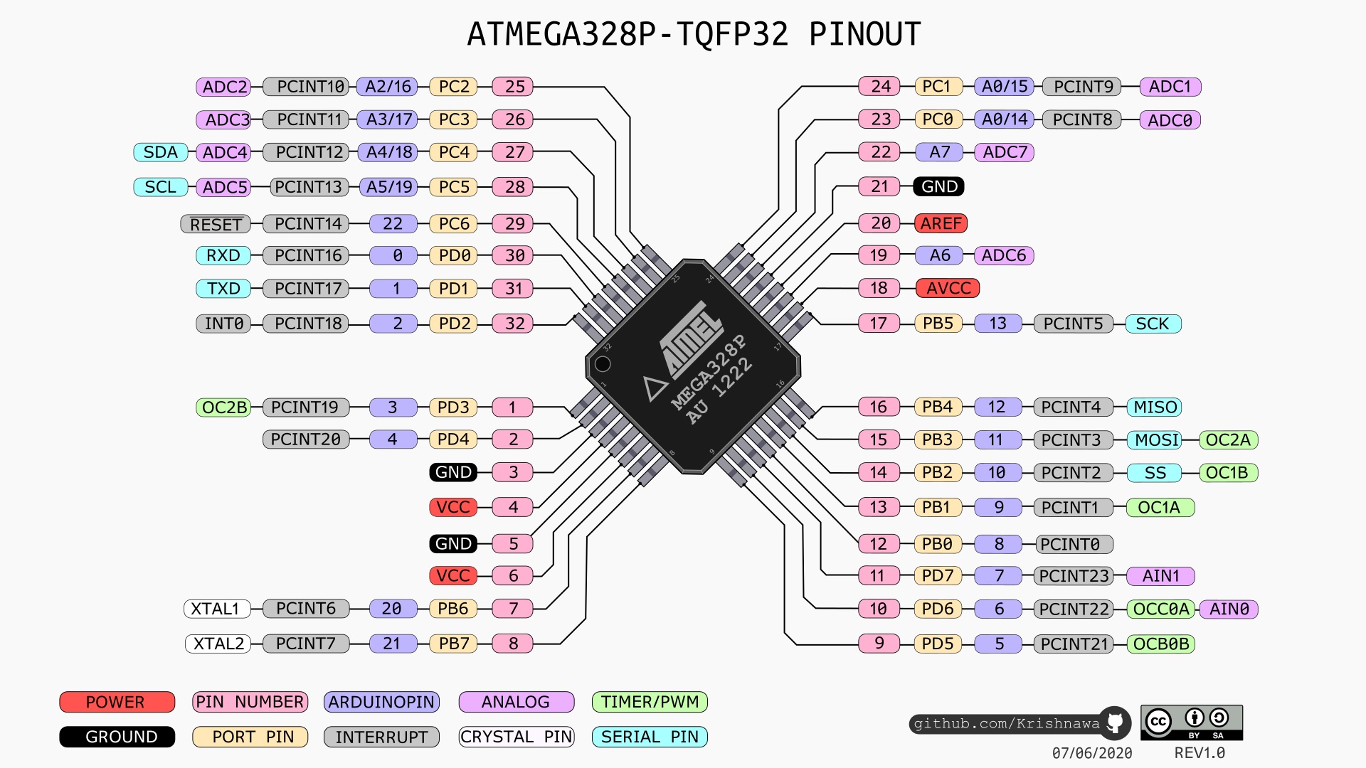
- Regarding the pins, this has 32 pins for the case of the SMD model.
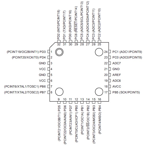
- ATMega328P PinOut:
AVR y ATTiny:
-
AVR is a family of microcontrollers developed since 1996 by Atmel, acquired by Microchip Technology in 2016. These are modified Harvard architecture 8-bit RISC single-chip microcontrollers. AVR was one of the first microcontroller families to use on-chip flash memory for program storage, as opposed to one-time programmable ROM, EPROM, or EEPROM used by other microcontrollers at the time.
-
AVR microcontrollers find many applications as embedded systems. They are especially common in hobbyist and educational embedded applications, popularized by their inclusion in many of the Arduino line of open hardware development boards.
- I will use the Arduino IDE and the programmer Atmel-ICE to program the ATMega328P and the ATTiny44A.


- The Arduino IDE version I used is 1.8.9
- My question was how the Arduino IDE recognizes the ATMega328P microcontroller, if it does not appear in the list of cards.
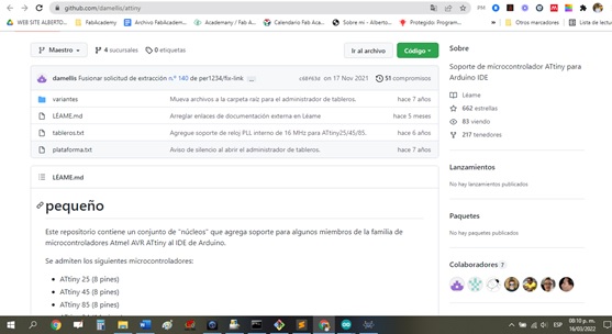
- Checking the web, I found how the card url manager for the ATtiny 45 works, the Github gave me a reliable result.

- I clicked on the first Google search
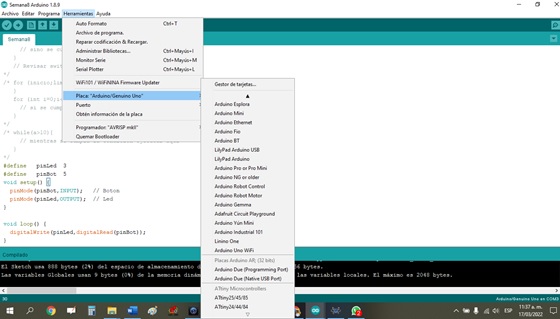
- Copy the link and paste it into the Arduino board manager, then OK.

- Then I can see the ATtiny family of microcontrollers in the Arduino IDE.
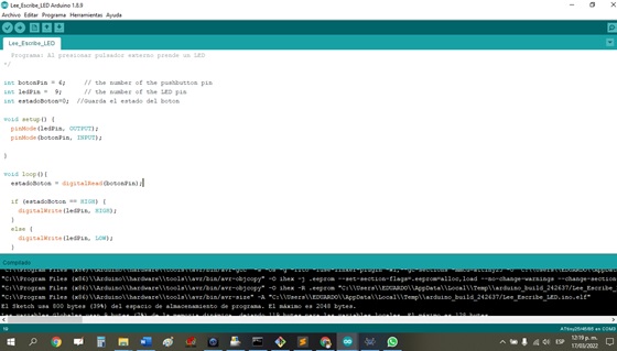
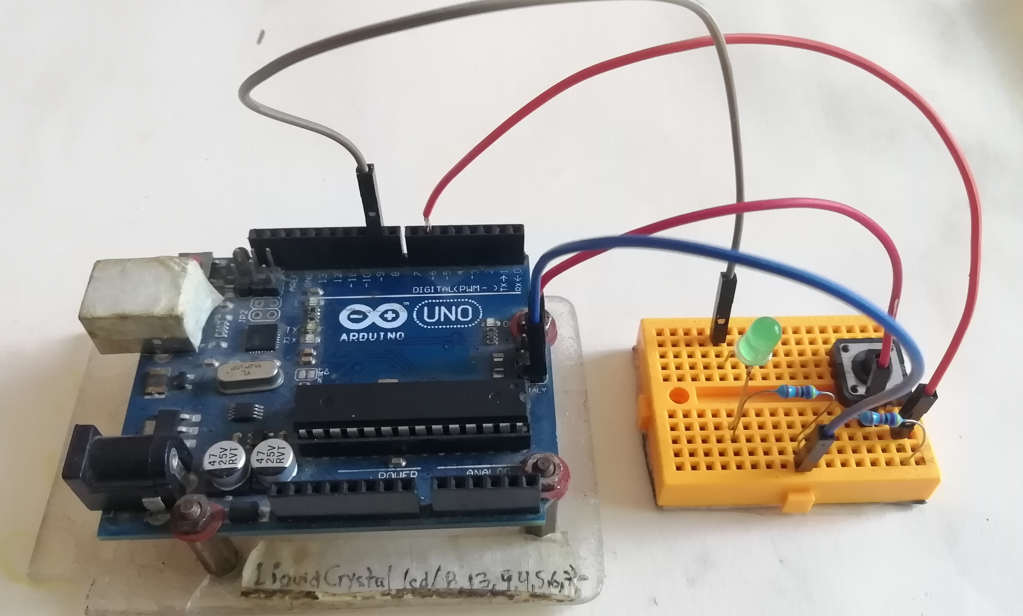
- Now, I am going to program the ATMega328P with an external button, so that when it is pressed, an LED flashes with a delay of 1sec. I press the button again and turn off the LED, and so on.
/*Desig: Alberto E. Cohaila Barrios
  IES FPGV
  FabLAB Vigil
  Microcontrolador AVR, 8 bits: ATMega328P
  Program: Pressing an external button turns on an LED
*/

int botonPin = 6;     // the number of the pushbutton pin
int ledPin =  9;      // the number of the LED pin
int estadoBoton=0;  //Guarda el estado del boton

void setup() {
  pinMode(ledPin, OUTPUT);
  pinMode(botonPin, INPUT);
}

void loop(){
  estadoBoton = digitalRead(botonPin);

  if (estadoBoton == HIGH) {
    digitalWrite(ledPin, HIGH);
  }
  else {
    digitalWrite(ledPin, LOW);
  }
  delay(50);
}
- I select the board: Arduino
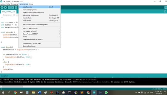
- Then I compile and verify that it is successful.
- Then I transfer the low level file (Hex format) to the ATMega328P
- I verify that it works, which is a good experience for me. You can see a video here:
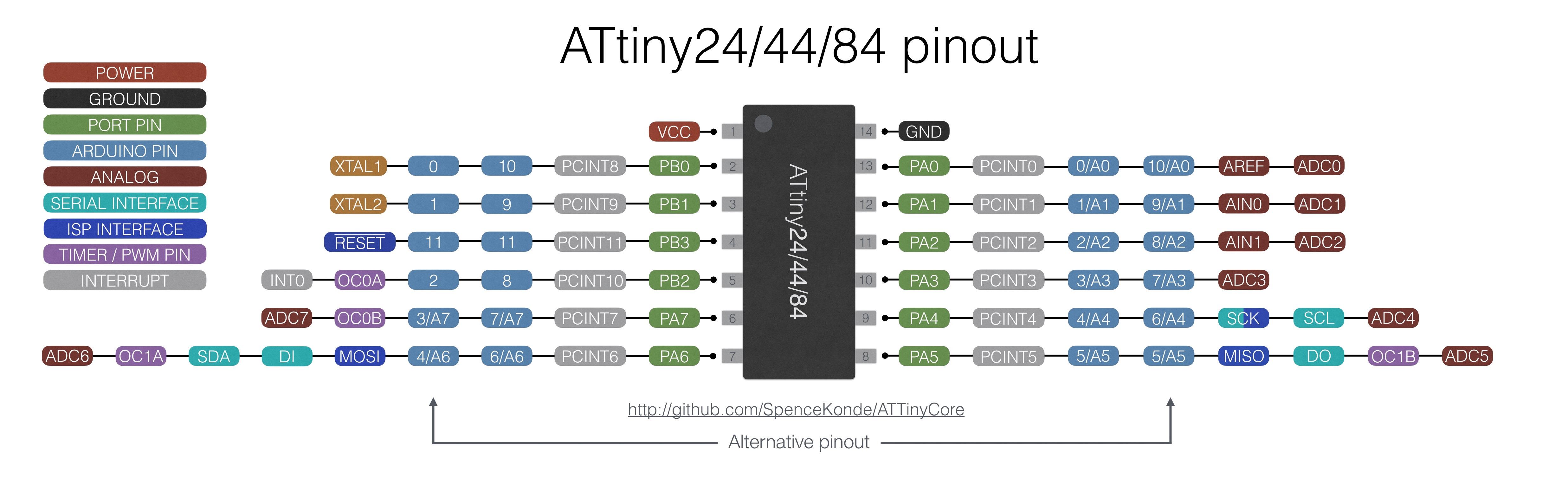
Doing something: ATTiny44A, LCD and protocol I2C
I2C:
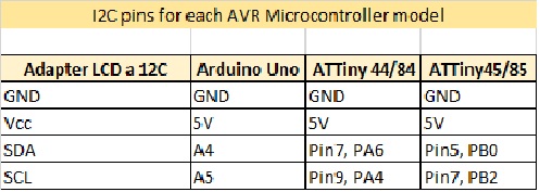
The attiny 24/44/84 can communicate I2C on PB2 (pin 7) (SCL) and PB0 (pin 5) (SDA). The ‘Wire’ library that is used to read and write bytes from and to the I2C port on the arduino doesnt work on the attiny. It needs the TinyWireM library to act as an I2C master
- Necessary devices:
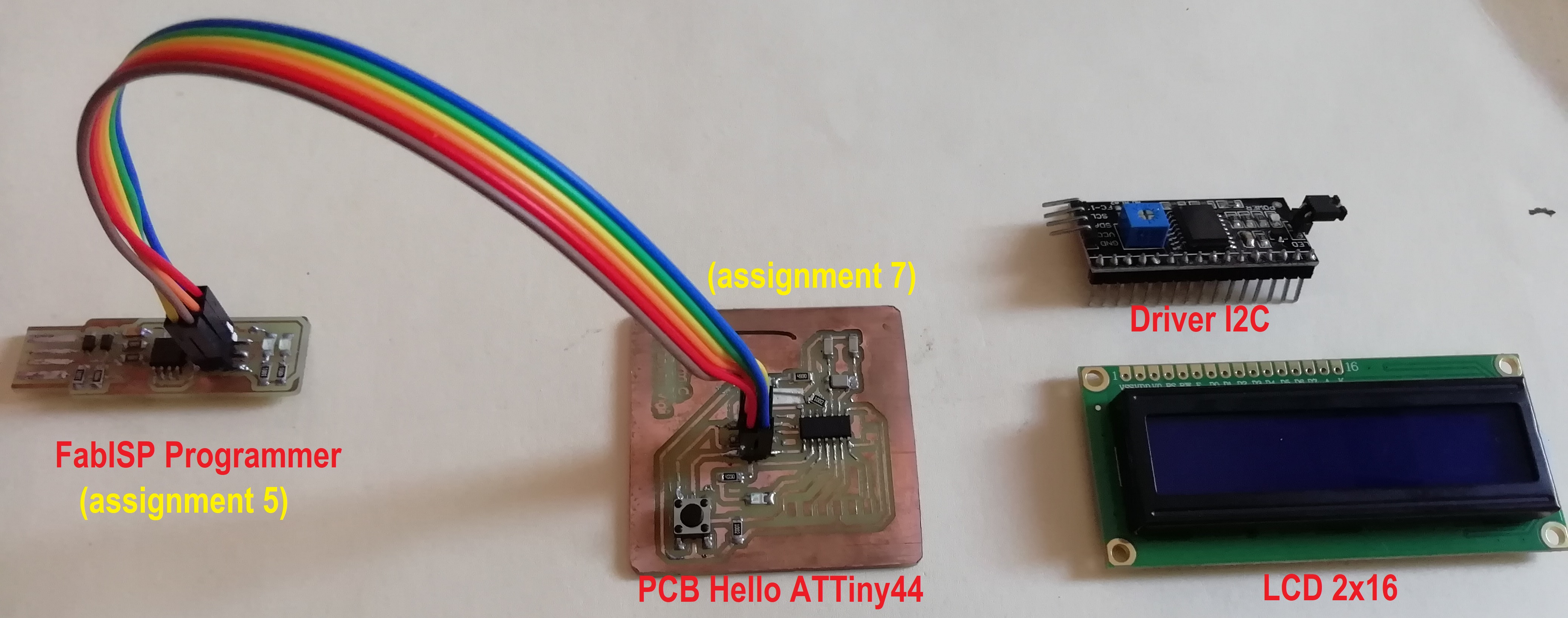
- Soldering pins to I2C driver:
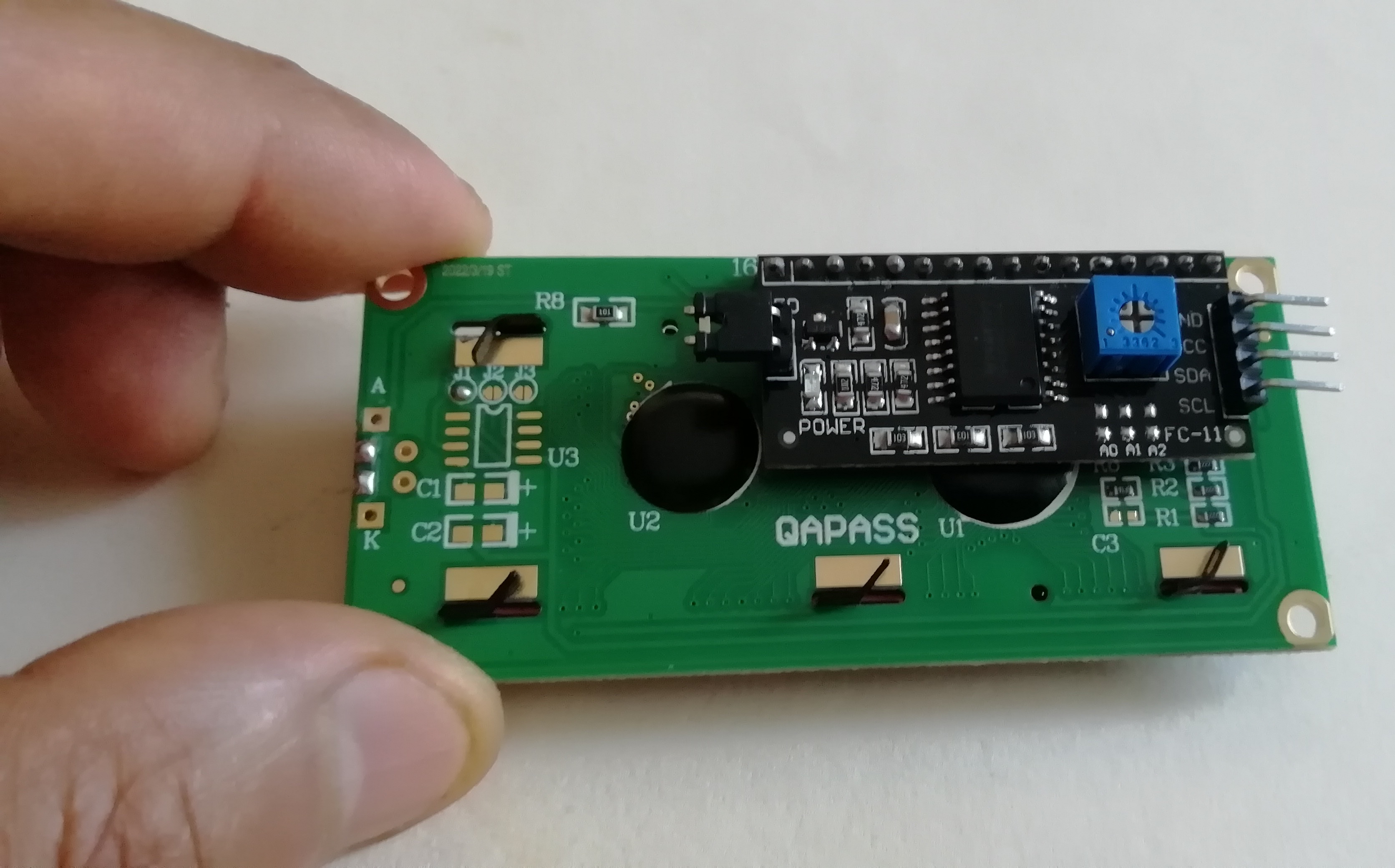
- I solder with solder and flux the I2C module and the LCD.
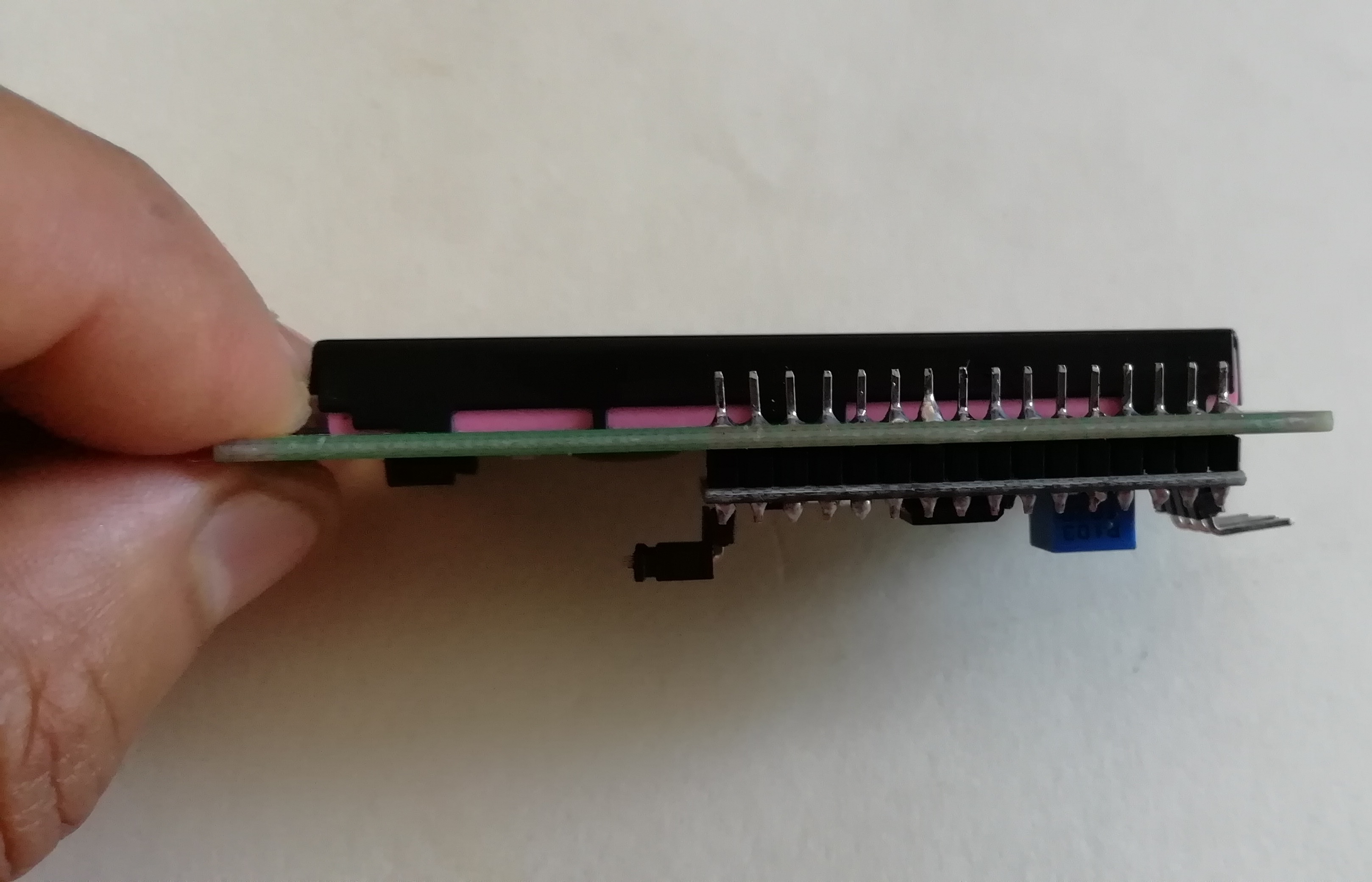
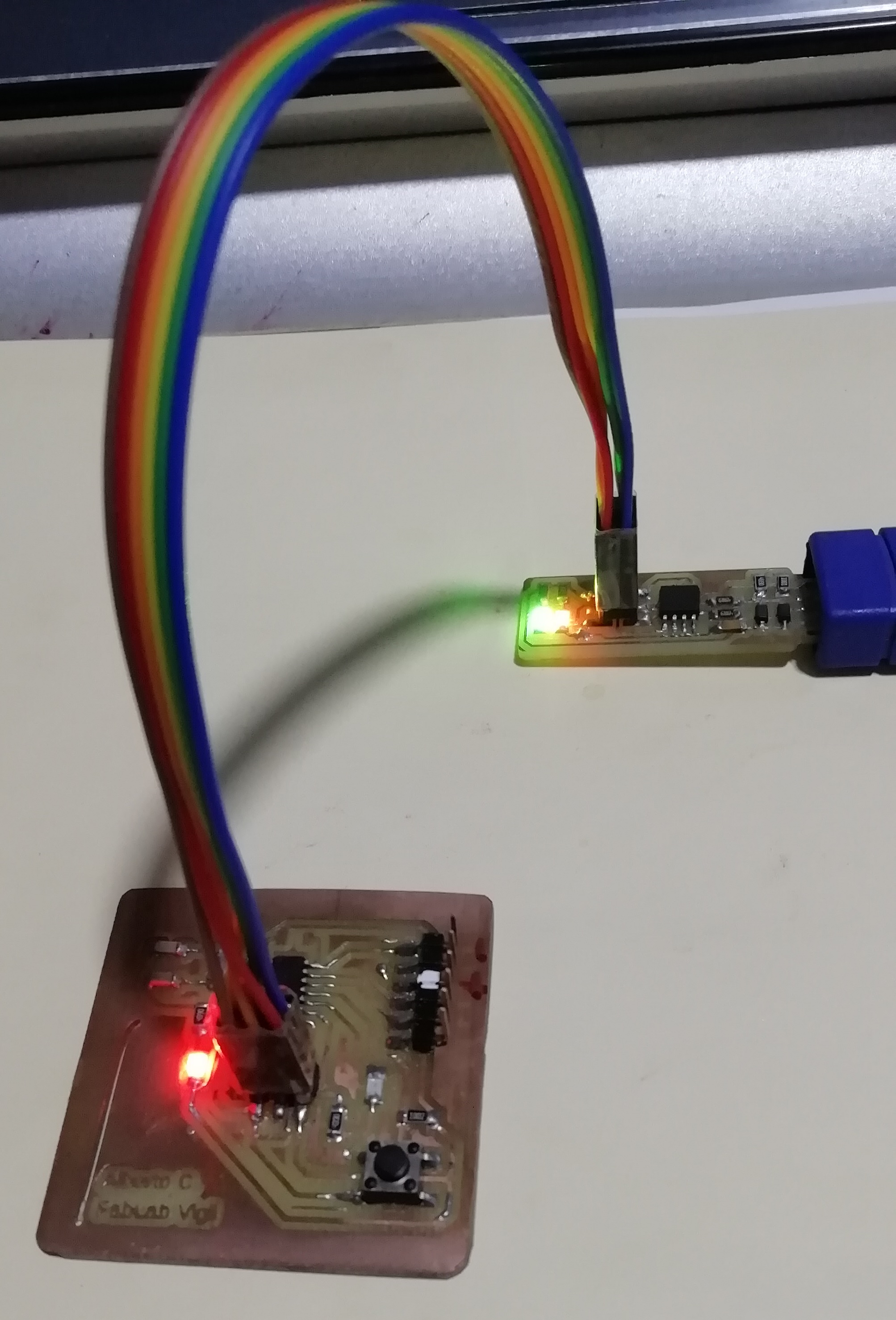
- After soldering the elements this is how I am left. I just need to program it, if everything is ok I will see a message on the LCD.
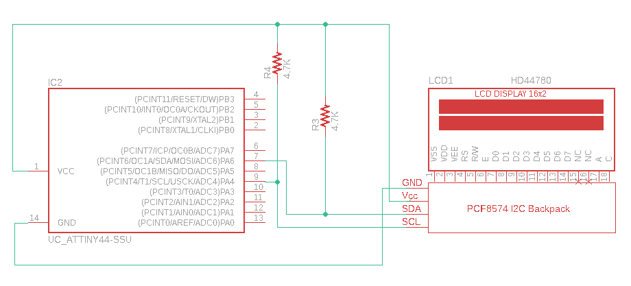
- The I2C communication is via two SDA and SCL cables from the I2C Adapter Module to the ATTiny44. The following diagram shows how I did it:
Programming:
-
I don’t want to go too deep into I2C, but there is an assignment later (14. Networking and communications) where I will go into more detail. The I2C device to communicate must have a specific address, in the case of the default I2C adapter it can be: 0x27, 0x3F or 0x20.
-
It is very important to correctly identify the I2C address of our module, otherwise the program will not work correctly.
-
In my case the LCD responded with the address 0x3F.
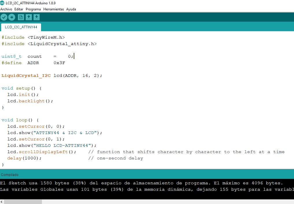
- The PCB with ATTiny44 that I designed I have to program it and make it show a text message on the LCD screen. For this I used the TinyWireM.h and LiquidCrystal_attiny.h libraries.
/*
ATtiny44/84 I2C pins:
ATtiny Pin 5 = SDA --> PB0
ATtiny Pin 7 = SCK --> PB2
*/
#include <TinyWireM.h>
#include <LiquidCrystal_attiny.h>
uint8_t count = 0;
#define ADDR 0x3F
LiquidCrystal_I2C lcd(ADDR, 16, 2);
void setup() {
lcd.init();
lcd.backlight();
}
void loop() {
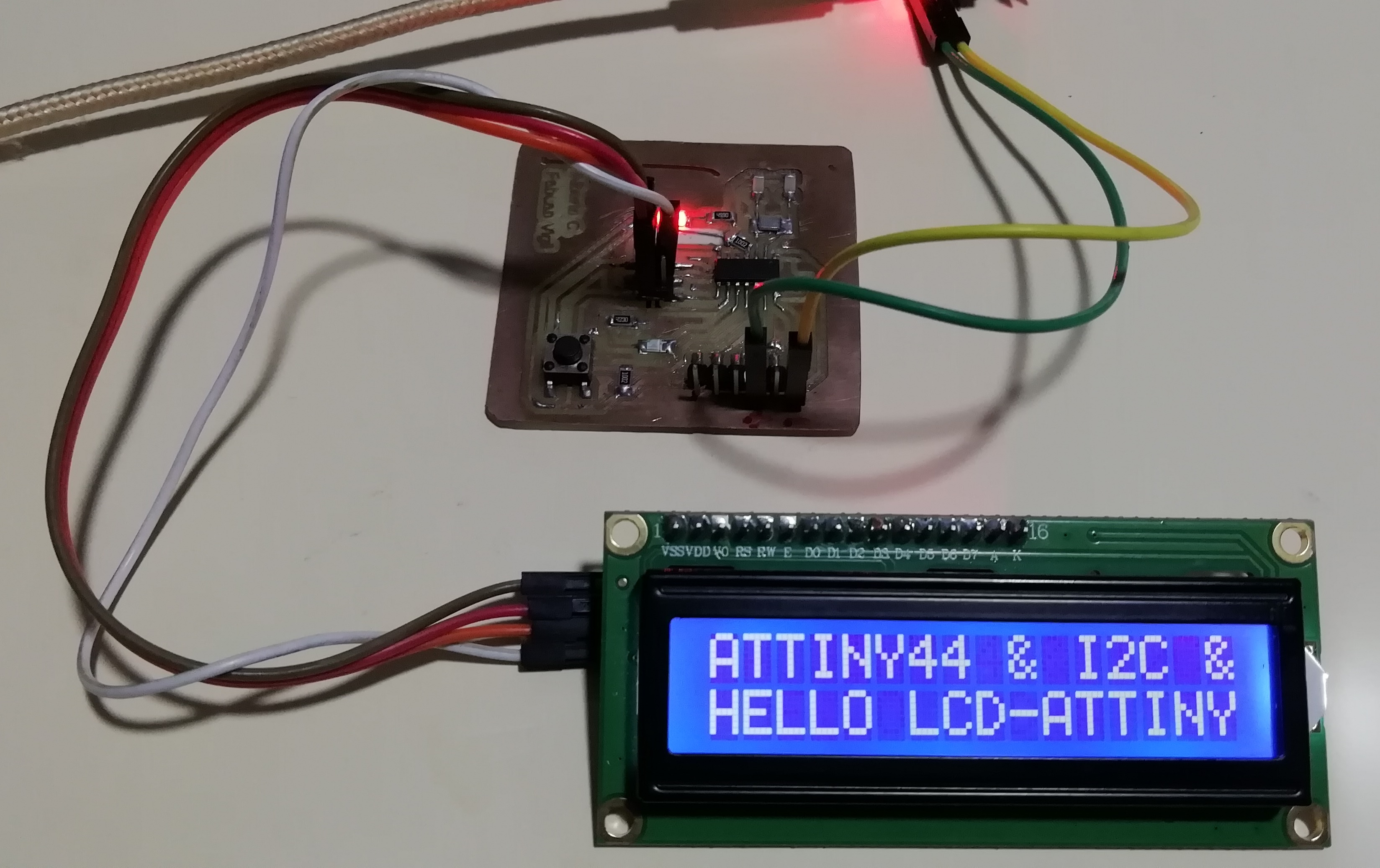
lcd.setCursor(0, 0);
lcd.show("ATTINY44 & I2C & LCD");
lcd.setCursor(0, 1);
lcd.show("HELLO LCD-ATTINY44");
lcd.scrollDisplayLeft(); // function that shifts character by character to the left at a time
delay(1000); // one-second delay
}
- I compile it, get no error and upload it to ATTiny44.
- First, I transfer the program from the FabISP Programmer to the ATTiny44 board, then I remove the programmer.
- Second, I connect the ATTiny44 board from the ISP jumper to the LCD to I2C Adapter Module.
- I power the ATTiny44 board and I should see the LCD with messages.
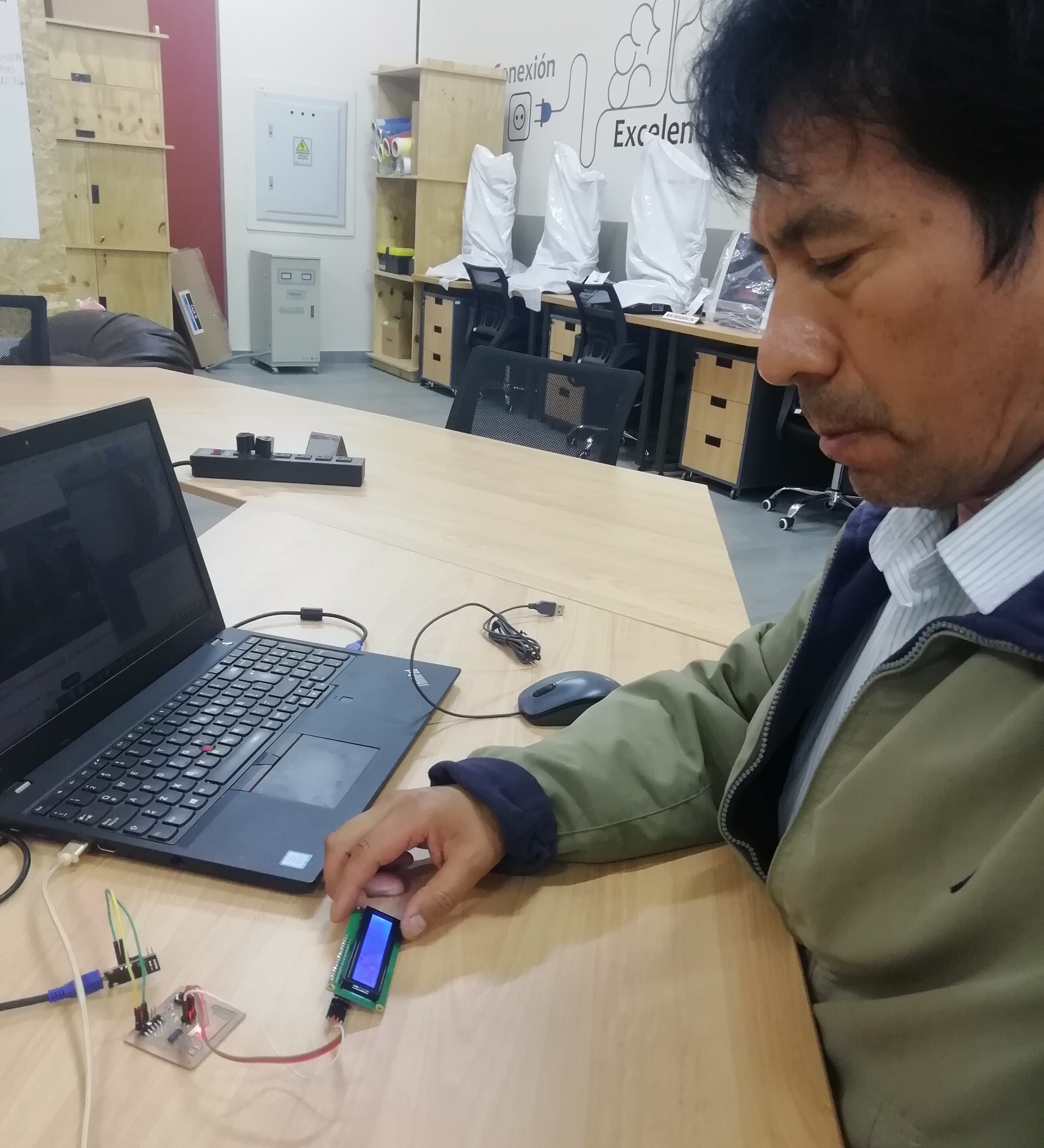
- Here I show a video of the whole process:
Programming languages and programming environments
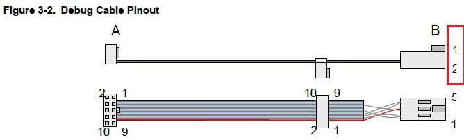
- At FabLab Vigil we have the Atmel-ICE programmer that records the AVR and SAM microcontroller families. I decided to use this recorder to program the ATTiny 44 and the ATMega 328P.
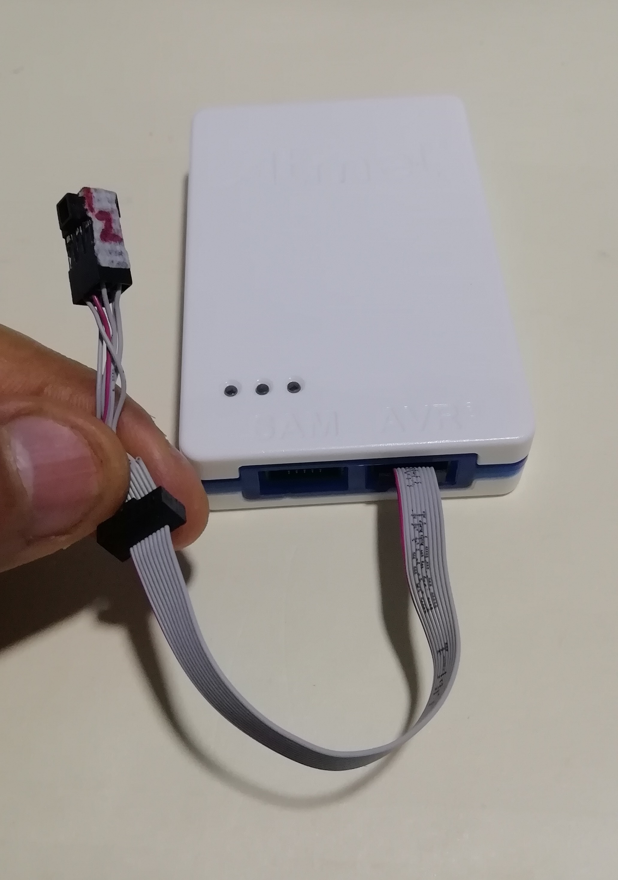
- The pins of the ISP connector according to the manual are:
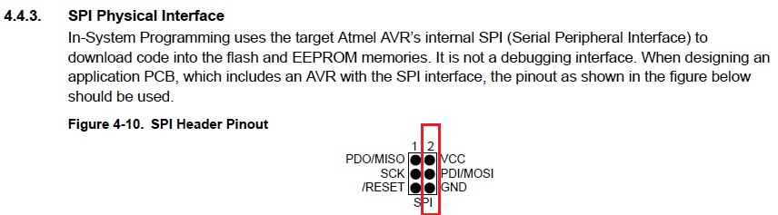
- The connection to the Board Hello ATTiny44 was made according to the figure. The ATTiny44 is ready to be programmed in C++ with the Atmel-ICE programmer.
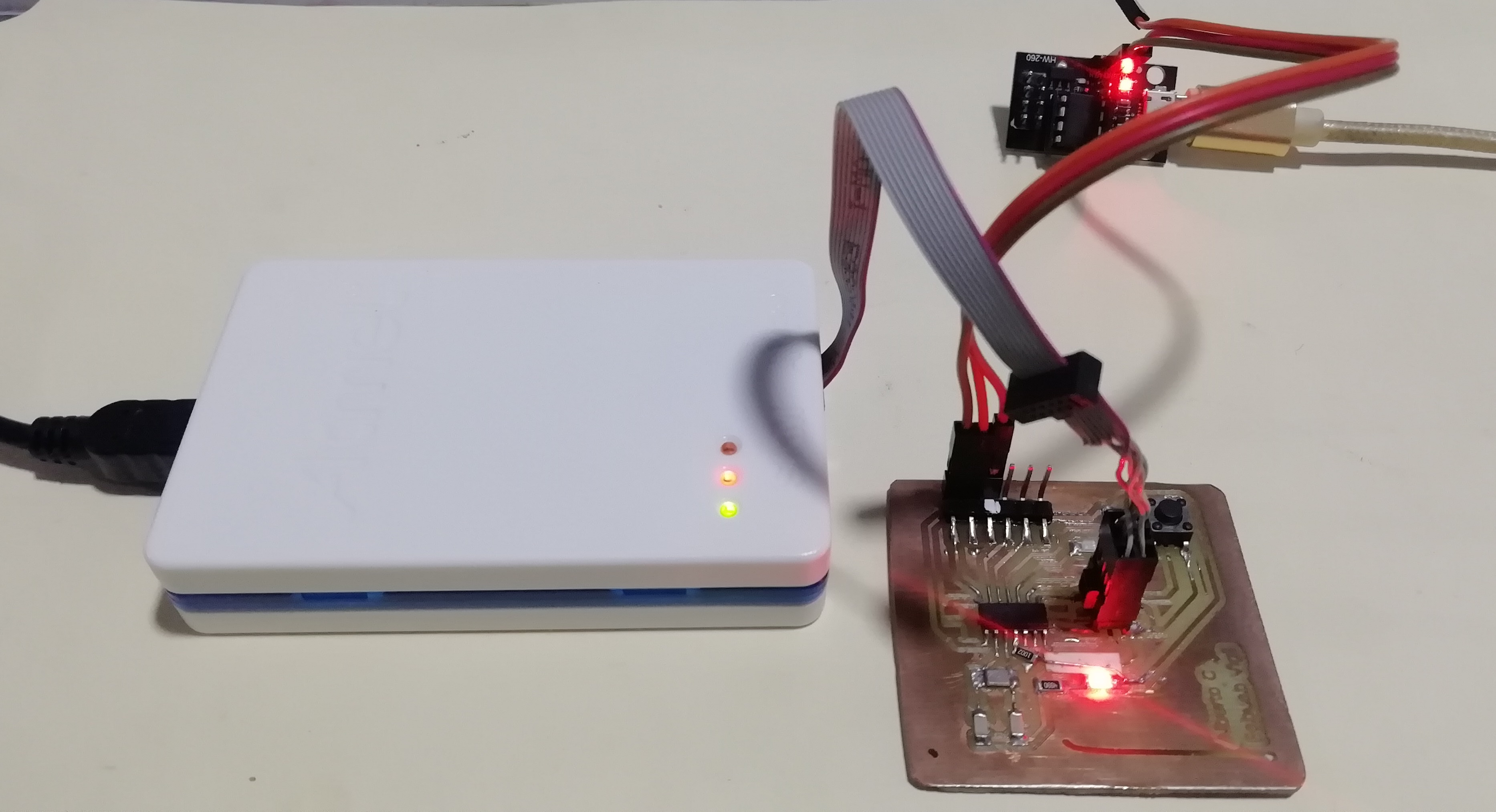
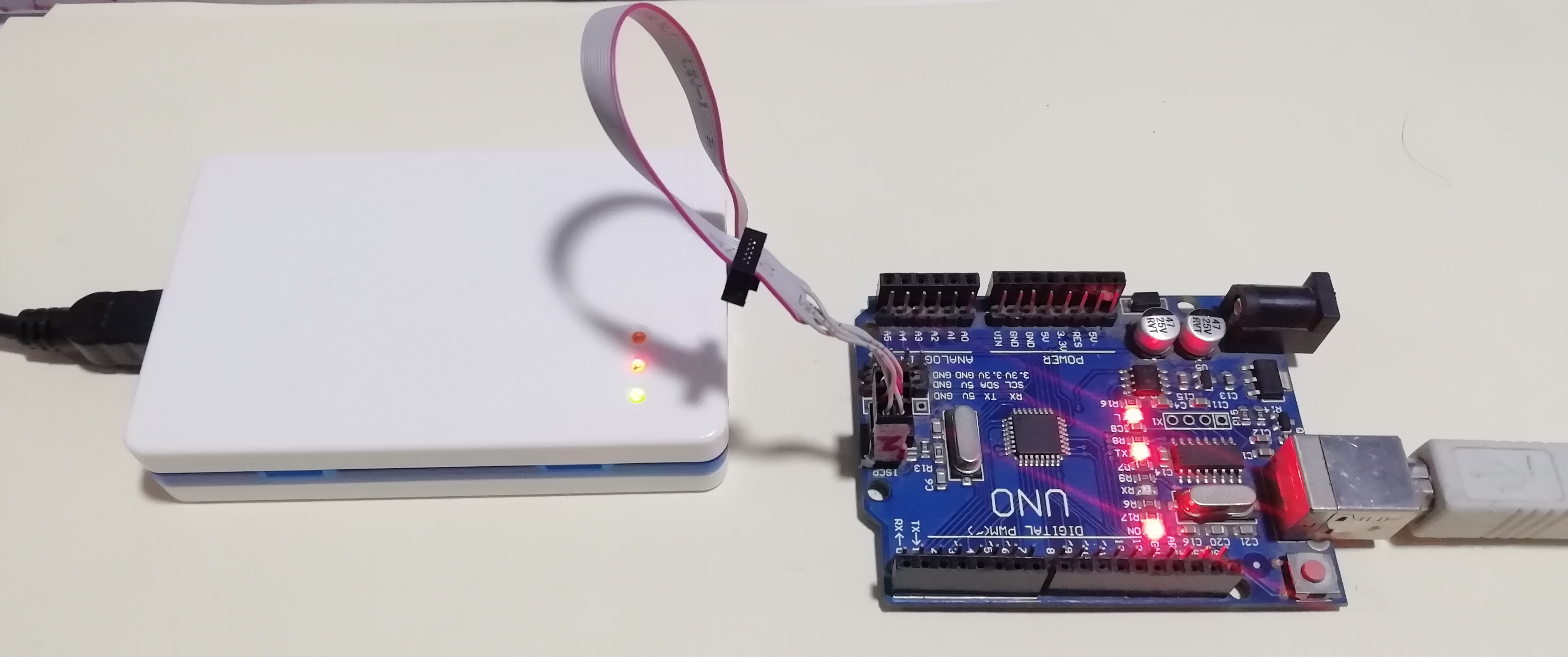
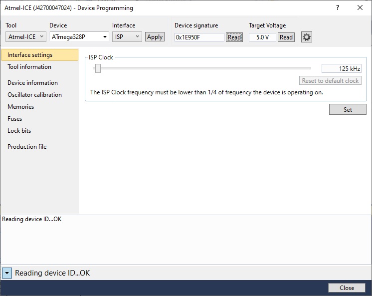
- Then I make the connection to the ATMega 328P board.
1. Programming in C++ in Atmel Studio the ATMega328P
- Microchip Studio 7.0 software download the installer and install:
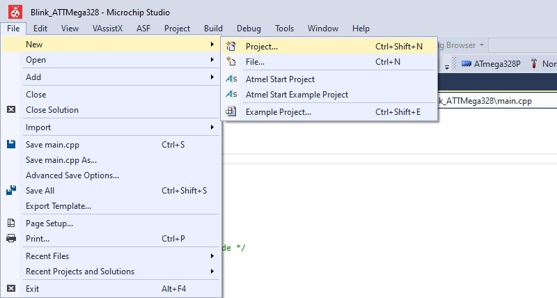
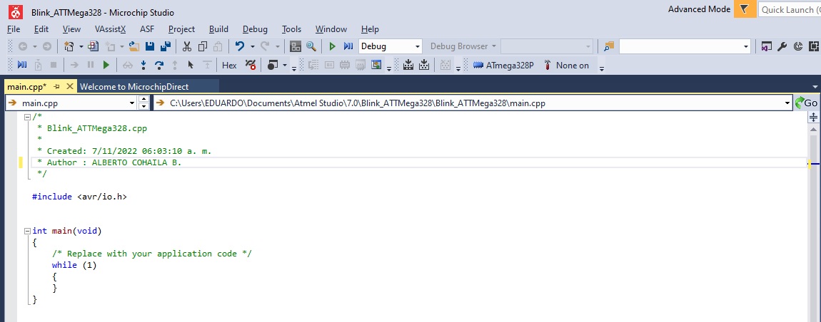
- Then I create a new project in File>>>New>>>Project
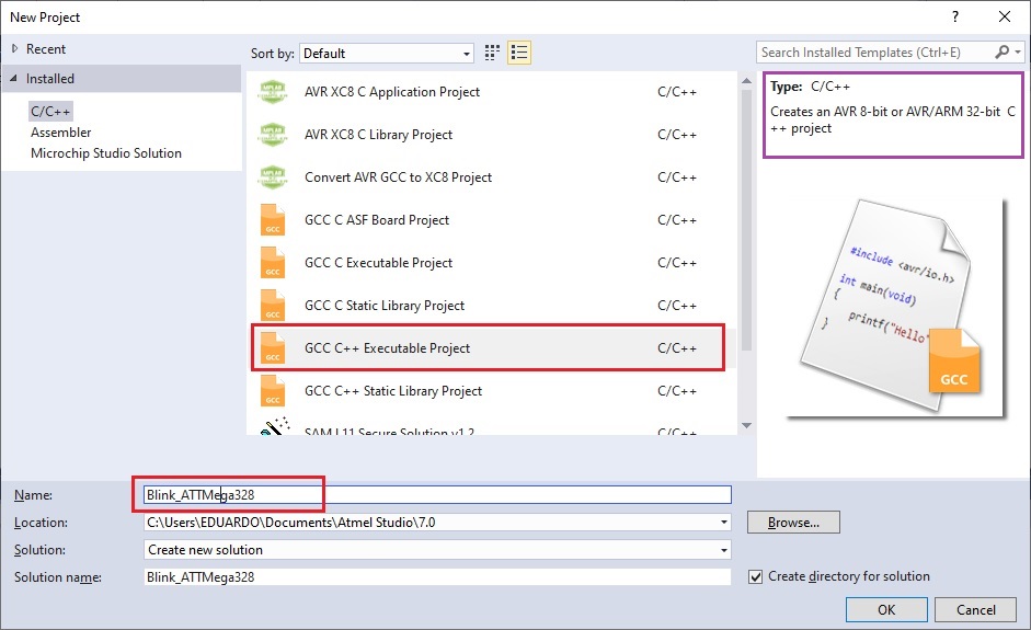
- I select the 8 bit AVR to program it in C++ code:
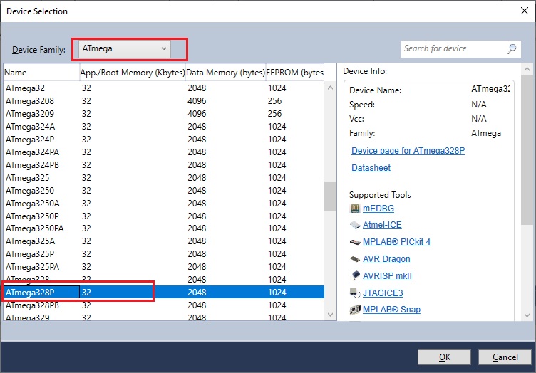
- The microcontroller of the Arduino is the ATMega328P, then OK. You are now ready to program the AVR.
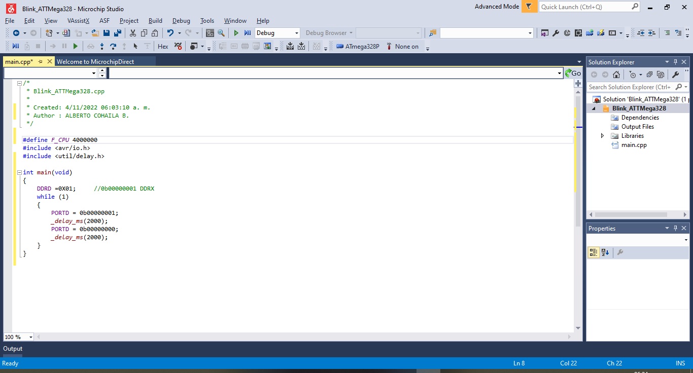
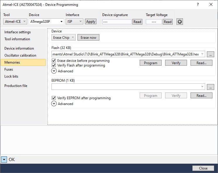
- To do the comparisons, I am going to program the LED blinking on the ATMega328P with Atmel-ICE.
- This is the code I used: The LED on pin 13 of the arduino turns on and off every 2 sec.
- Then I build it and see that it does not give errors:
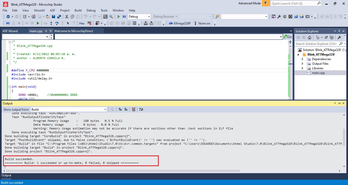
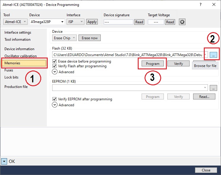
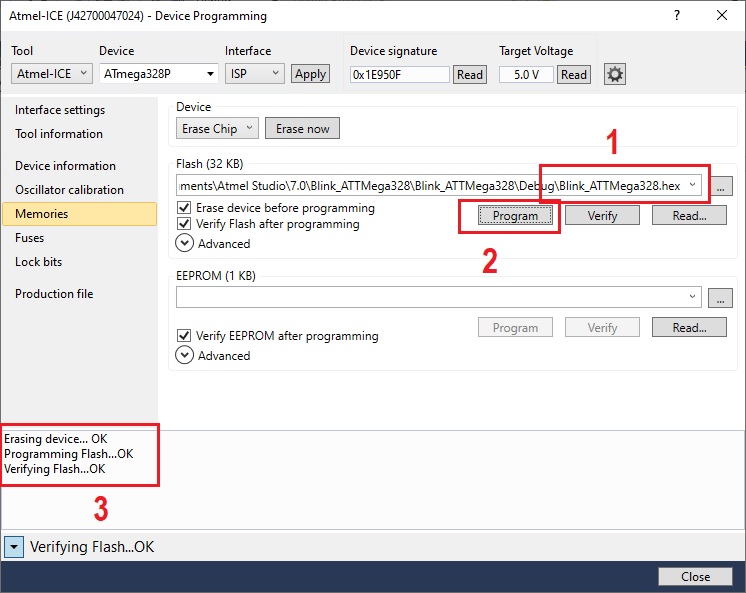
- Watch here a short video of the ATMega328P etching process with Atmel-ICE. Blink LED
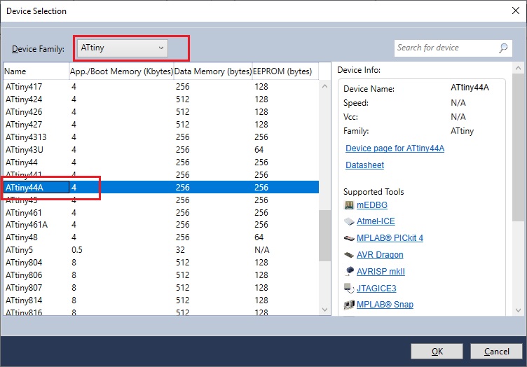
2. Programming in C++ in Atmel Studio the ATTiny44A
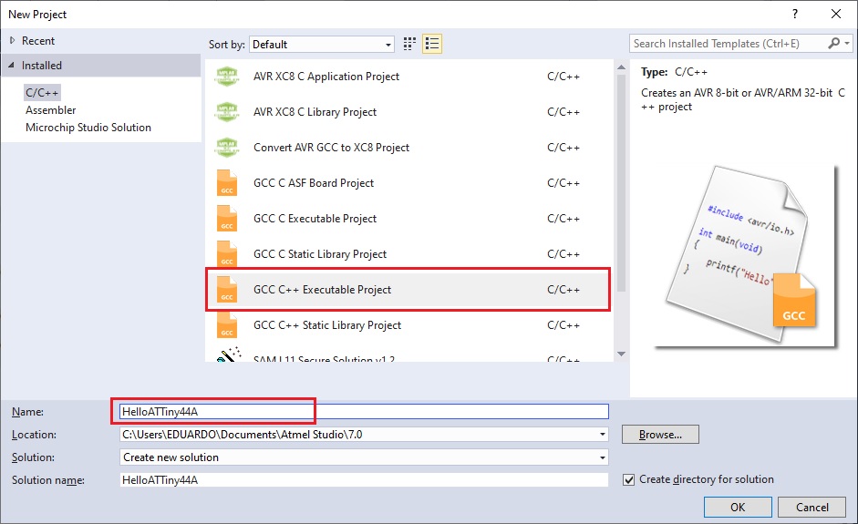
- I select the device to program ATTiny44A
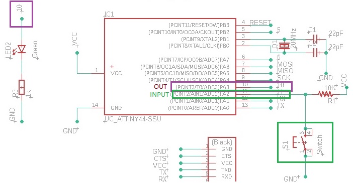
- According to my schematic (PCB), the PA3 pin is output (LED) and the PA2 pin is input (push button).
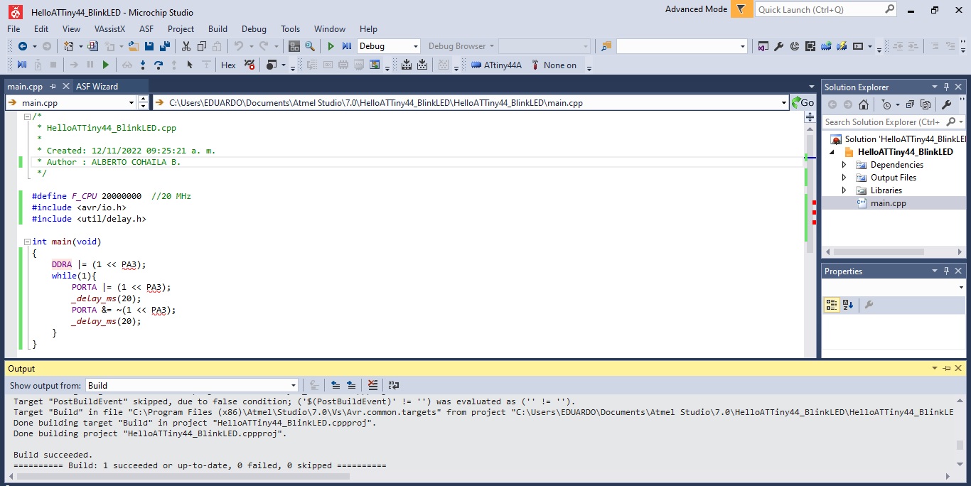
- Program the LED blinking, this is the code in C++:
/*
 * HelloATTiny44_BlinkLED.cpp
 *
 * Created: 12/11/2022 09:25:21 a. m.
 * Author : ALBERTO COHAILA B.
 */

#define F_CPU 20000000  //20 MHz
#include <avr/io.h>
#include <util/delay.h>

int main(void)
{
  DDRA |= (1 << PA3);
  while(1){
    PORTA |= (1 << PA3);
    _delay_ms(20);
    PORTA &= ~(1 << PA3);
    _delay_ms(20);
  }
}
- In the Microchip Studio IDE, i make the LED flashing program.
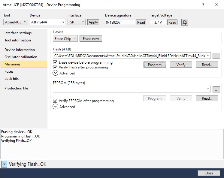
- Transfer the .hex file to the memory of the ATTIny44A
- LED blinking with ATTiny44A programmed in C++ with the Atmel-ICE programmer.
3. Switch LED state with push Button:
- The LED switch it values when the pushbutton is pressed. C++ code
/*
 * HelloATTiny44_PushButton_BlinkLED.cpp
 *
 * Created: 12/11/2022 04:09:23 p. m.
 * Author : ALBERTO COHAILA B.
 */

#define F_CPU 20000000  //20 MHz
#include <avr/io.h>
#include <util/delay.h>

int main(void)
{
        DDRA |= (1 << DDA3);  // Define pin A3 LED as an output
      DDRA &= ~(1 << DDA2);   // Define pin A2 Button as an input

      while (1) {
       uint8_t val = PINA & (1 << PA2);   //Push Button

       if(!val)
       {
         PORTA = PORTA | (1 << PA3);    //LED ON
       }
       else
       {
         PORTA = PORTA & ~(1 << PA3);   //LED OFF
       }
      }
}
- Using the ATMEGA-ICE programmer, I program the ATTiny44A in C++ to turn on the LED with an external pushbutton. What I conclude? that the C++ language is reduced and occupies less space in memory.
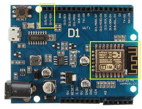
4. Node MCU - ESP32 and ESP8266:
- The ESP8266MOD integrates antenna switches, RF balun, power amplifier, low noise receive amplifier, filters and power management modules. The compact design minimizes the PCB size and requires minimal external circuitries.
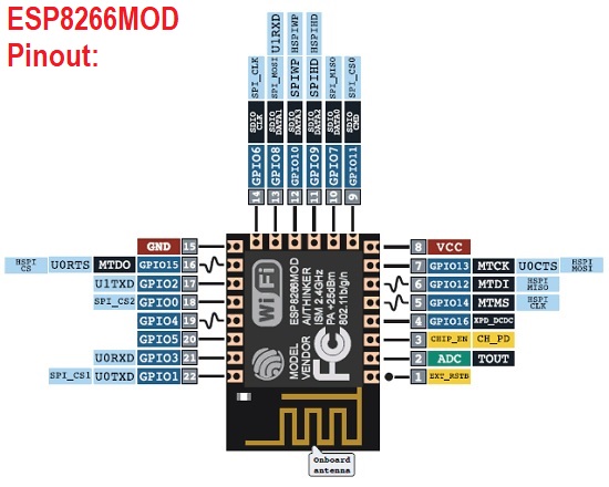
- These are the most important features summarized from the manufacturer’s data sheet:
- WiFi 2.4 GHz, support WPA/WPA2
- 32-bit architecture
- Integrated TCP/IP protocol stack
- Support Smart Link Function for both Android and iOS devices
- Dual and single antenna Bluetooth co-existence support with optional simultaneous receive (WiFi/Bluetooth) capability
- Support STA/AP/STA+AP operation modes
- Support I2C comunication mode
- Support SPI comunication mode
- It has 22 pins for operation and requires 3.3 Vdc power supply.
Installing ESP32 and 8266 Library in Arduino IDE:
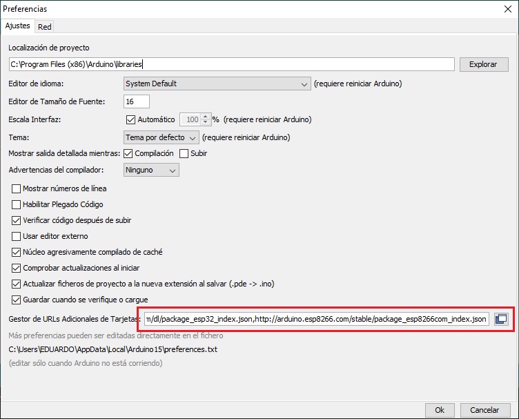
- First, in your Arduino IDE, go to: File >> Preferences
- Enter into the “Additional Board Manager URLs” field as shown in the figure below.
 https://dl.espressif.com/dl/package_esp32_index.json,
 http://arduino.esp8266.com/stable/package_esp8266com_index.json
-
Then, click the “OK” button:
-
Open the Boards Manager. Go to Tools > Board > Boards Manager
-
Search for ESP32 and press install button for the “ESP32 by Espressif Systems“ and the ESP8266: ESP32 and ESP8266 Add-on in Arduino IDE Windows, Mac OS X, Linux Installed
-
That’s it. It should be installed after a few seconds.
-
I am going to test it by programming the Hello Word on a 2x16 LCD Display via I2C communication. This is the connection and the code in C++:
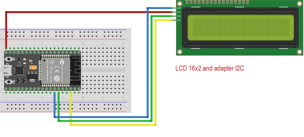
- I load the program to board ESP32 and it is ready to work.
 // ESP32 and ESP8266 with LCD interface I2C

#include <LiquidCrystal_I2C.h>
LiquidCrystal_I2C lcd(0x3F, 16, 2);

void setup() {
  lcd.init();
  lcd.backlight(); //Turn on the backlight
}

void loop() {
  lcd.clear();
  lcd.setCursor (0, 0); //put the cursor on the coordinates (x,y)
  lcd.print(" Hello, World! ");
  delay(1000);
  lcd.clear();
  lcd.setCursor (0, 1);
  lcd.print(" Hello, World! ");
  delay(1000);
}
- Watch the video: ESP32
Arduino Wemos D1:
- This device has a 3.3 volt CMOS logic and processor (microcontroller) on the ESP8266 has a 32-bit architecture, which will make the handling of this board more similar to an Arduino DUE, UNO or Mega. In terms of programming it is very similar to the ESP32.
- This is the connection:
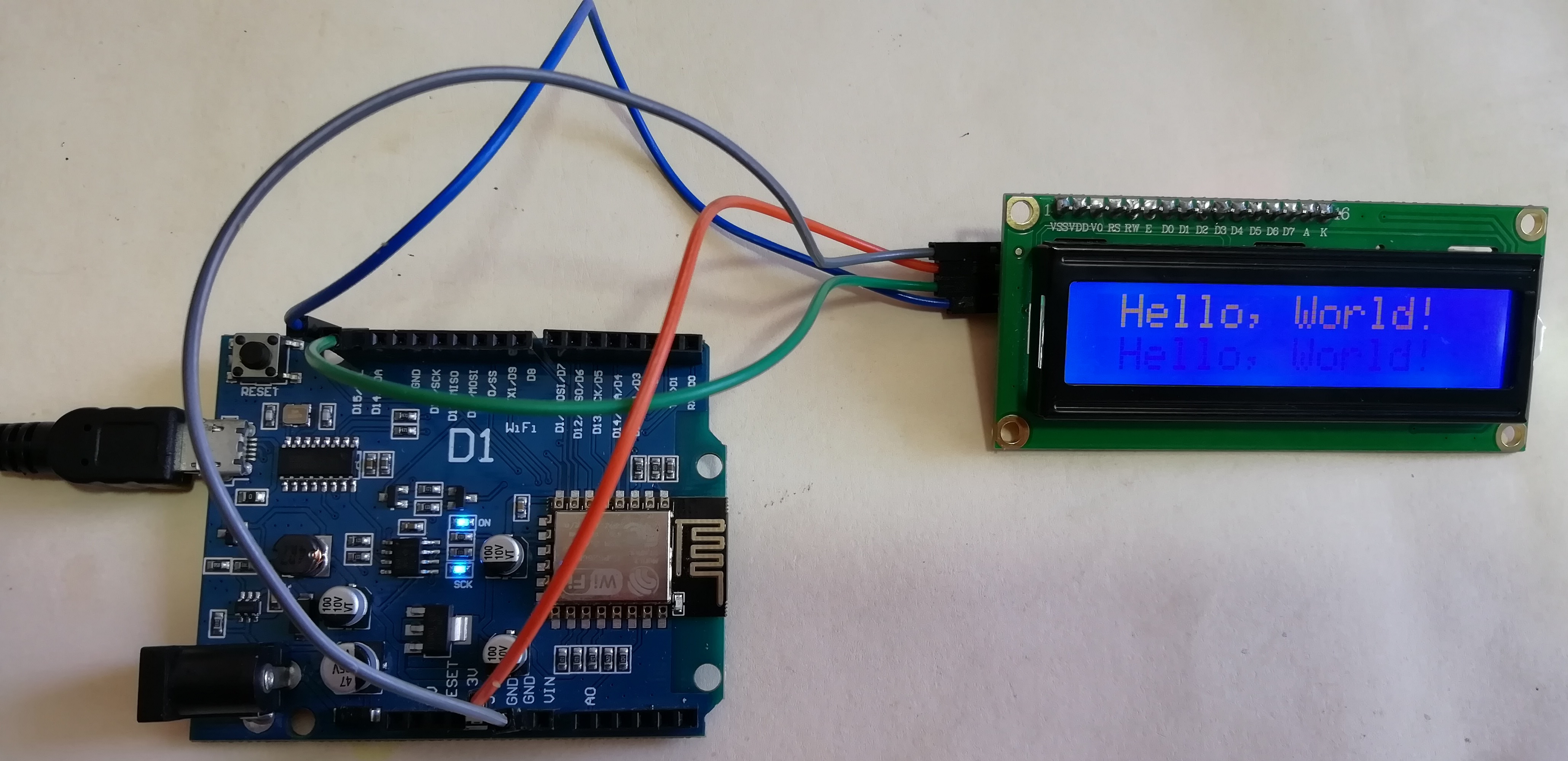
- Watch the video: ESP8266MOD
B. GROUP ASSIGMENT
-
To compare the performance and development workflows of the following architectures, for the blink program to compare the delay routines:
-
ESP8266
- ATMega328P
-
Attiny44A
-
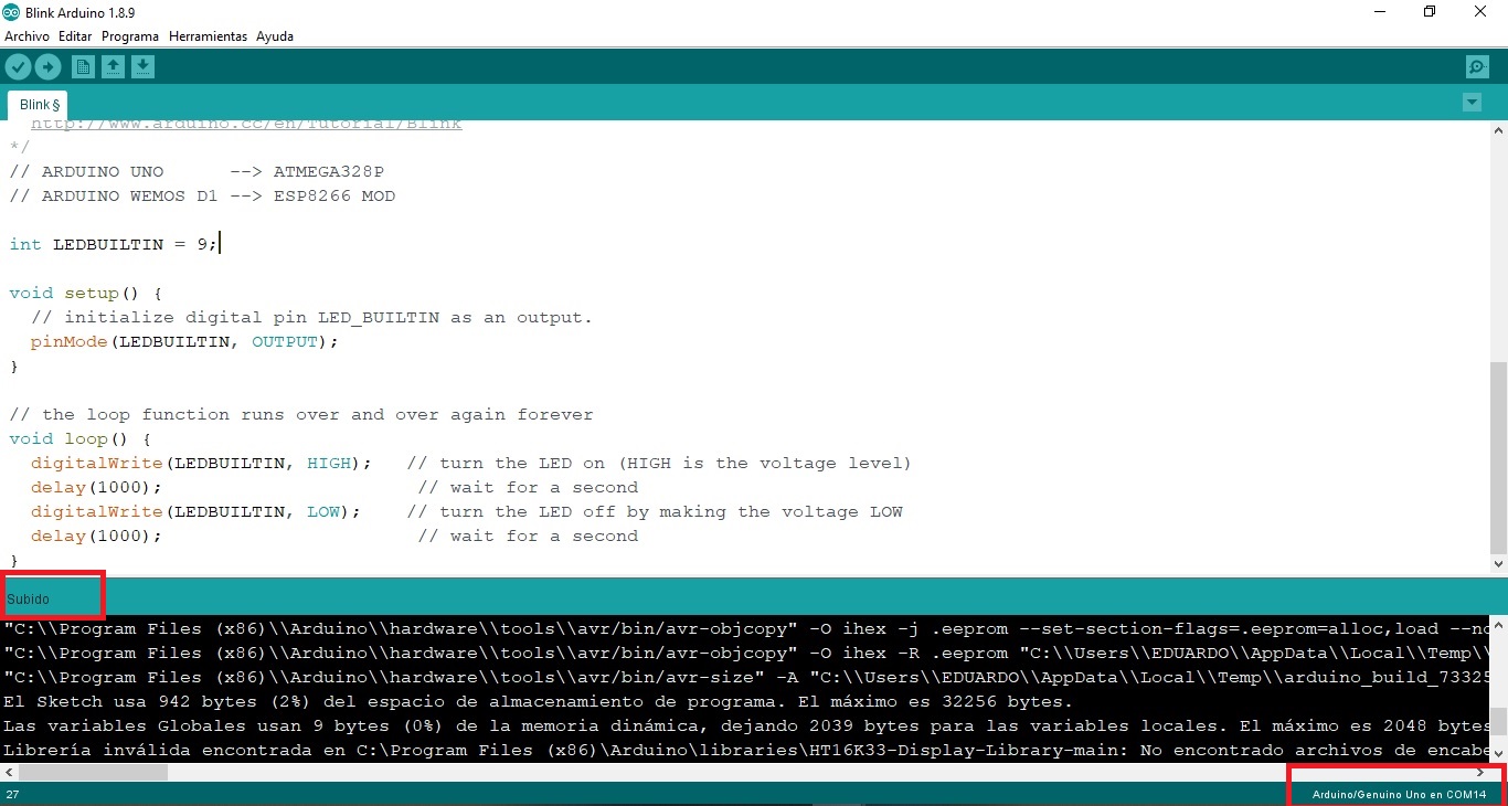
This is the C++ code I used for LED blinking of the 8-bit AVR microcontroller ESP8266 and ATMega328P:
/*This example code is in the public domain.
http://www.arduino.cc/en/Tutorial/Blink
*/
// BLINK LED:
// ARDUINO UNO --> ATMEGA328P
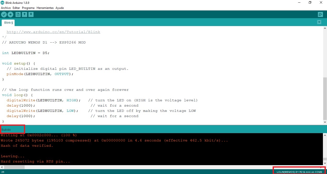
// ARDUINO WEMOS D1 --> ESP8266 MOD
int LEDBUILTIN = 9; //ATMEGA328P
//int LEDBUILTIN = D5; //ESP8266 MOD
void setup() {
// initialize digital pin LED_BUILTIN as an output.
pinMode(LEDBUILTIN, OUTPUT);
}
// the loop function runs over and over again forever
void loop() {
digitalWrite(LEDBUILTIN, HIGH); // turn the LED on (HIGH is the voltage level)
delay(1000); // wait for a second
digitalWrite(LEDBUILTIN, LOW); // turn the LED off by making the voltage LOW
delay(1000); // wait for a second
}
- Blink LED microcontrolador AVR, 8 bits, ATMega 328P. Loading the code into memory:
- Blink LED microcontrolador, 32 bits, ESP8266. Loading the code into memory:
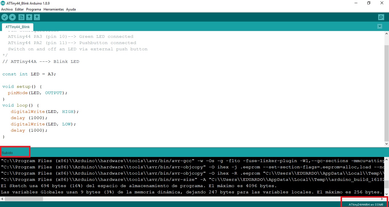
- Blink LED microcontrolador AVR, 8 bits, ATTINY44. Loading the code into memory:
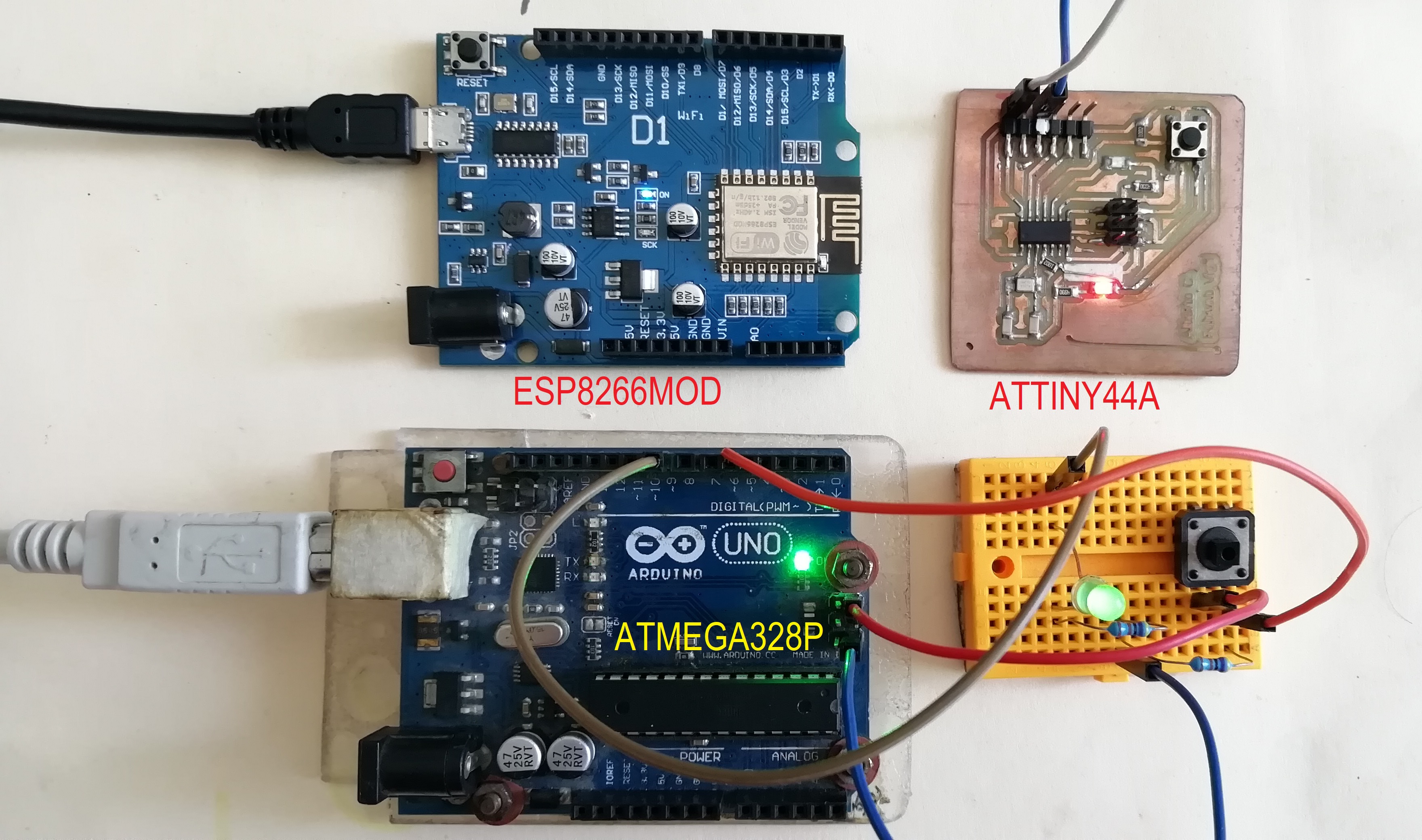
- The microcontroller triad
COMPARATIVES:
- In this video you can see the result of the LED flicker and LED comparisons of the three architectures:
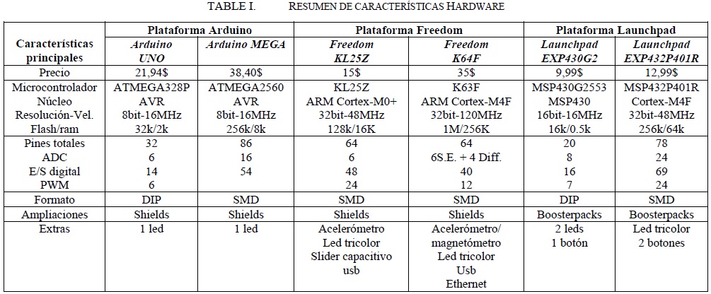
- I can conclude that all three architectures work fine in C++ with the Arduino IDE, the 1 sec change times are equal to sight. I had problems in addressing the ESP8266 pins. Another difference is that by offering WIFI the ESP its bit capacity increases to 32, unlike the AVRs analyzed are 8 bits. Another difference I found is that the AVRs are more flexible and work at 5V unlike the ESP which works at 3.3V.See the table different hardware platforms:
Design Files
| Description | Files | |
|---|---|---|
| Blink_ATTMega328 | Blink_ATTMega328.rar | |
| HelloATTiny44_BlinkLED | HelloATTiny44_BlinkLED.cpp | |
| HelloATTiny44_PushButton_BlinkLED | HelloATTiny44_PushButton_BlinkLED.cpp | |
| HelloATTiny44A | HelloATTiny44A.cpp | |
| LED | LED.cpp | |
| LCD_I2C_ATTINY44 | LCD_I2C_ATTINY44.ino | |
| LCD_I2C_Arduino | LCD_I2C_Arduino.ino |