Final project
Tank level control
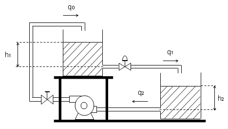
I developed a prototype tank level control for teaching and training in the area of automatic process control, without neglecting the high cost of commercial prototypes.
My inspiration
As a teacher of Higher Technical Education and University I am always looking for ways that students maintain motivation for learning in the subjects I teach, these subjects belong to the area of automatic control and automation, so to arouse greater interest in them I was inspired by commercial prototypes that we do not have because of the high cost of investment. The control theory addresses (to start) models of control of simple and cascade tanks, it was then that it occurred to me to develop this project I called it: Tank level control prototype.
Materials and component
| Quantity | Material | $ |
|---|---|---|
| 1 | 3mm MDF plate of 60 cm x 80 cm | 7.5 |
| 1 | PLA type filament for 3D printing | 5 |
| 1 | Vinyl of white color of 14 cm x 10 cm | 3 |
| 1 | A 5 l water tank | 2.5 |
| 2 | Meter of 1/4” flexible plastic hose | 0.5 |
| sub total 1 | 18.5 |
| Quantity | Component | $ |
|---|---|---|
| 1 | ATTiny44A | 5 |
| 2 | non-contact liquid level Sensors - XKC-Y25-NPN | 10 |
| 1 | One 12 V, 2A, 3.5 l/min water pump | 15 |
| 1 | One L298B power driver | 1.8 |
| 1 | 16x2” LCD screen | 2.5 |
| 1 | Variable power Supply from 1.2 V to 24 V @ 2A. | 11 |
| sub total 2 | 45.8 |
| Total | $ |
|---|---|
| 64.3 |
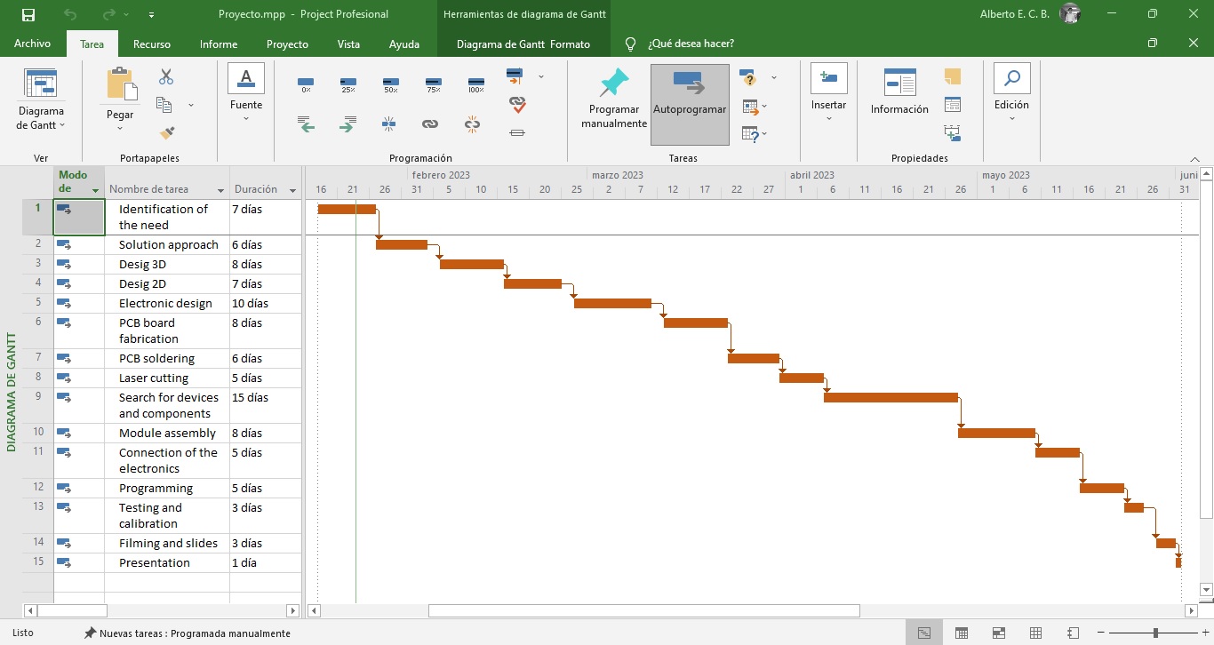
Project Execution Plan
For the execution of this project, the following activities plan was prepared with the required times:
Project development
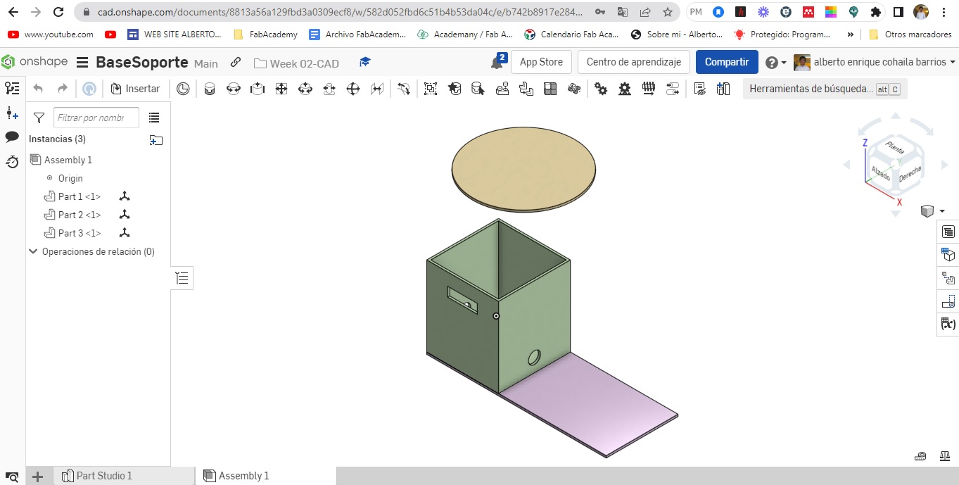
To begin with, we used Computer Aided Design (CAD) tools to make 2D and 3D designs. The program used was Onshape.
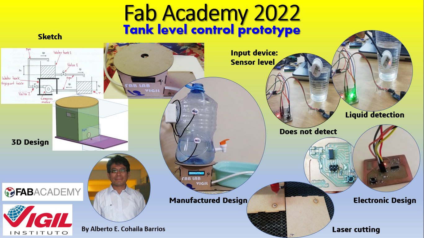
Next I will show some images of the designs made:

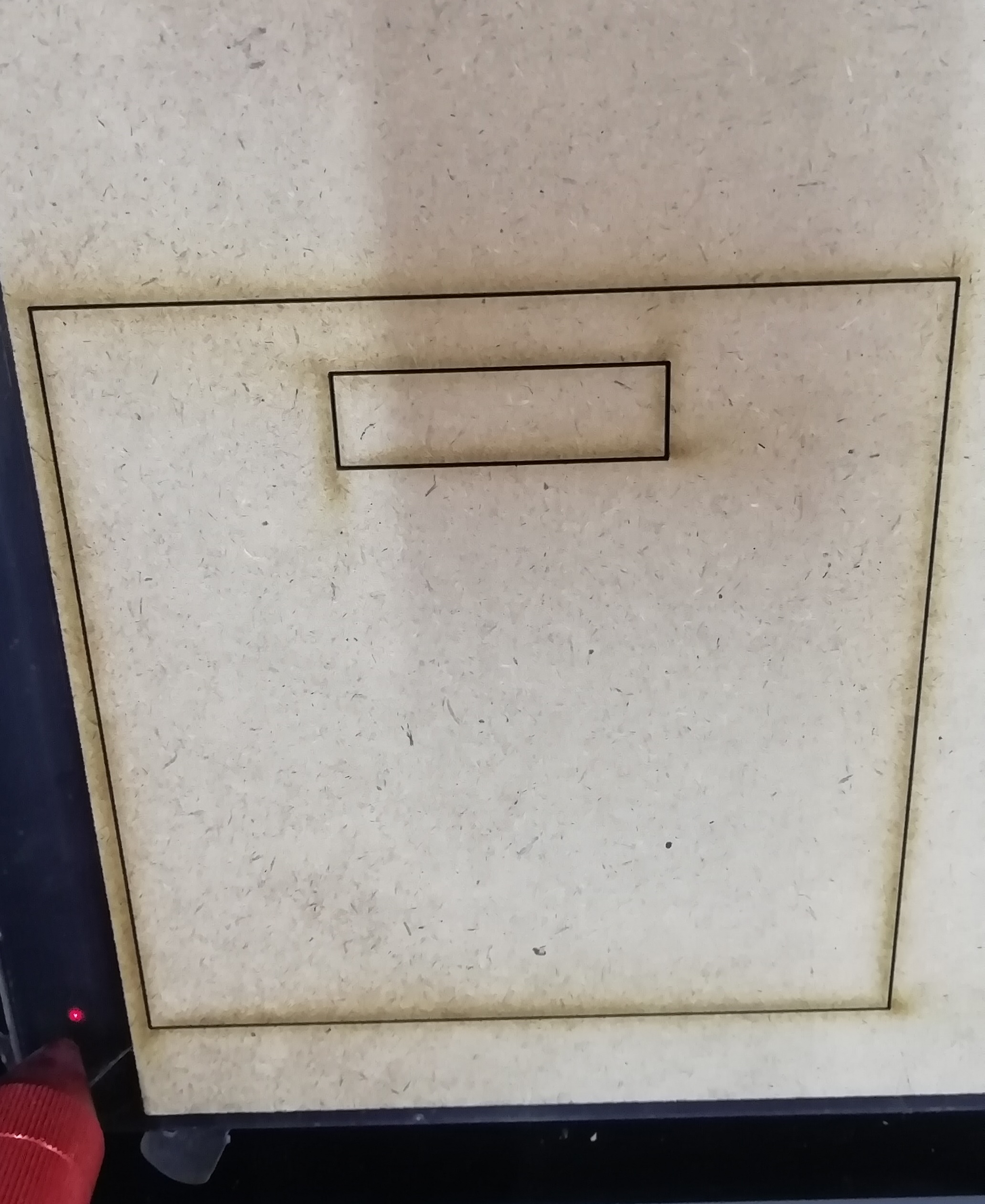
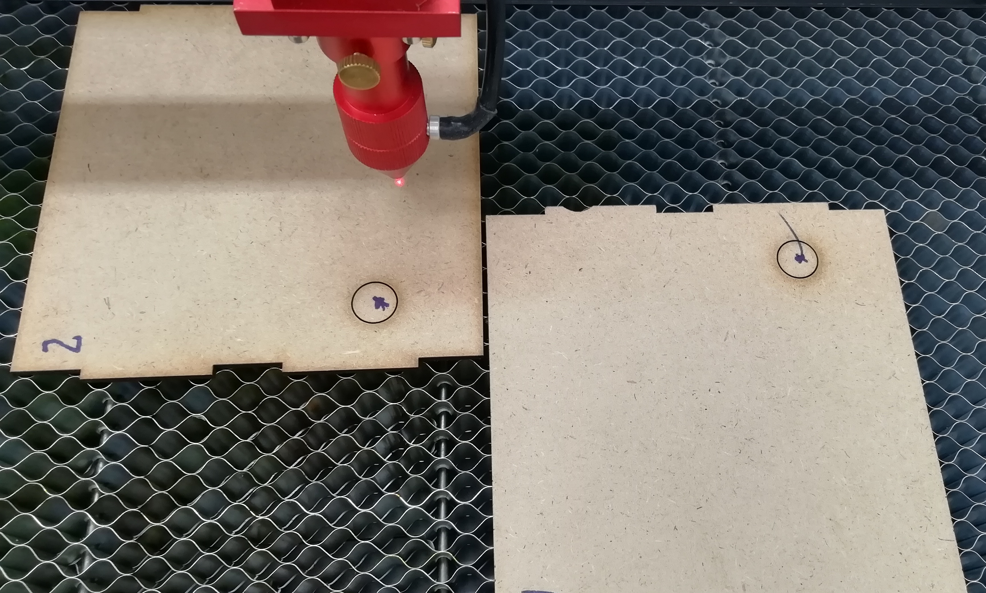
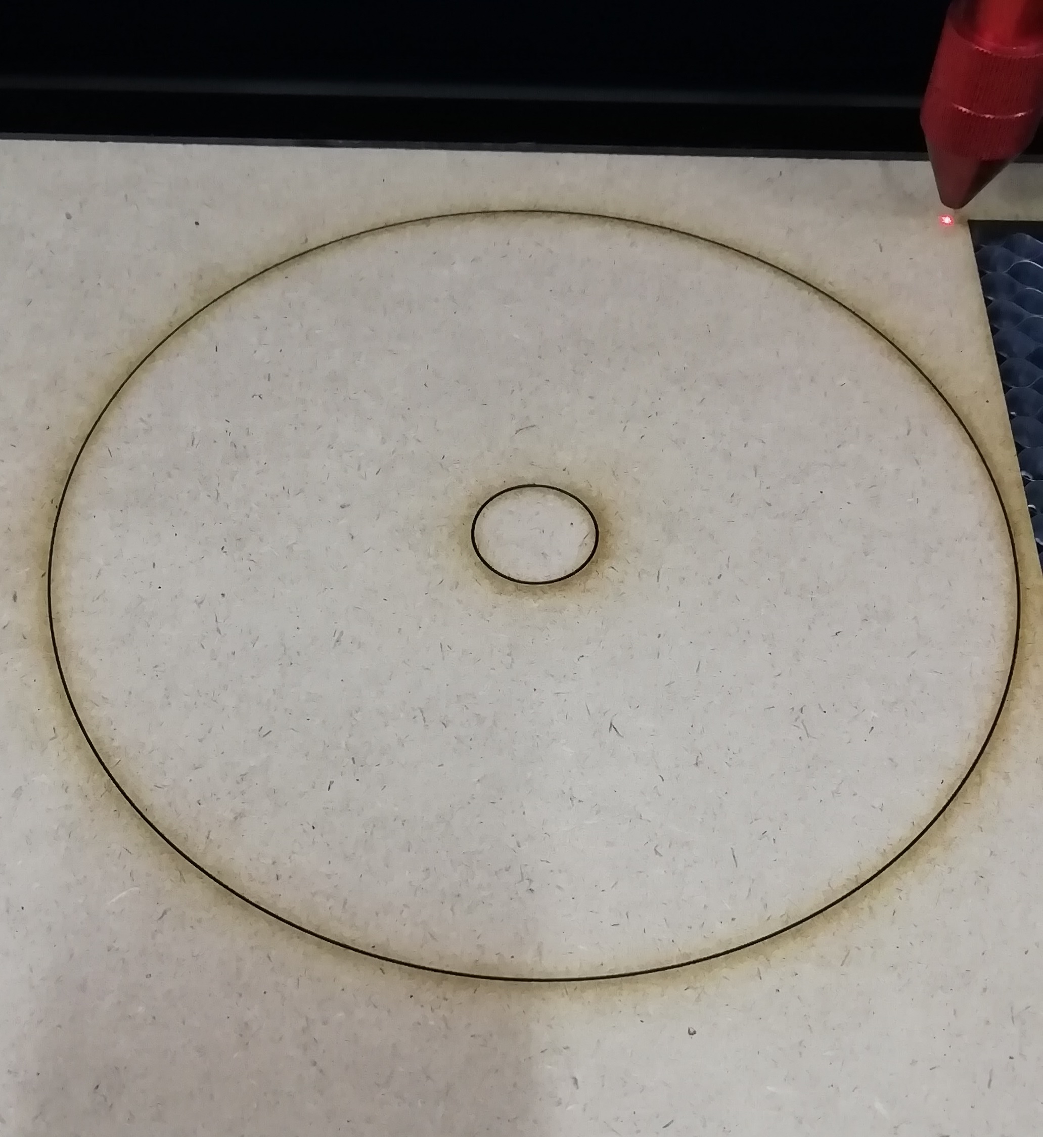
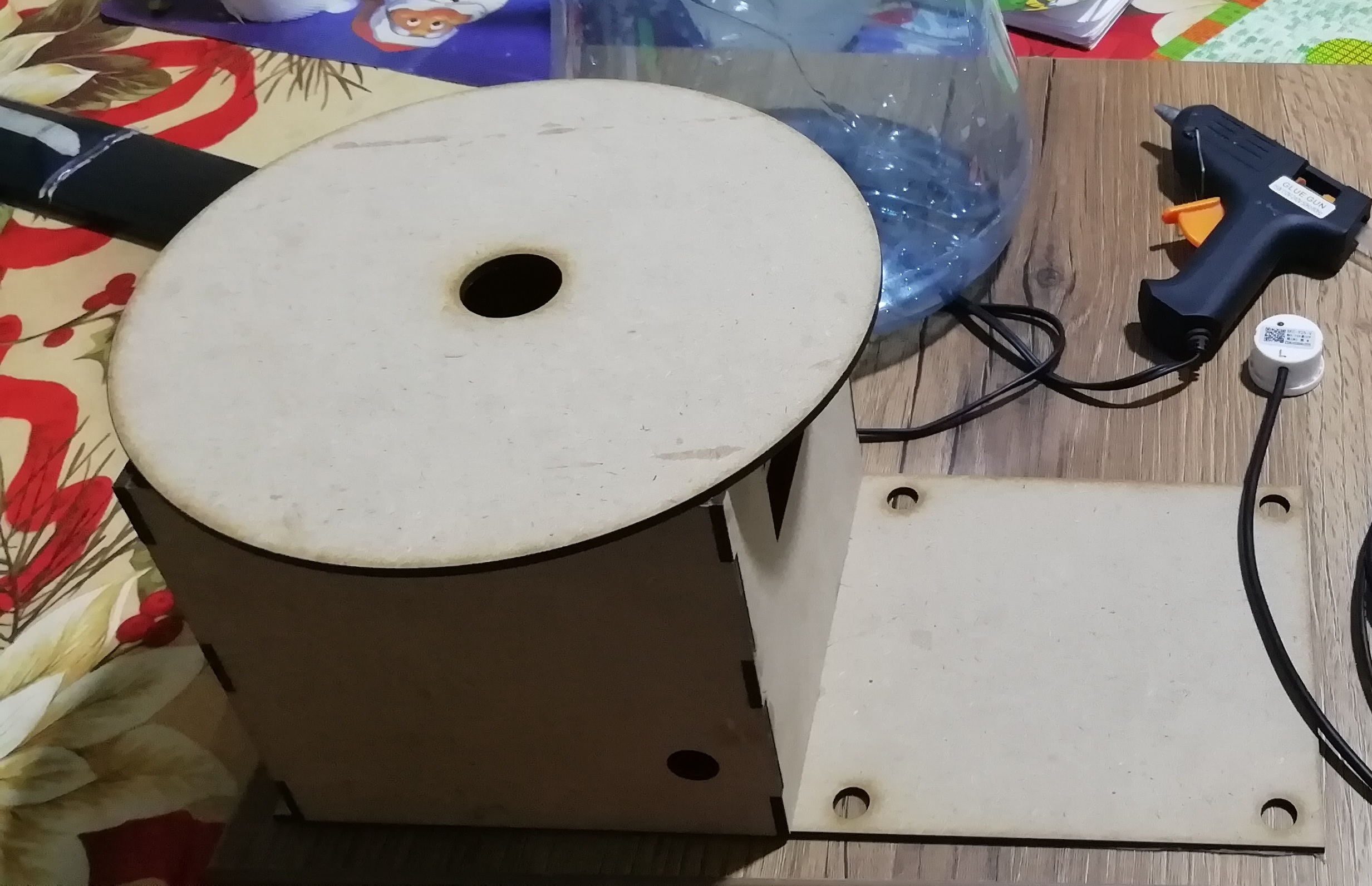
a) I used Computer Controlled Cutting
Using the laser cutter I fabricated the tank base and support, as well as the water pump compartment and circuitry. Here I show some of them:

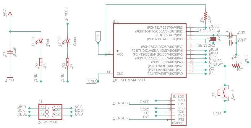
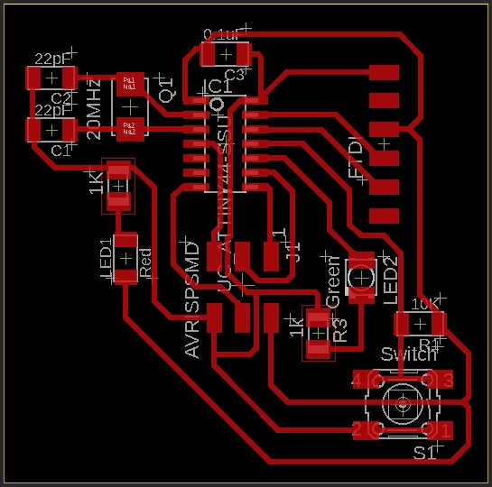
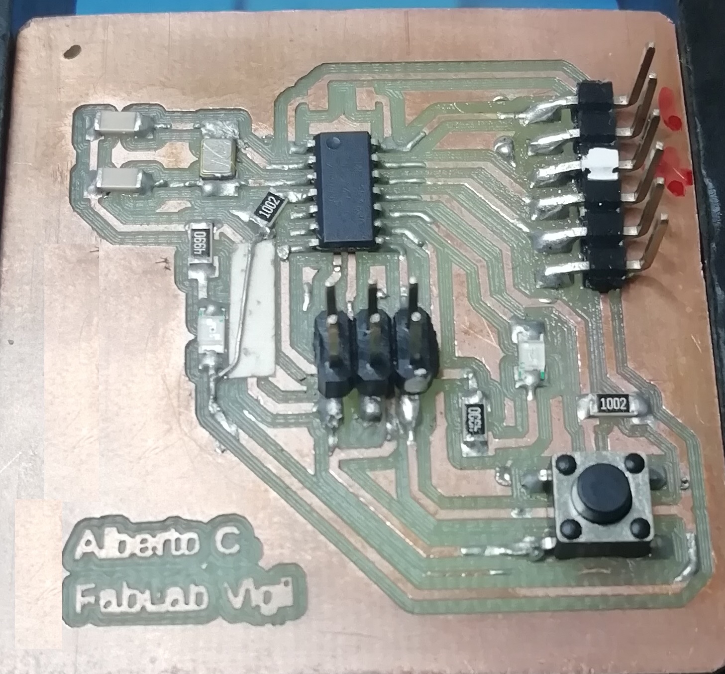
b) I used electronic design, electronic production and embedded programming.
For the electronic design I used Eagle Autodesk ver 9.6.2, the gerber files were generated and the boards were manufactured in the Monofab CNC, I also made control programs for the ATTiny44A microcontroller.
Here I show some images:
Electronic Design

Electronic Production

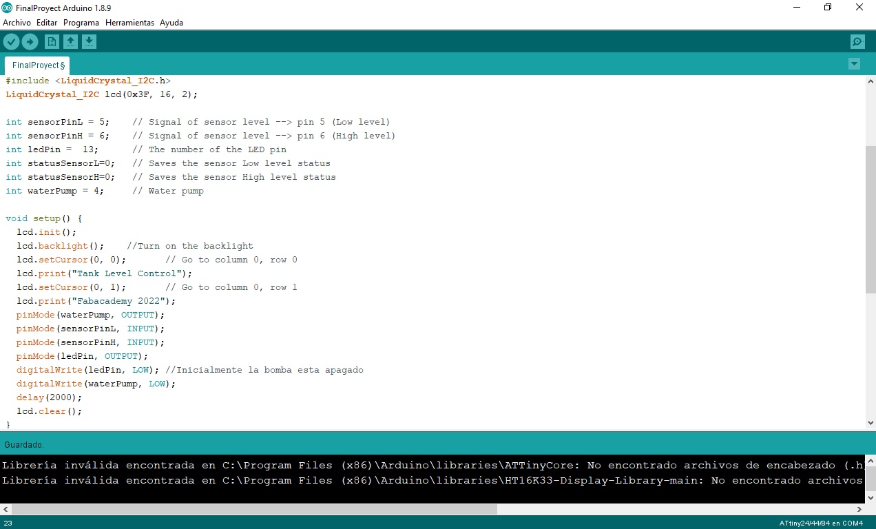
Embedded Programming
This is the coding for the microcontroller I used:
#include <LiquidCrystal_I2C.h>
LiquidCrystal_I2C lcd(0x3F, 16, 2);
int sensorPinL = 5; // Signal of sensor level --> pin 5 (Low level)
int sensorPinH = 6; // Signal of sensor level --> pin 6 (High level)
int ledPin = 13; // The number of the LED pin
int statusSensorL=0; // Saves the sensor Low level status
int statusSensorH=0; // Saves the sensor High level status
int waterPump = 4; // Water pump
void setup() {
lcd.init();
lcd.backlight(); //Turn on the backlight
lcd.setCursor(0, 0); // Go to column 0, row 0
lcd.print("Tank Level Control");
lcd.setCursor(0, 1); // Go to column 0, row 1
lcd.print("Fabacademy 2022");
pinMode(waterPump, OUTPUT);
pinMode(sensorPinL, INPUT);
pinMode(sensorPinH, INPUT);
pinMode(ledPin, OUTPUT);
digitalWrite(ledPin, LOW); //Initially the pump is turned off
digitalWrite(waterPump, LOW);
delay(2000);
lcd.clear();
}
void loop() {
statusSensorL = digitalRead(sensorPinL);
statusSensorH = digitalRead(sensorPinH);
lcd.setCursor (0, 0);
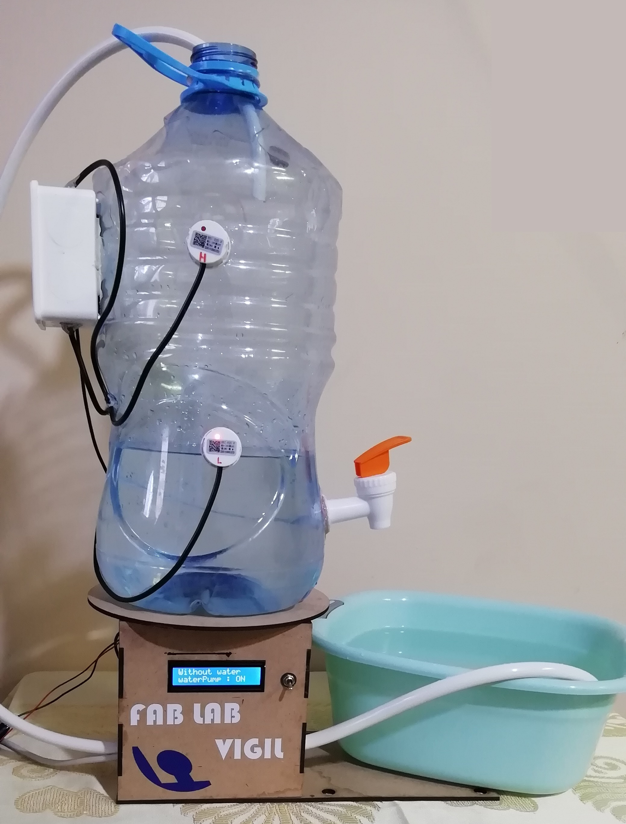
if (statusSensorL == LOW) {
digitalWrite(ledPin, HIGH);
digitalWrite(waterPump, HIGH);
lcd.print("Without water");
lcd.setCursor (0, 1);
lcd.print("waterPump : ON ");
}
if (statusSensorH == HIGH) {
digitalWrite(ledPin, LOW);
digitalWrite(waterPump, LOW);
lcd.print("With water");
lcd.setCursor (0, 1);
lcd.print("waterPump : OFF");
}
delay(100);
}
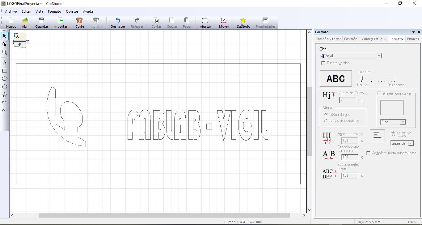
c) I also used the vinyl cutting machine.
This is the result of pasting it into the prototype structure
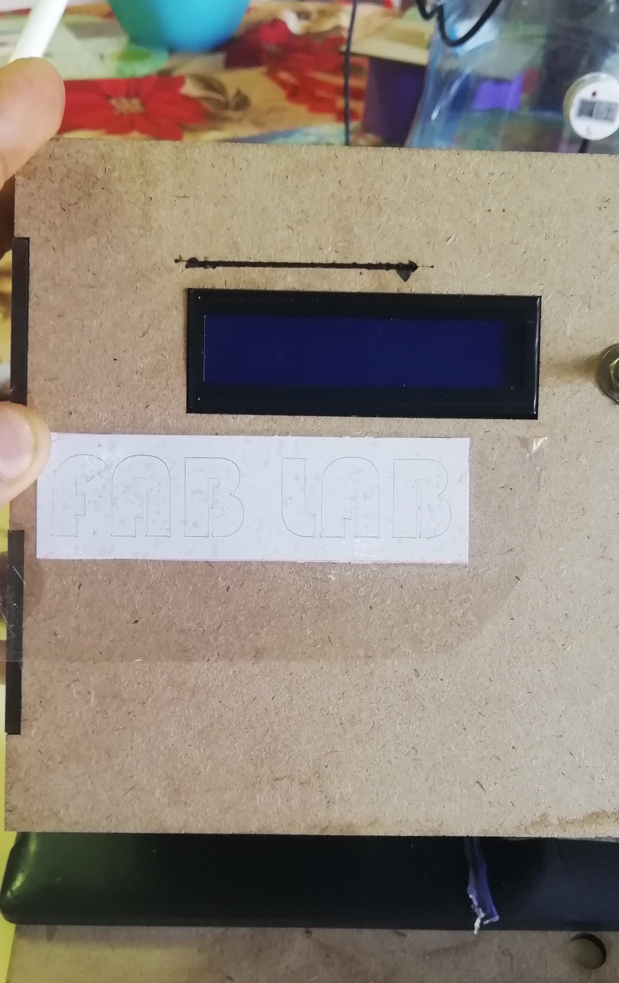
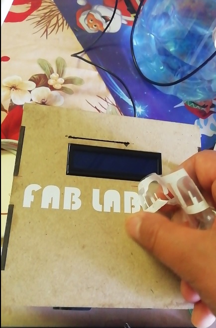
I remove the rest of the vinyl that is not used, and it is becoming attractive
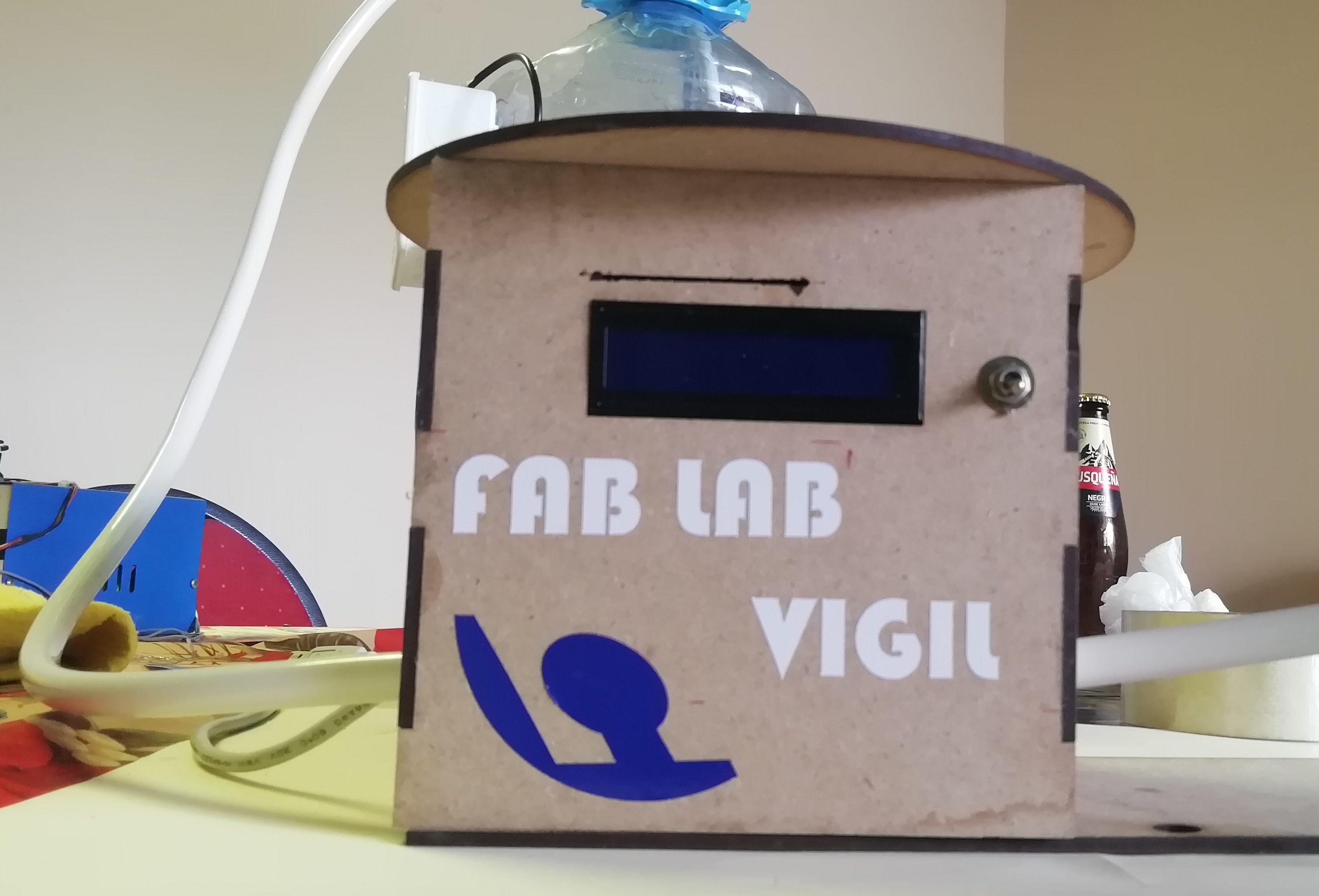
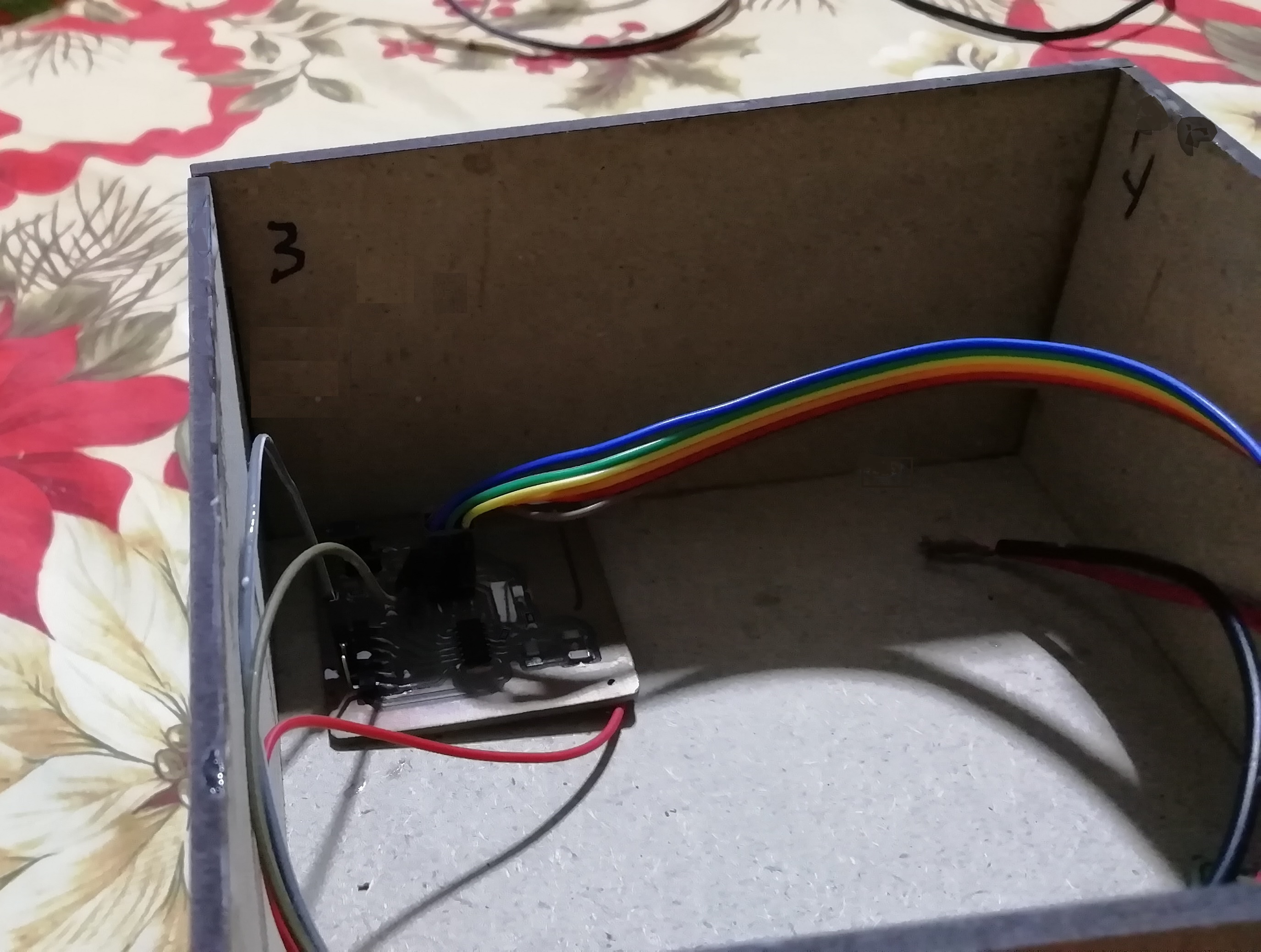
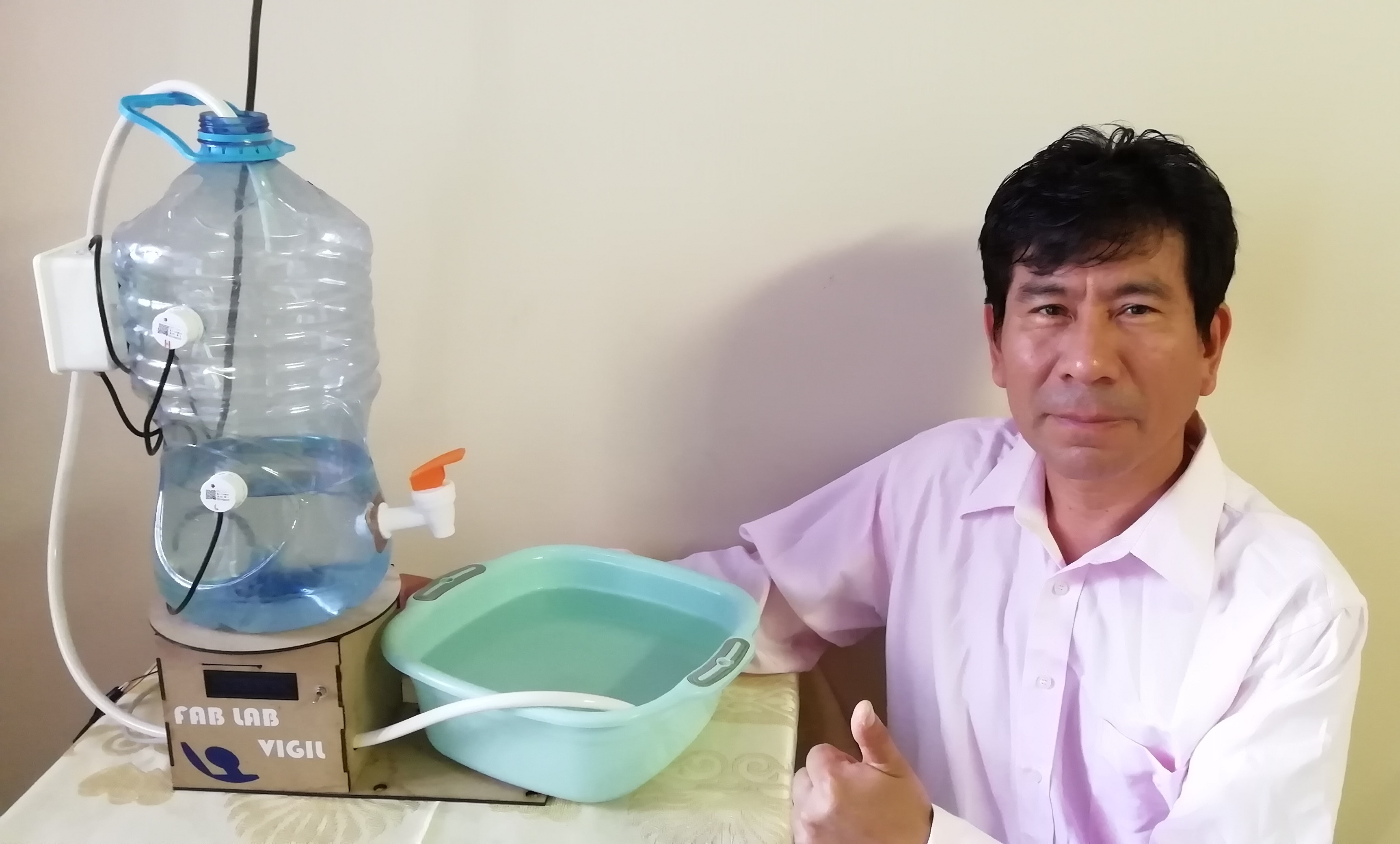
This is an image of the prototype designed and assembled.
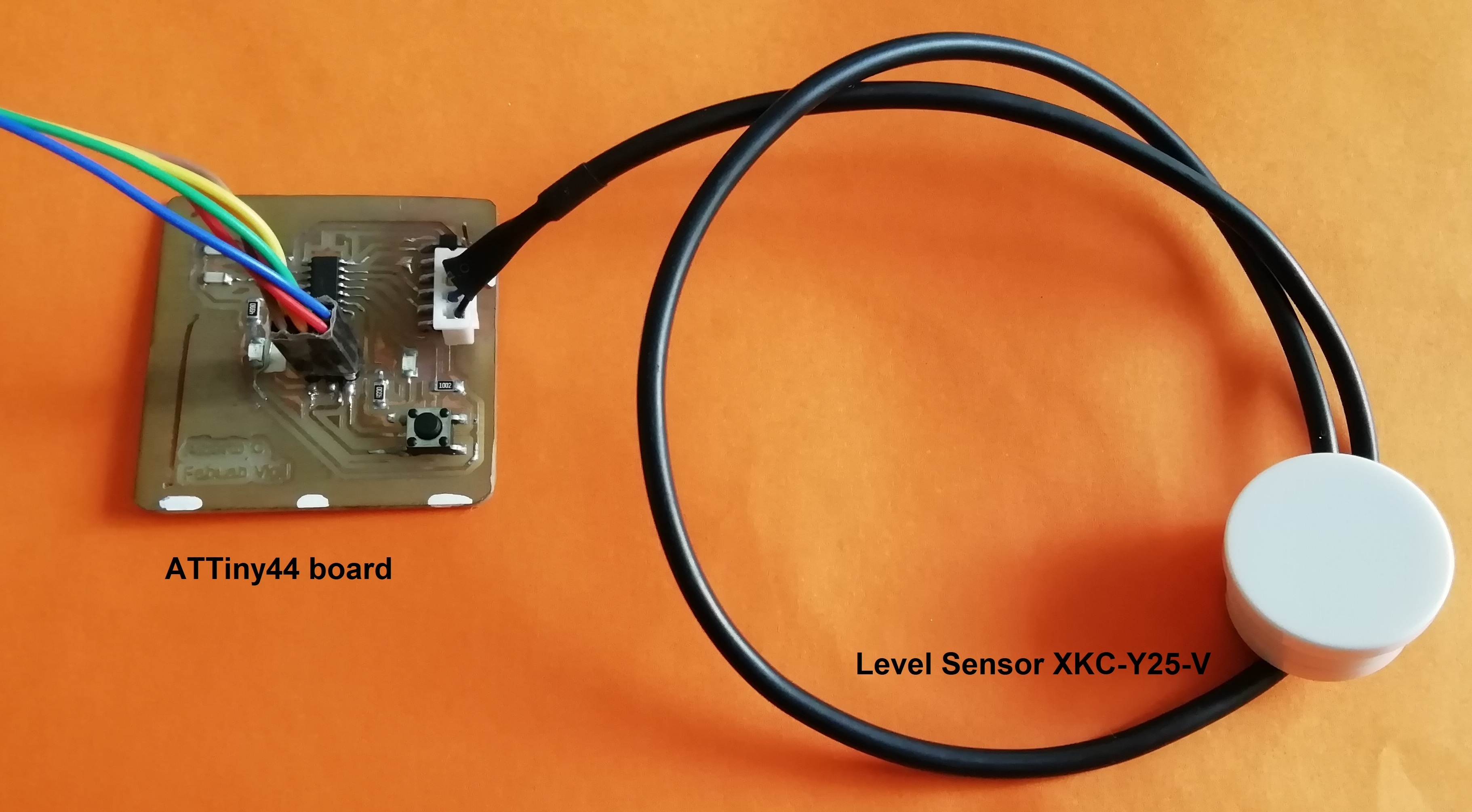
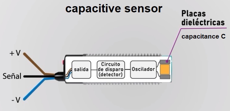
Level Sensor XKC-Y25-V:
This sensor detects the level of liquid contained in the container. It is based on capacitive sensing technology that reacts to water approaching the active surface to change its capacitance. The detection distance to a given material (sensitivity) is in the range of 0 - 20 mm.
In capacitive level detection, the capacitive sensor and the tank form the two electrodes of a capacitor. Any change in level causes a change in capacitance, which is converted into an electrical level signal.
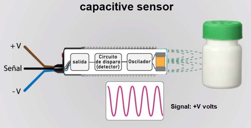
Level detection
When a liquid penetrates the electric field between the sensor plates, the sensor changes the dielectric, thus changing the capacitance value. If the capacitance is high it transmits a +V volt signal, otherwise it sends a 0 volt signal.
Internally the sensor consists of dielectric plates with a certain capacitance on the sensing face which is responsible for emitting an electrostatic field.

For more details on sensor operation, see assignment 13. Input devices.
Getting here is being a hero
Summary Slide
Video Clip
Useful links
Design Files
| Description | Files | |
|---|---|---|
| Program Final Proyects | FinalProyect.ino | |
| LOGO Final Proyects | LOGOFinalProyect.cst | |
| Base - Part1 | Base - Part 1.stl | |
| Structure - Part2 | Structure - Part 2.stl | |
| Circle - Part3 | Circle - Part 3.stl | |
| DesignPCB sch | PCB_schematic.sch | |
| DesignPCB brd | PCB_board.brd |

This work is licensed under a Creative Commons Attribution 4.0 International License.