14. Networking and communications
This week I worked on networking devices that might help out with my final project.
Task
- Design, build, and connect wired or wireless node(s) with network or bus addresses
- Group project: send a message between 2 projects.
Concept of Networking
As mentioned in the lecture, the concept of networking is required when 2 microcontrollers need to communicate to each other.
Some reasons include:
- Parallelism: Distribution of responsibilities of a large task to small microcontrollers instead of time slicing for a single microcontroller
- Modularity: Splitting tasks into logical segments, and allow them to be removed or added easily. Can help with debugging subsystems
- Interference: High power systems can potentially be noisy, and can affect the (relatively) low noise level of another subsystem. Having them communicate via wire/wireless might alleviate the issue.
Plan of attack: Wifi?
After looking at some past year assignments as well as Prof Neil’s exmaples for networking, I was particularly interested in the ESP8266-01 (or just ESP01). I had some experience with it on breadboards, and wanted to try and make a board for it. I started to think: How should I demonstrate “networking”?
The ESP01 is traditionally used to enable Wifi connectivity in Arduino projects. There is a lot to unpack in that sentence, so let’s break it down:
- ESP01 acts as a laptop “Wifi card”, sends and recieves TCP/IP packets in the Wifi Network
- Arduino communicates with the ESP01 for information it receives
- Arduino does something with the received information (light an LED, etc.)
or
- ESP01 acts as a laptop “Wifi card”, sends and recieves TCP/IP packets in the Wifi Network
- Arduino does something with some input data (from sensors etc, other serial ports etc.)
- Arduino communicates with the ESP01 to send the information
I think that either one of the flow should be sufficient to demonstrate. I chose the latter to implement for my individual assignment, and the previous to implement for the group project’s microcontroller. (Documented in group project assignment page )
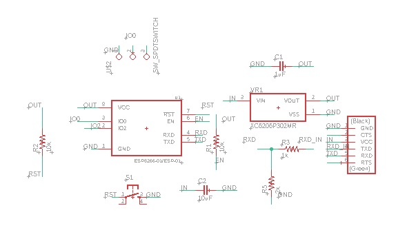
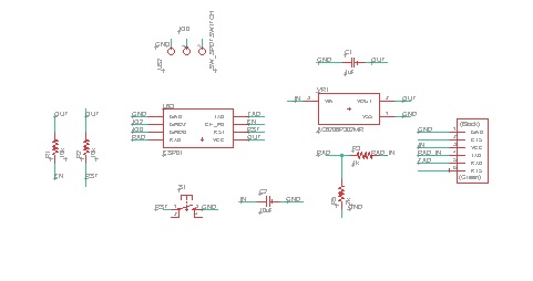
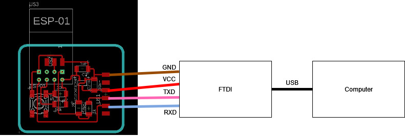
Drawing the circuit
Essentially, I looked at the circuit that Neil designed and made what I believe is a good enough circuit.
Steven showed us some ESP01 demo boards, and highlighted some differences between his board and Neil’s board:
- Steven’s board had a voltage divider between the FTDI header and ESP01 Rx. This is for ESP01 to communicate with a generic 5V FTDI compatible header, while the ESP01 is a 3.3V logic board. This also means it will lose integrity if it communicates with other 3.3V boards, there is a need to step up/down the voltage levels appropriately.
- Steven’s board had a current limiting resistor at the ESP01 Tx.
- There were no buttons or switches, all of them are replaced by normal male header pins.
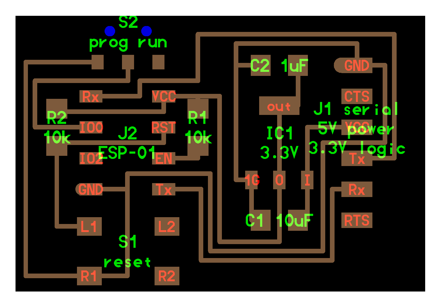
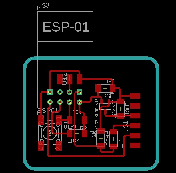
With these in mind, I picked and chose design choices that I wanted to adopt as well, and came up with my board:
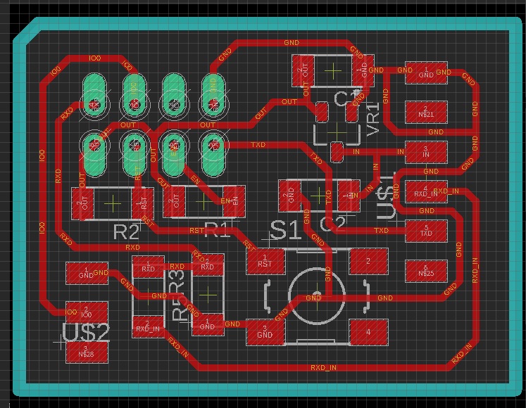
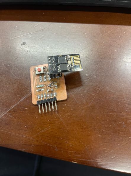
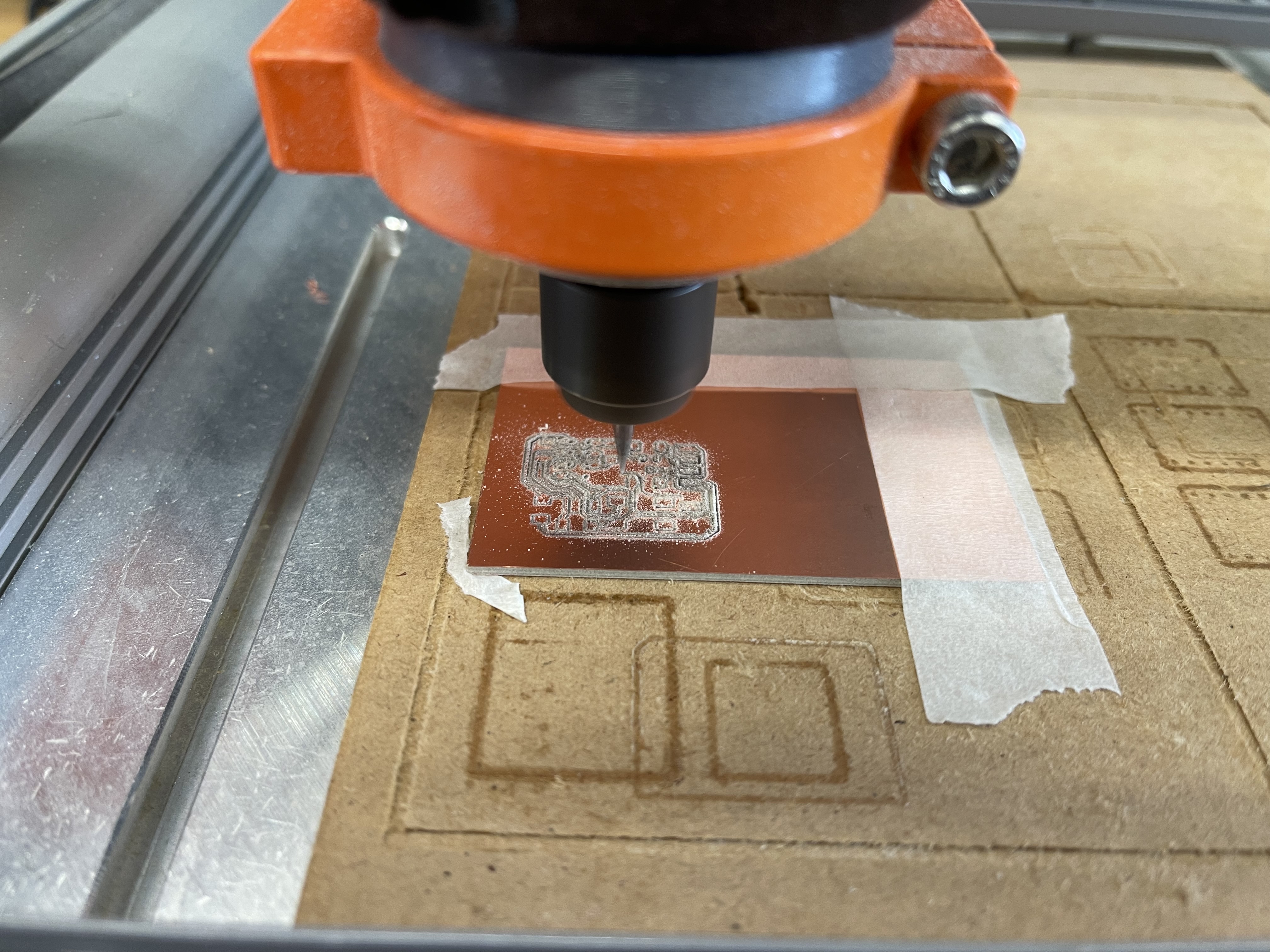
And I proceeded to mill and solder the board:
Update: Steven mentioned to us that some ESP01 board designs directly connect to the 5V of other devices. In the past there has been some hot debate on whether the ESP01 are 5V or 3.3V. In the end, the CEO of Espressif came out and mentions that the I/O of ESP8266s are 5V tolerant, but it needs to be supplied with 3.3Vs.
Update 2: Separately, Steven explains that Vin and Vout have a working range, and they are designed to have some overlap, while ensuring the input and output between same devices can communicate with each other. This explains why even though the voltage levels are different, my circuit still technically works, but for longevity of the ESP01 it is better if the devices are at similar voltage levels
Board does not work after a long time of troubleshooting
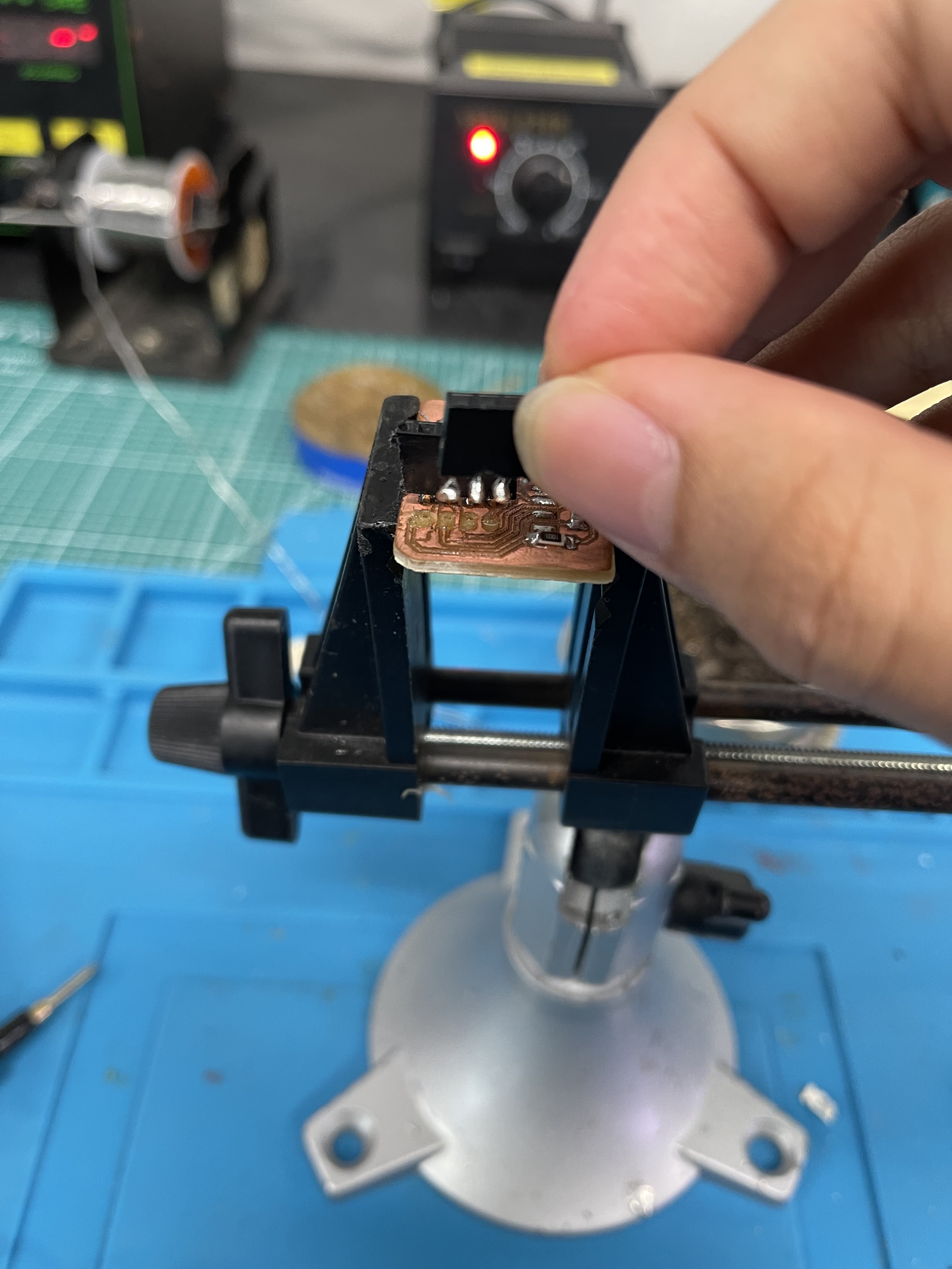
As I was very paranoid with accidentally shorting parts of the board, I tried to supply 5V directly to the pinout of the board. However, there was no power coming from the 3.3V regulator. This troubled me for many days, and eventually I sought help from Steven.
I then soldered the board and tested it. surprisingly, it power up like a charm! The way Steven designs his board is a lot more systematic than mine, and I hope to one day learn some of his skills. Furthermore, even an ameteur like me can solder the components onto the board with no issues at all!
Do something with the board
Now that I know the board is working, I then program it as if it is a Wifi Card that relays MQTT messages. To do this, the ESP01 needs to have information about my access point, as well as where the MQTT server is. This can be done by programming the ESP01 with my SSID and password. I have omitted them from the uploaded files, but you can still see them in the videos. However, there shouldn’t be any security issues, as I am using my mobile hotspot, which I periodically change its password anyway.
As a proof of concept, I set up a local MQTT broker. MQTT works as a publish-subscribe model, as illstrated below:
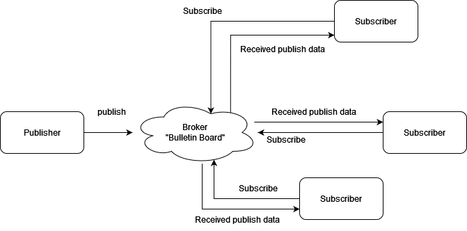
We can think of the broker as a bulletin that houses text that are sent through the MQTT protocol. Devices that can send MQTT messages can be in the form of a computer running a piece of program, a Raspberry Pi, an Arduino, ESP8266 and so on. As such, there are two ways for us to have said broker,
- Use cloud based brokers: Some examples include AWS IoT, Thingspeak, etc.
- Use local brokers: Mosquitto is a common broker for Windows
Since I want this to primarily be a local test, I want to make use of Mosquitto to run the broker.
- Install Mosquitto MQTT. Choose the installer based on your system.
- Go to the location of mosquitto installation, then run
mosquitto.exe -vto start the broker
To set up the libraires on the Arduino Side, we need to do the following instead:
https://github.com/plapointe6/EspMQTTClient
Results
In the video above, you can see that the ESP01 has been successfully programmed and connected to my mobile hotspot. I entered some numbers via Serial Monitor to the ESP01 as a form of hardware Serial communication. When ESP01 receives Serial information, it sends it to the MQTT broker via the topic attiny1614/led. Note that although it is named as such, there is no involvement of attiny1614, but rather a preparation for my final project. Then, I used mosquitto_sub.exe to subscribe to the topic attiny1614/led and I am able to receive messages.
To show that messages are indeed transmitted via MQTT via ESP01, I disconnected my laptop from my mobile network, after which regardless what message I entered into the Serial Monitor, it does not appear in the mosquitto_sub.exe window.
Contribution to the group project
To complete the group project, I hooked up an ESP32 module with a blink code that also listens to attiny1614/led, and when it receives this information, it will blink an RGB LED. Instead of using mosquitto_pub.exe to publish the blink interval, I instead send it through ESP01’s Serial Monitor.
Details on how the ESP32 is set up can be found at the group assignment page.
Hero shot of project