Omniwheels
From week 2, I have made a mecanum wheel that is fully 3D printed with PLA. The wheel works pretty well (all things considered).
The issue with this wheel is the amount of time that is required to make one, as well as how intricate each small part is. I have tried to simplify the wheel as much as I can, but it still takes around a day to print and assemble a wheel.
Then, I started to consider omniwheels. These are wheels with smaller wheels on the side that rotates normal to the axis of rotation of the larger wheel.
I first started designing this and hoped that it can be printed in one go. I was not successful, but I wanted to keep printing in place as a proof of concept of the wheel
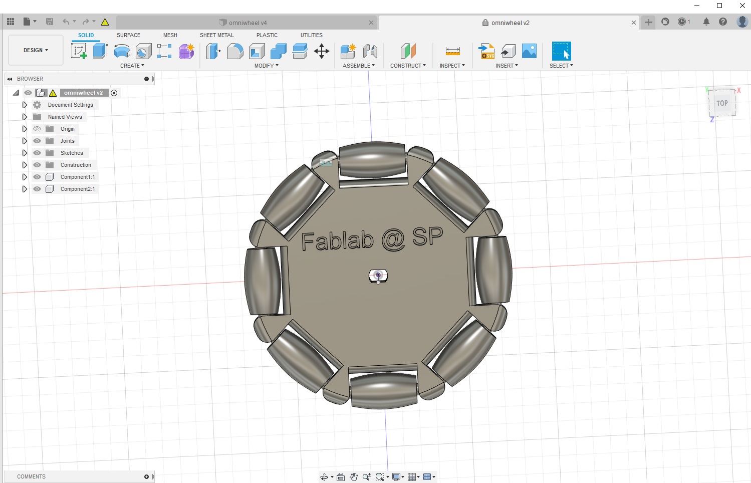
Then, I noticed a big portion of the wheel is actually not utilized. This led me to wonder how much “small wheels” do I actually need.
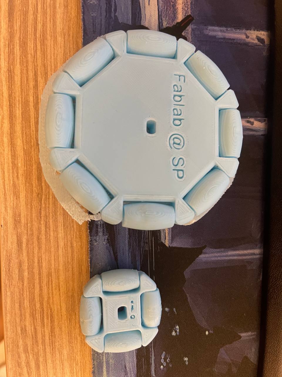
Compare the two, we actually noticed the smaller the wheel, the less space I have to work with, meaning the samller wheel is not very efficient. Furthermore, the wheel might look a bit boxy, and doesn’t really work wheel as a “rolling device”.
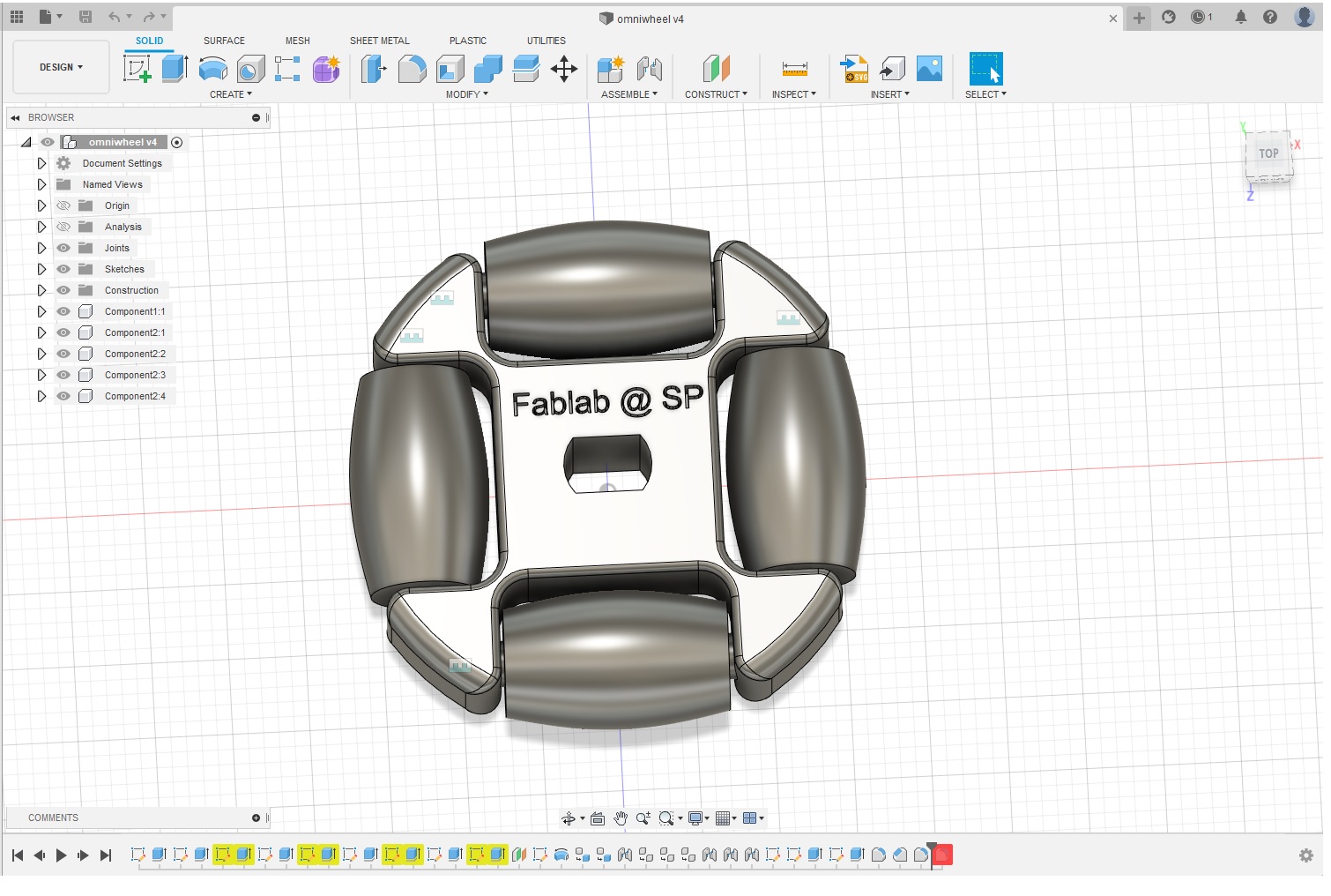
Therefore, I decided to do 2 things to my design
- Make the wheel hub as small as possible, and supports as thin as possible.
- Make the small wheels as large and “buldgy” as possible, to make
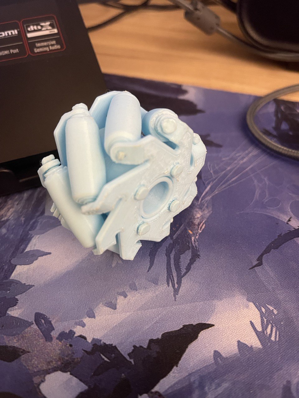
Hence I came up with this design
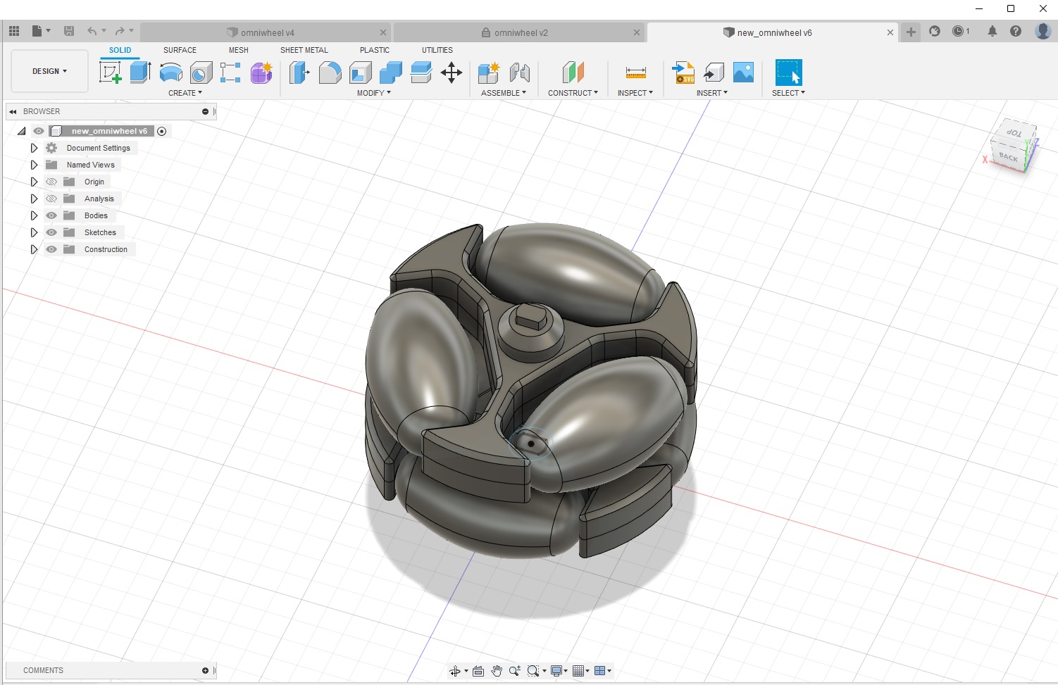
Coincidentally, many omniwheels on the market do look something like this.
I fitted these on a small robot platform (with 3 TT-motors and a basic robot chassis).
This is the video of the robot driving. The motion is timed PWMs, so it looks a little bit jerky.
Printing small wheels with TPU
After consulting with Steven, it would be better if I printed the axis separate from the actual wheel. Printing this axis proved to be challenging, as it is very thin and small. Steven also suggested I experiment with Tree support, which was recently graduated from Experimental features in Cura.
I asked around some settings on TPU. I wanted to try printing with TPU, but the Fablab did not have the settings tuned yet. As such, I set out a journey to print TPU on my Monoprice Mini Select V2.
I found a reddit post and video that uses the exact same printer I was using, as well as their settings.
https://www.reddit.com/r/MPSelectMiniOwners/comments/a4xlgf/tpu_on_mp_select_mini/
I also watched several youtube videos about TPU, and came across MakerMuse’s video about it
The key takeaway I had was that TPUs have different flexibilities, summarized in the table below
| Brand | Flexibility | Elastic | Stringy | Easy to print? | Others |
|---|---|---|---|---|---|
| Polymaker | High | Low | No | Yes, can print on Prusa i3 Mk2 | |
| Generic TPU(?) | High | High | Yes | Yes, but needs to be slow (especially at infill speeds | |
| Fiberlogy FibreFlex | Very High | Medium | No | Yes, can print on Prusa i3 Mk2 | |
| Essentium TPU | High | Medium | High | Specialized extruder hardware required | |
| MakeShaper TPU 85A | High | Very High | Low | Yes, can print on Prusa i3 Mk2 | Very squish, but with parts with form it is solid |
| Diabase Flexion | Very High | Very High | No | No | Ridiculously flexible (borderline skin soft), extremely stretchy! |
Based on the specs, I think what I need was something like Polymaker’s TPU, as MakerMuse also used it for his off-road robots. That being said, time and availability is not on my side, therefore I opted to try something that is available locally.
Eventually, I stumbled upon a seller on Carousell that sells ZIRO filament, it’s supposed to be a very budget option (perfect for a student like me :)) I also found a video that had a good review on it.
Update: The seller did not have TPU. I looked up Lazada for TPU.
Some other suggestions I got: Print the wheel in two parts, then superglue the two parts together. TPUs work well with superglue
Experimenting with infill types
As I was asking around the Fablab and scouring the internet for advice on TPU, one thing in common is to increase flowrate and decrease print speed.
For the experiments below, I had to ensure it could print, before being able to characterize the print itself, therefore I went with a ballpark figure first as demonstrated in this video:
| Name | Value |
|---|---|
| Flow rate | 132% |
| Speed | 18mm/s |
| Nozzle temperature | 220 deg celcius |
| print bed temperature | 50 deg celcius |
| Retraction speed | 40mm/s |
| Combing mode | ON |
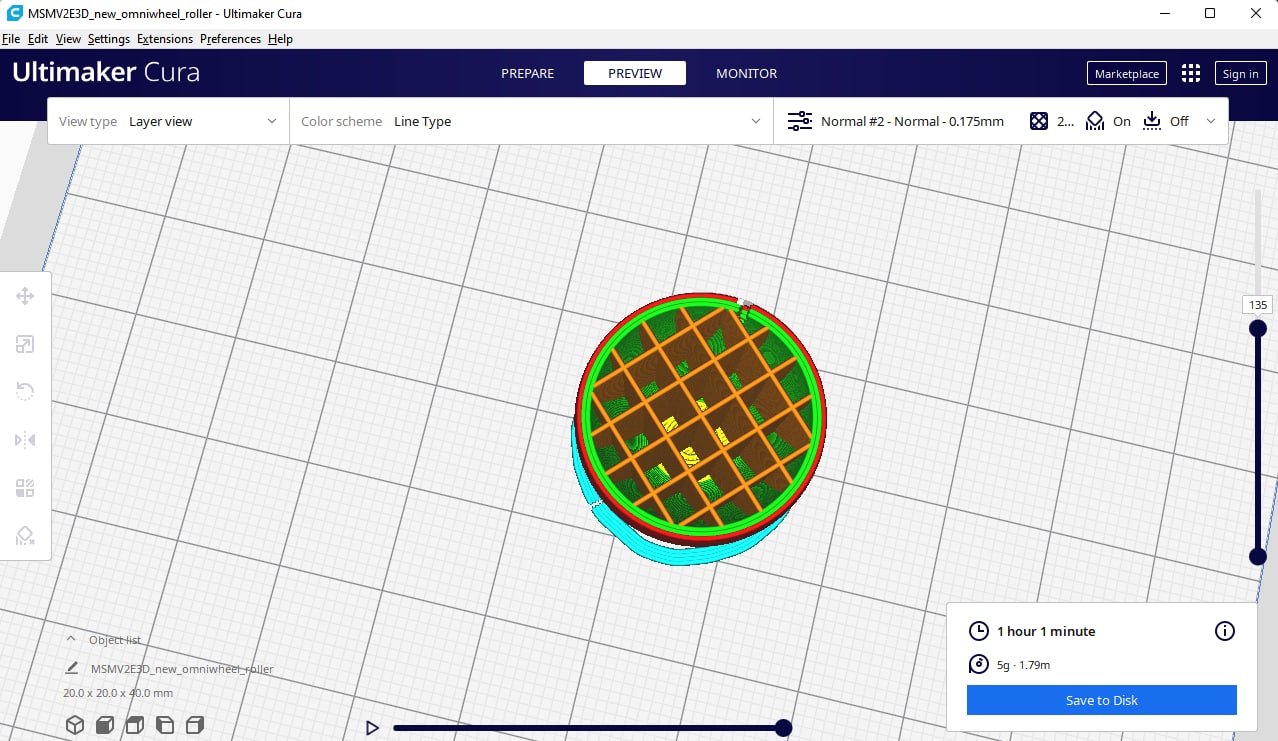
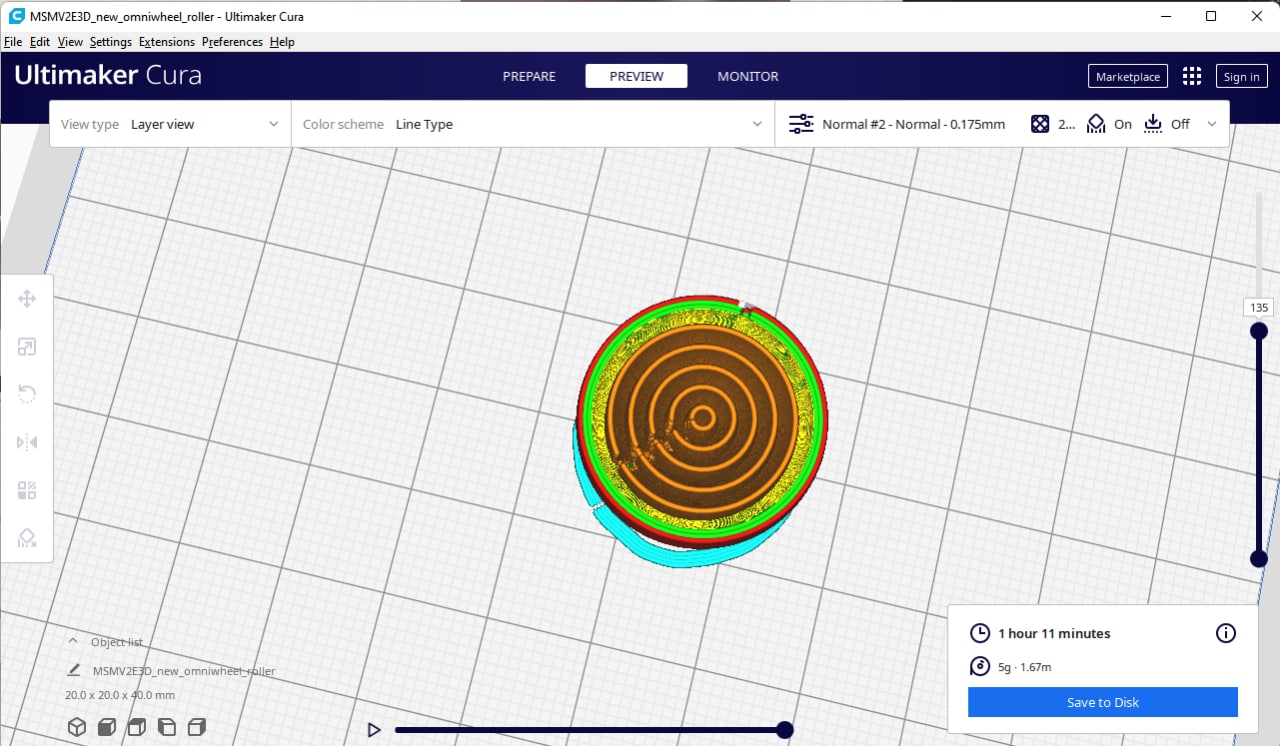
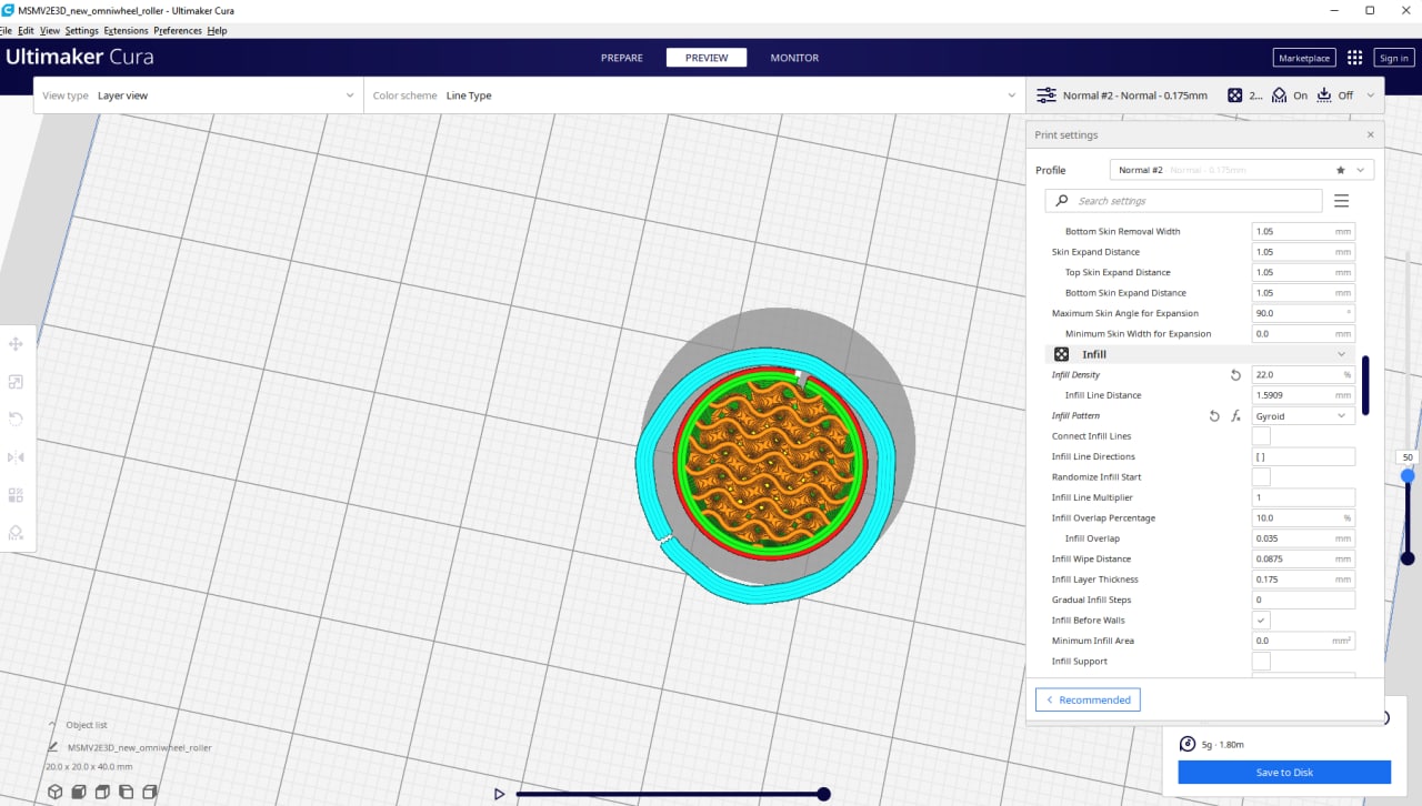
Showcase of Grid vs Concentric vs Gyroid:
| Type | Density | Description |
|---|---|---|
| Grid | 22% | Stiffness is uneven; some parts are harder than some others |
| Concentric | 22% | Stiffness is even; however, it is too squishy (might not be able to hold the entire robot’s weight) |
| Gyroid | 22% | Stiffness is even and moderate |
Based on the descriptions, I decided to print with Infill of Gyroid at 22% Infill density as it feels the most sturdy and even on all parts of the surface among the threee I have tested.
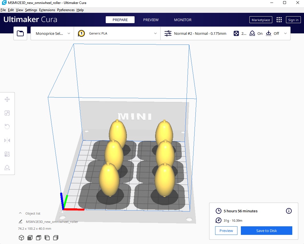
Printing
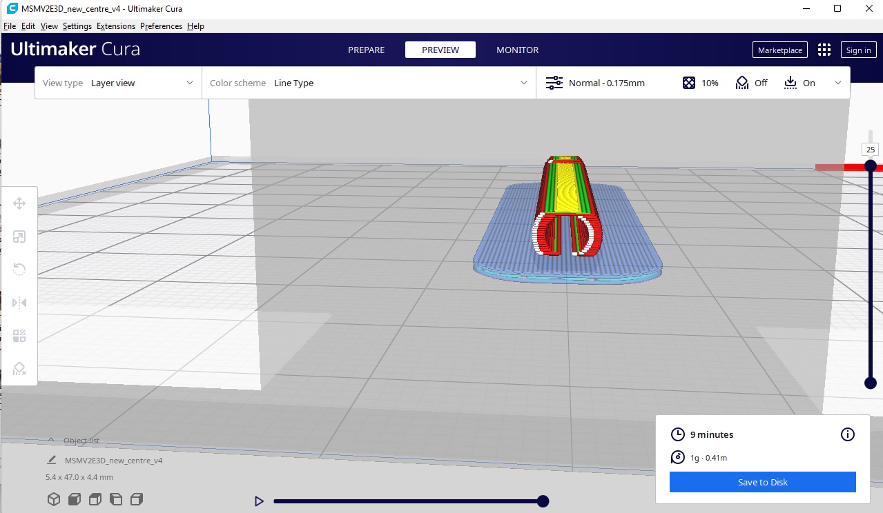
For TPU, it is actually better to print a part at a time. As such we need to set that in Cura as well.
And the Slicing would look different
Linking the stepper motor with the omniwheel
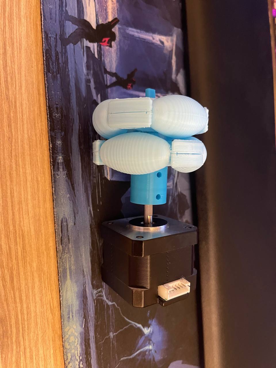
I wanted to reduce reprinting as much as possible. I want to keep this wheel frame. After again asking Steven on his take on how to link those two parts, he suggested me to print a coupler to link the D shaft with the shaft on my wheel.
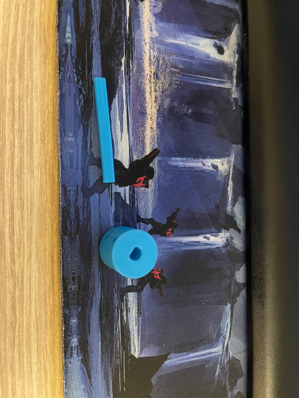
I did a test fit, seems to be working fine.
Testing characteristics
Problem 1: Skid
After attaching the wheels on the robot, notice that PLA is very slippery, and the robot skids most of the time. This is not ideal. In contrast, having the TPU wheels makes the robot much grippier, but is difficult to rotate around the axis. We need to sand it a bit to achieve better clearance.
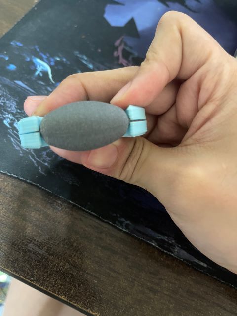
The solution is to sand the axis with some sandpaper.
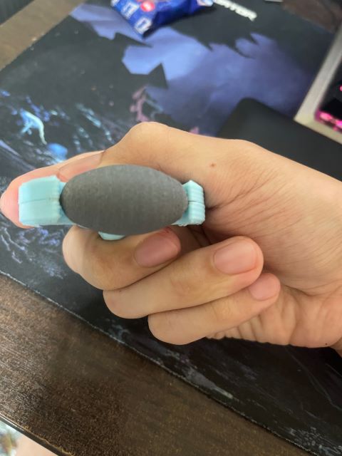
Solution: After repeating this for all 6 wheels, the robot will be able to move a lot better.
Problem 2: Not stable
The robot doesn’t seem to be able to support a lot of weight. As I press it down with my hand, notice that it has a lot of give, which I think will be the first part to fail when load is added on the robot.
After consulting with Steven, he states that the reason is because the axle connecting between the wheel and the 3D printed coupler is PLA. Given the thickness that is printed, it is not strong enough.
Solution: replace the axle with metal rods (can be bought for cheap at Daiso/hardware shops)
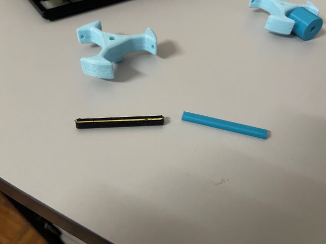
As I was back in Malaysia, I had easier access to hardware shops. There, I found 3.2mm copper rods for around RM6 per meter, which is roughly USD 1.40. I also got some bolt cutters and cut the rods to roughly the same length as the original axle.
The question now is: How do I replace the axle with the copper rod?
The solution was simpler than it seems. After further inspection in my cad, I noticed that I could technically fit a 3.2mm rod in the axle itself! Therefore, the axle can be reinforced with the rod that way.
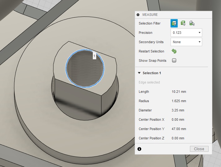
When slicing, I had to make sure that the very thin layer at the top has its path generated.
With that, I test fitted, and indeed most of the flex has gone away after this modification!
Final result
After painstakingly printing 18 wheels (with a lot of fails as well… T.T), I replaced all the PLA wheels with TPU ones, and applied fixes to the 3 identified problems. The problems have been reduced, but I think to completely eliminate them, I would need a better mechanical design than what I currently have. Regardless, I think this is sufficient for this particular spiral, as I only need the motors to move, and the robot to be able to move in all directions, albeit some errors here and there.
Files
- omniwheel step