11. Output devices
This week I worked on some output devices.
Group Assignment
We characterized servo motors, and calculated its peak power, max sustain power and min sustain power at rest.
Plan
- Add an output device to your microcontroller
- Program it to do something
Task
After thinking about what I wanted to do for output devices, I wanted to keep it simple. On my microcontroller that I have made in week 6, it had an LED. Next, I had also exposed all the pins of the ATTiny1614. Therefore, I wanted to do something with the both of them.
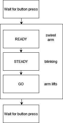
After some deliberation, I wanted to do a simple “Ready, Steady, GO!” sort of system. This is how it works:
- Initially, the LEDs are off and Servo is at position 0
- Wait for button press, when the button is pressed
- LED lights up dimly, and Servo rotates by roughly 3-5 degrees, then back to 0 degrees.
- LED starts to blink at higher and higher frequency for 2 seconds
- LED lights up completely, and Servo lifts up completely
- Waits for button press to reset.
Design
My instructor, Steven gave us 2 types of servos, 1 is continuous and 1 is positional. I will only use the latter, which is positional
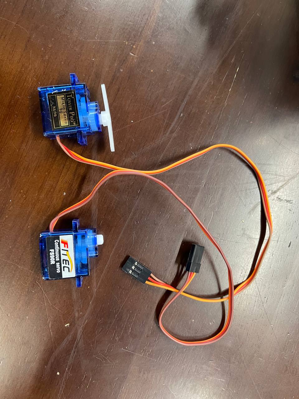
The working principle behind is that there is a controller that reads a potentiometer within the Servo. The position of the Servo is dictated by the pulse Width Modulation that was provided to the controller.
To see if this works, I decided to write an equivalent code that produces these PWM pulses. The snippet below shows setting the servo at 90 degrees
#define EXPECTED_PERIOD 20000 //microseconds
#define NINETY_DEG 1500 //microseconds
...
void loop() {
    ...
    waitTime = EXPECTED_PERIOD - NINETY_DEG;
    for(int i = 0; i < 50; i++) {
        // servo keeps at 0 degrees for 1 second
        digitalWrite(servoPin, HIGH);
        delayMicroseconds(NINETY_DEG);
        digitalWrite(servoPin, HIGH);
        delayMicroseconds(waitTime);
    }
...
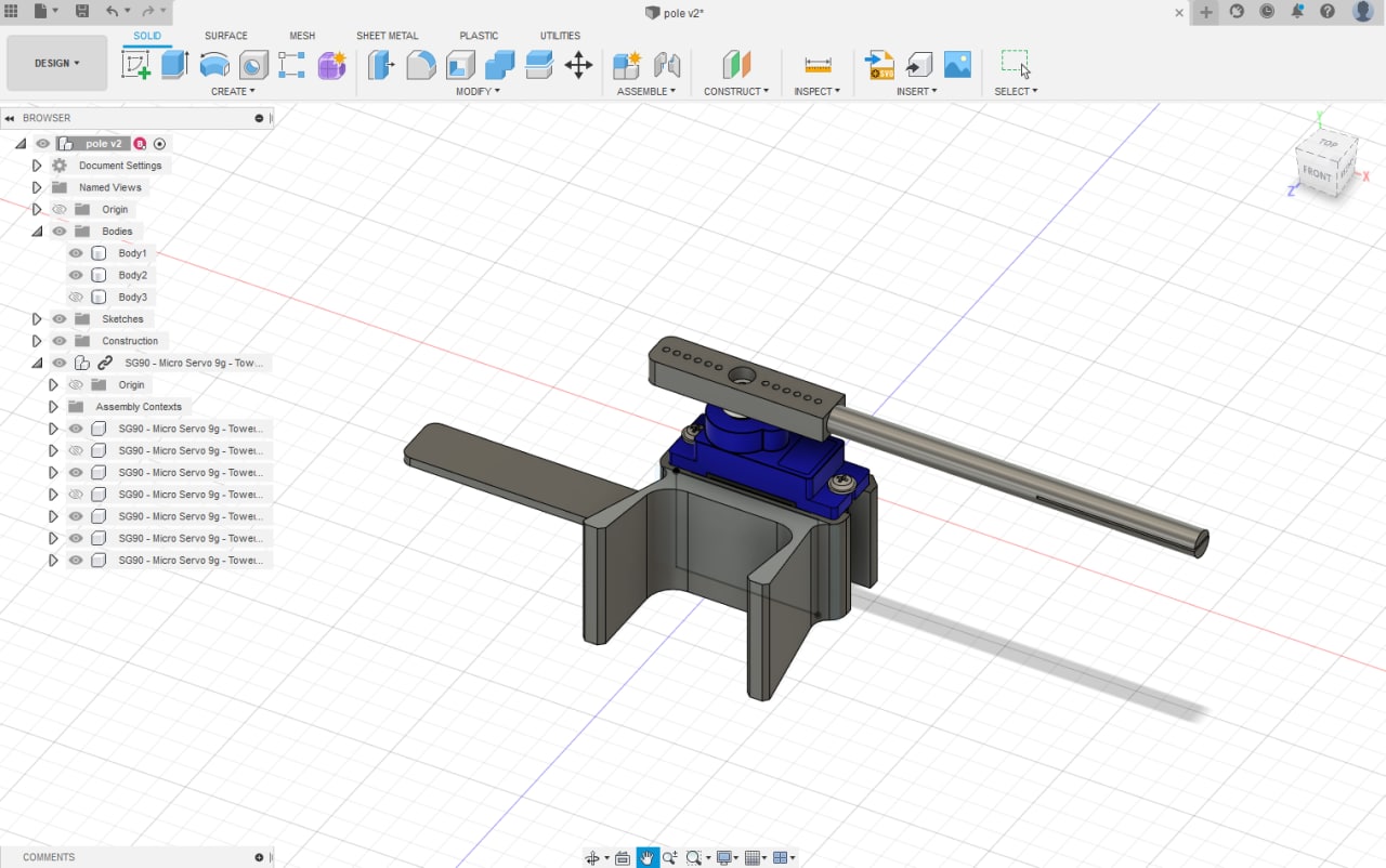
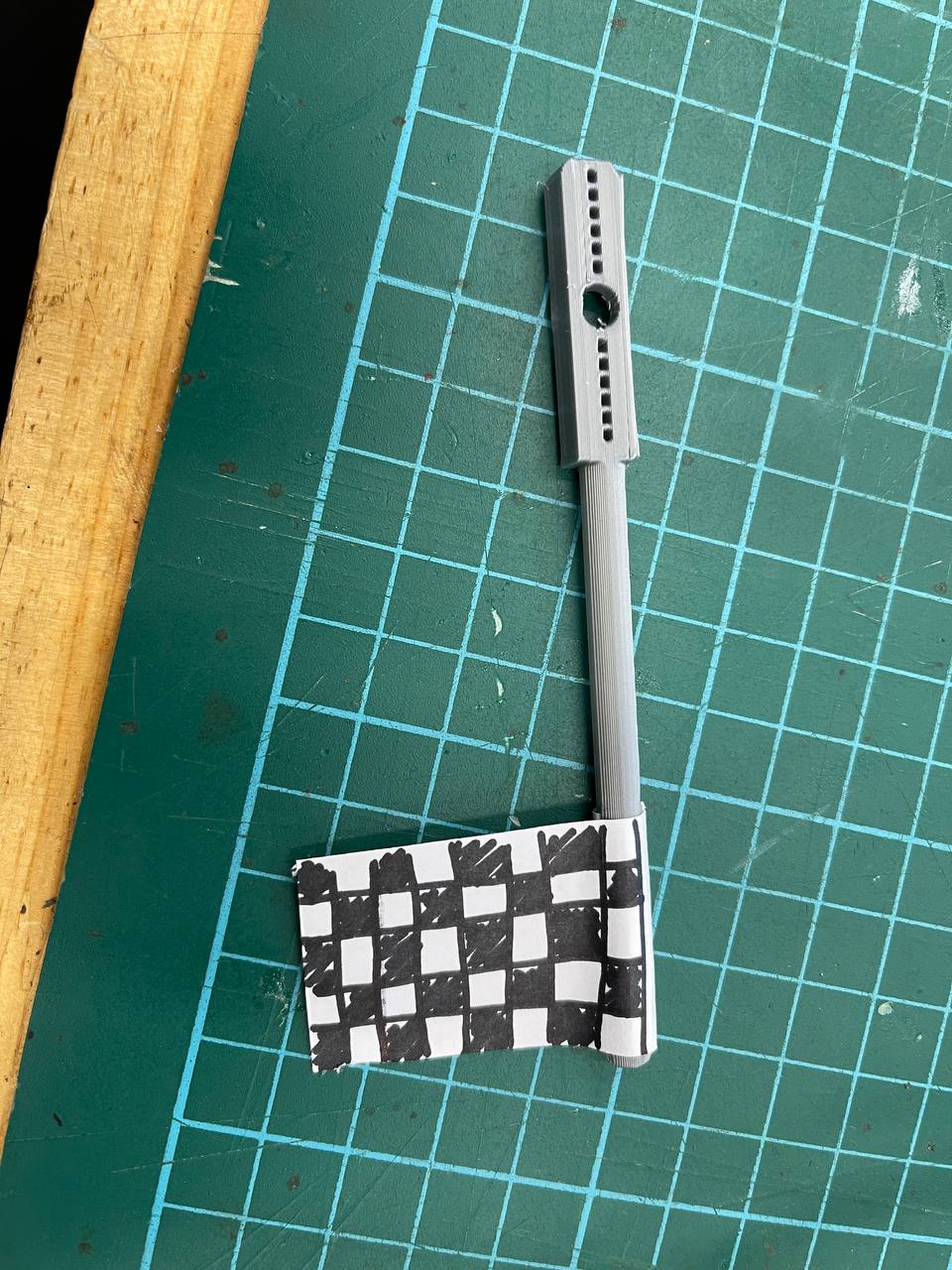
Next, I made a simple design that represents a pole/flag for the “READY STEADY GO!” portion.
This is a demo of the arm moving 0-90-180-90 on repeat (note: it is very similar with group assignment)
After understanding the underlying principle, I then moved on to use the simpler, abstracted logic of Servo library.
Logic
The logic of the code was pretty simple, I implemented a blocking wait for the button, and run the routine at bullet point 2, then implement another blocking wait, and the ATTiny1614 will run this continously.
Assembly
Lastly, I assembled everything and we’re done!
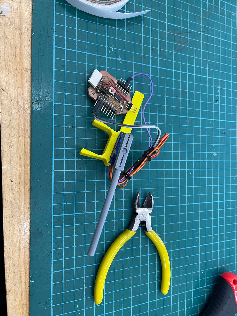
Hero Shot
That was fun!
Conclusion
Output devices bring a lot of machines/toys to life. I believe the underlying concepts of moving motors etc will help with projects in the future.