4. Computer controlled cutting
This week I worked on using the vinyl cutter and laser cutter as prototyping tools.
Characterizing Laser Cutter
View here for group assignment page
I have learnt that laser cutters are very powerful devices, and especially in Singapore Polytechnic, it is a widely use resource. The parameters we can tune with are Power, Speed, and DPI.
The supplier has provided quite a comprehensive list of parameters we can set on our own. However, some of the parameters might be damaging to the machines in the long run. For better longetivity, we need to be aware of the Power and Speed parameter. We should not set it to be 100% as much as possible, and attempt to work with the other parameters to balance out the load.
An analogy that our instructor, Mr Steven, gave really sticked with me. The general idea was that if the printer was a runner, imagine power and speed parameters as the amount of effort an athelete exerted. If the athelete is sprinting at 100% all the time, it would not be sustainable for the runner.
As much as possible, we should balance out the effort exerted by the laser cutter to ensure that the printer is in good shape after we have used it.
Important results
The value for kerf from our characterization was 0.18mm on Epilog Fusion Pro.
The settings that worked for us were as follows:
| Power | Speed | DPI |
|---|---|---|
| 20-30% | 60% | 300PPI |
Parametric design for Laser Cutting
After learning how to characterize Epilog Fusion Pro found in FabLab Singapore Polytechnic, I decided to have a swing at parametric design.
Firstly, I had a concept in mind of how it should look like. Initially I wanted to be ambitious as the past year students of Fab Academy, specifically Nadieh Bremer. The issue was that I was not familiar with how the different parts should come together in the first place. Given the amount of time I had, I decided that a spiral development approach was necessary.
- Think of a simple design to be fabricated
- Identify repeating elements within design
- Identify how to create bigger components from basic components
- Explore at least 1 of the more “complex” joints mentioned in class
- Laser cut the result
- Assembly
The above steps can be simply repeated a couple of times for spiral development, modifying the first step and think of a more complex design
Design in mind
Initially I wondered if it would be possible to make something like how Nadieh Bremer did. However, I felt the creation to be a great undertaking. As such I decided to simplify it to be just be a collection of surfaces, let’s start with a table of some sort.
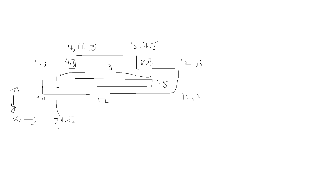
After defining that it would be a table, I quickly sketched out how I can make repeating elements. Firstly, I need to make a rectangular plane, and from that rectangular plan we can attach different sizes of them to form surfaces. The basic element of this rectangular plane is a square. As such, I sketched the idea I had in mind in GIMP.
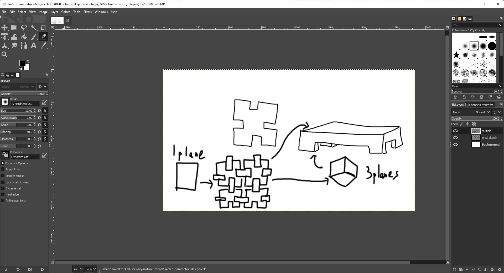
Minimally, the feet of the table can be stable with just 3 planes (2 if we use the top surface as well). A plane can be created with a few repeating pieces that fit together nicely.
The table will have an aspect ratio of roughly 4:5 , and the feet can be 1 unit high as a prototype.
Onto Fusion360 to CAD
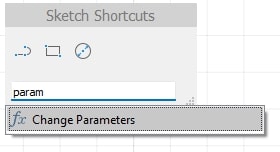
To make the design parametric, I pressed the search hotkey s and entered parameter and found the tool Change Parameter.
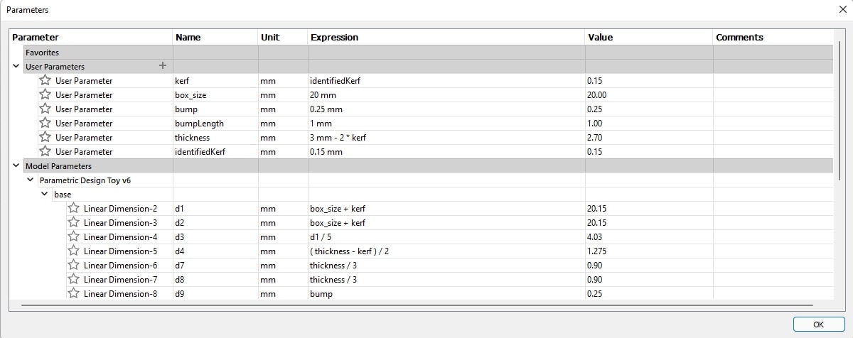
Click the “+” symbol beside the “User Parameters” table. I added some parameters that I think will be useful for my design, like kerf, box_size, thickness, and later added bumps in attempt to have a stronger connection between pieces.
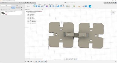
Before I apply the parameters to the design, what I did was CAD the outline out first, then entered parameters and even formulas to define how each side, slot, corners should look like. The process was very enjoyable, as I could see what was going on as I changed the parameters.
From CAD to Laser Cutter
Initially, I did a roundabout way to export my sketch. I learnt that we can make a sketch from a surface in Fusion360, then save that sketch in Fusion as a dxf file. This dxf file can then be read by CorelDraw, where we can export it to different Laser Cutter Firmware.
Here, we also have other brands of laser cutters. While during the characterization step we were working on the Epilog Fusion Pro, the individual assignment was done on the Universal VLS 6.60 75W laser cutter. Hence, I have to do a test cut first before doing the final cut, as there might be some differences between the machines.
Update to Gobal Eval
In order to use the laser cutter, the parameters from grp project still applies. The workflow is generally the same:
- Import
.dxfinto CorelDraw and export to the laser cutter control software - Apply lab tuned settings to cut cardboard
- Use auto-focus and set the Z height to be the material’s thickness
Our lab is lucky, as we have the technicians to manually calibrate focus of the laser using specialized tools during preventive maintenence. Therefore, for users all we need to do is to enable auto-focus and set the thickness of the material in the software.
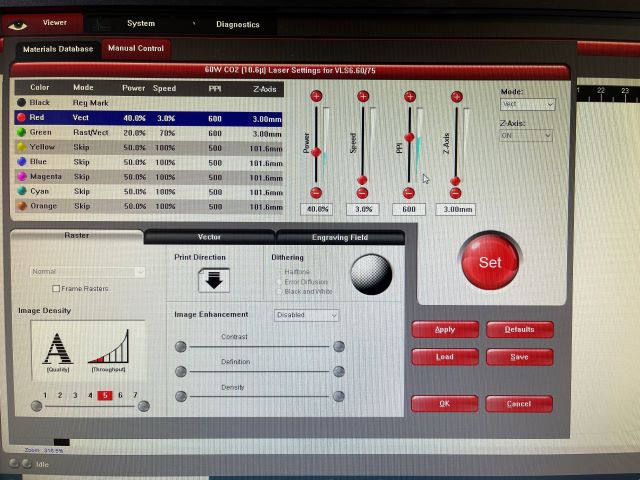
This is a screen shot of the Universal VLS’s software, the parameters shown is to cut acrylic (which is most used in the lab)
This is a screen shot for Epilog’s Laser Cutting software to cut cardboard from our group assignment page
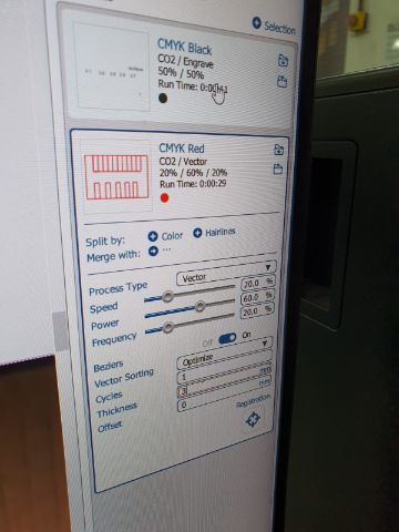
Some important parameters to change:
- Speed: decreasing this parameter increases depth of cut. Decreasing this also makes the job slower. Change either by entering manually in the textbox or changing the slider
- Power: increasing this parameter increases depth of cut. However, having power be at 100% can lead to part failure at a much faster rate. Change either by entering manually in the textbox or changing the slider
- Frequency/PPI: The setting
Freqencyin Epilog’s Laser Cutting software is analogous to thePPI (Pulse Per Inch)setting in Universal’s Laser Cutting software.Frequencycontrols the pulse duty cycle of the laser. If we set the Frequency to100%then the laser will be always on while cutting, and25%means that it will be on 25% of the time (across a second). PPI follows a similar explaination where a particular frequency (say 300 for cardboard) is applied on 1 inch distance. Change either by entering manually in the textbox or changing the slider
End update
I did an initial cut, and find that despite having a slope for easy fitting of two pieces, the slot was still too hard to place into each other. Luckily, I have used parameters for it, and I simply increase the distance for the slope, and it got a lot better! Although the difference was invisible to the human eye, we can really feel it when we are putting the two pieces together
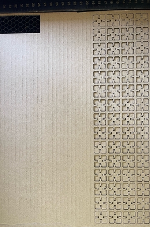
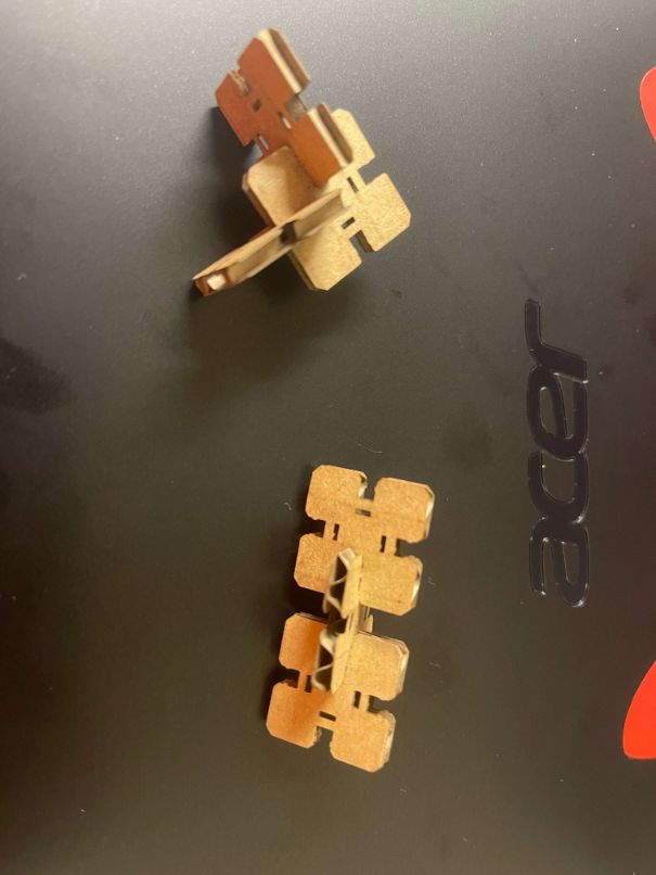
Something that I did not expect was the effectiveness of the small bump which theoretically should act as a clip does in fact work! Again, it was not very visible to the human eye how it would help, but comparing a side without the bump (through repeated removal and placing back of said pieces), I could tell that the side with the small bump has a tighter fit. This would definitely be a design consideration for tight-fit models in the future
Bloopers:
I had 3 bloopers when doing my laser cut. When I set the laser cutter to cut, I bumped into the table where the computer controlling the laser was attached to while it was cutting. As such, the cut was stopped, possibly due to an unstable connection.
Next, I did a second cut. As it is currrently the assignment submission season in Singapore Polytechnic, the laser cutter is quite tightly booked. With the previous blooper, I was quite nervous as to whether I could complete my work on time. As such, I set a new location on the material to cut, and immediately hit the Start button. As I looked at the first few cuts, I noticed it to be slower, and the cuts were browner, which was when I noticed that the settings were at the default settings. I immediately hit stop and changed the settings before cutting again.
Lastly, after changing the settings, I started the cut. I “attempted” to follow a guideline set by my instructor, but somehow there was a misclick on the keyboard… I wanted to set the power to 60%, speed 30% and PPI to 300, but instead set the speed to be 3%! Luckily, I stayed near the printer while it was cutting, and quickly noticed that the laser head was moving slower than before, and quickly stopped the cut. Indeed, the part that I was cutting was starting to burn up. I waited until the material stopped burning before proceeding with the correct settings.
Moral of the story: Be very careful when using the laser cutter. Do not expect things will go correctly. Develop an SOP in the lab or personally follow one, and stick to it! This ensures minimal accidents to happen. Lastly, stay near your machines while it is operating!
From Laser Cut to Assembly
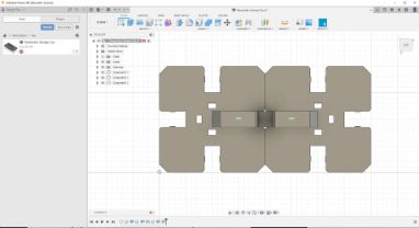
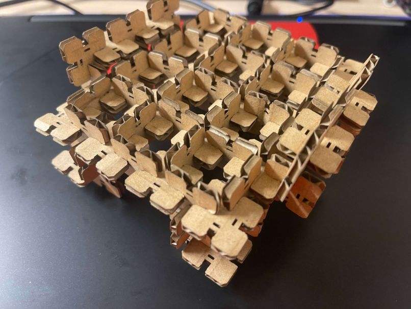
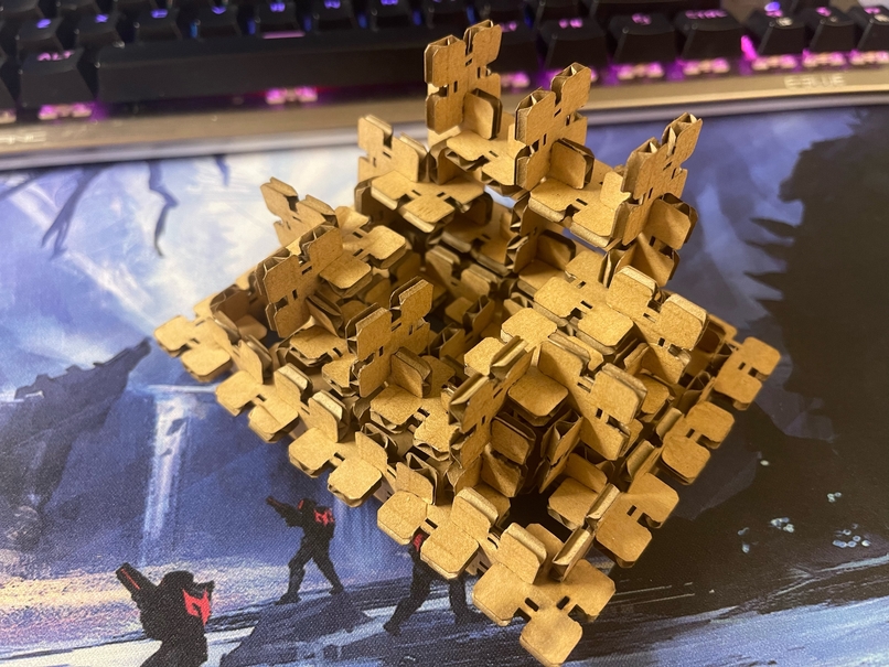
The reason why I designed the parts these way is due how flexible it can be: as long as we can represent our creation in terms of surfaces, we can create a simple construction of it from these small pieces that I’ve laser cut. Below is an example of the table model according to my sketch above.
Vinyl Cutting
Next, we learnt about what a vinyl cutter was. In Singapore Polytechnic Fablab, there are a few Silhouette Cameos available. We learnt to use the Vinyl Cutters as well as what is possible through the use of Vinyl Cutters.
Design
Similar to Laser Cutters, I initially wanted to do something very ambitious. However, I wanted to start from something small. As such, I took some PNGs online and created a simple logo.

One thing that I wanted to explore in this cut was whether it would look better as just the black lines or should the black lines be instead removed and left with the white lines. This would be a matter of choice, when I have the vinyl cut in hand, so I proceeded with the vinyl cut.
Using Vinyl Cutter
To use the Vinyl Cutter, we need to install Silhouette Studio. One thing that I think users should be aware of is to select their OS correctly (most laptops or desktops should be using Windows 64-bit), as it defaults to Windows 32-bit.
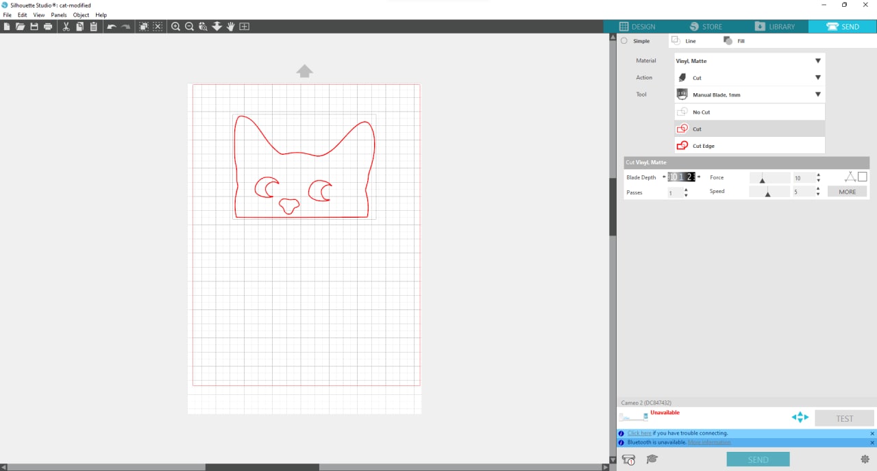
The cut settings were
| Parameter | Value |
|---|---|
| Force | 10 |
| Speed | 5 |
| Index | 1 |
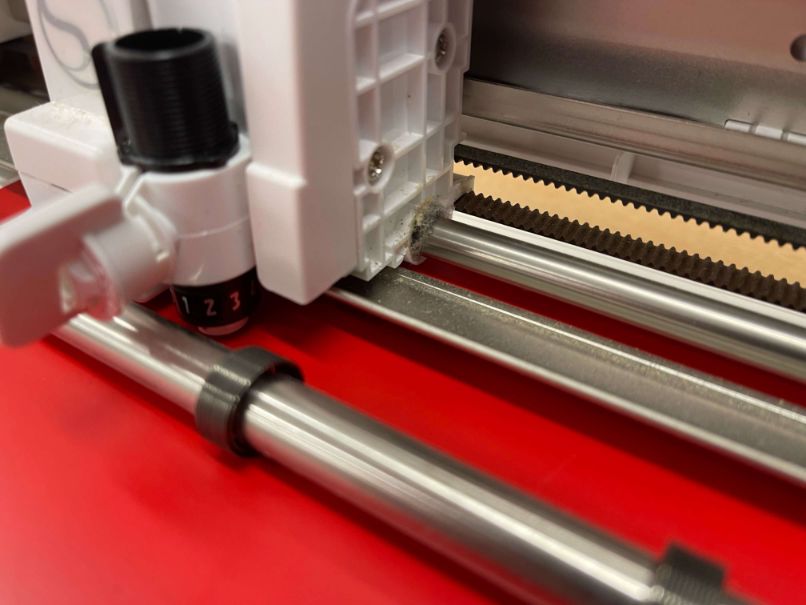
Index is the number on the tool of the machine, and it should match with what was set in the program.
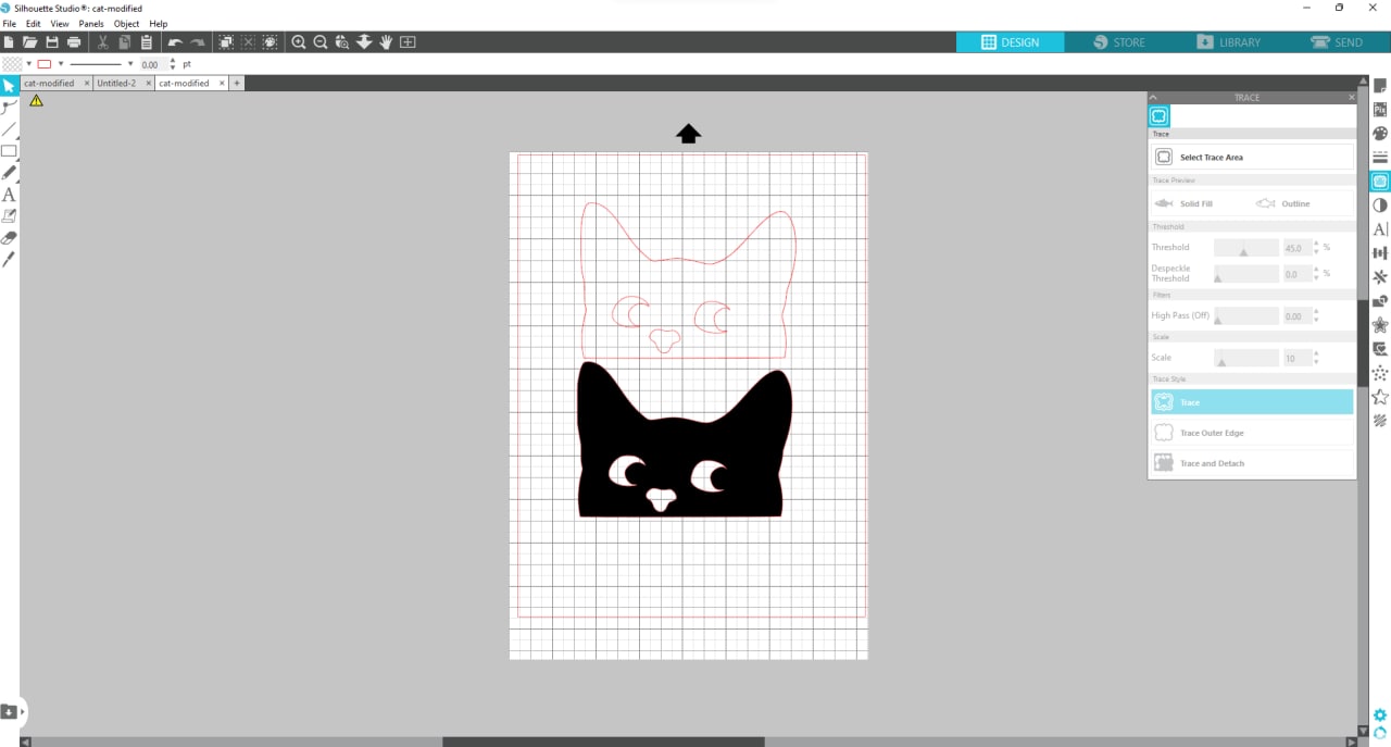
The general steps are as shown:
- Setup cut area
- Import images
- Select Trace Area
- Adjust Threshold and Despeckle Threshold
- Connect Printer and auto install drivers
- Select correct cutting material (This part is important for setting up cutting profile)
- Adjust knife of Cameo (This step is important before cutting!)
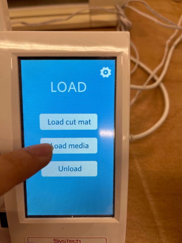
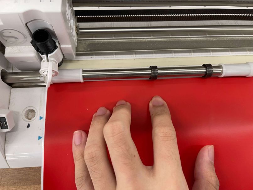
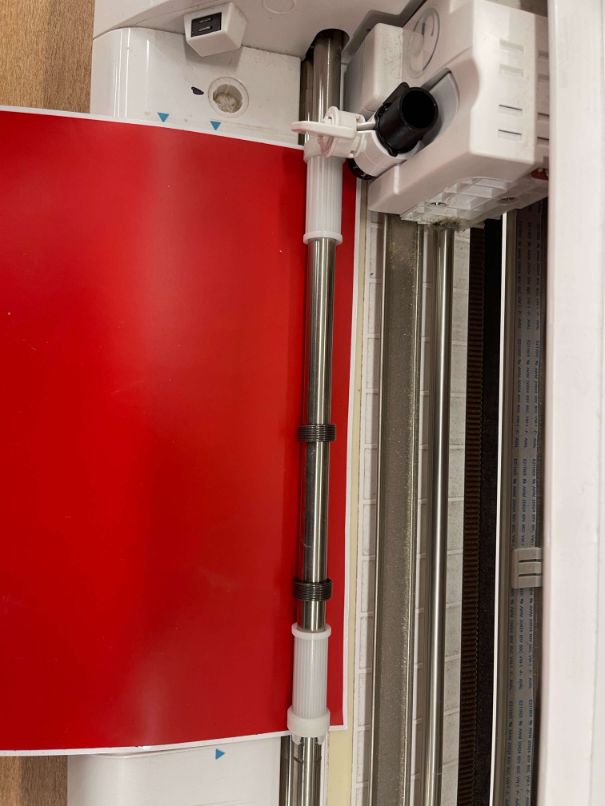
- Load cutting material
- Start cut job
- Unload cutting material
- Weed vinyl cuts
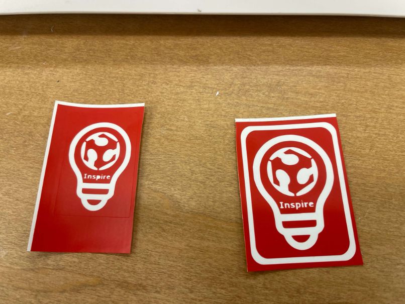
Below is the result of cutting
Result
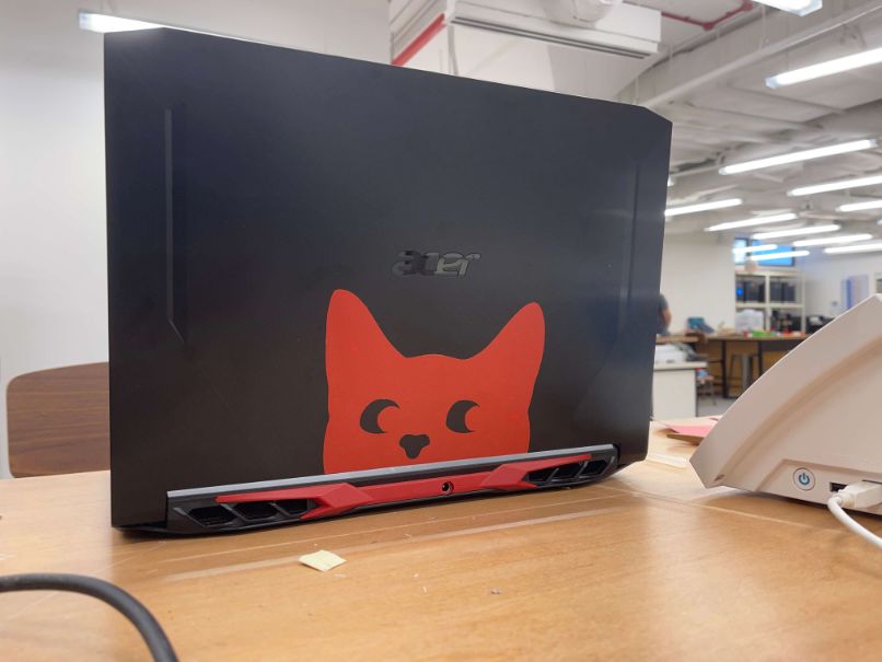
My first cut was considered not very successful, as it is not possible to weed the letters properly due to how small they are. As such, I scaled up the same image, and added a border around the image. I decided to remove the black lines, and what was left was supposed to be the actual logo. I liked how it look, and would explore the Vinyl Cutter more in-depth in the future
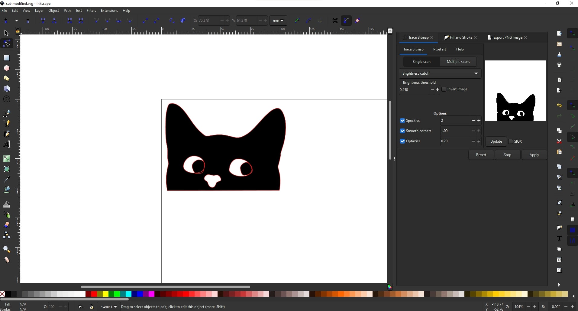
Next, I wanted to cut something a bit bigger. In my case, I decided to try out this Cat image that I found online. The difficulty was how I should handle the eyes of the cat, as it is separate from the image. I had two choices:
- Add lines to connect the eyeballs to the side of the eyes
- Edit the image itself
I personally do not find having the eyeballs with lines connecting at the side of eyes to be attractive, so I decided to edit the image. A simple edit as moving the eyeballs to stick to the side of the eyes in my opinion preserved the asthetic of the image, and made the cat even more curious :)
Design files
Parametric design
- Parametric design file: parametric-design-toy.f3d
- Parametric design cut file: parametric-design-to-cut.dxf
Vinyl Cutting
- Curious cat modified: cat-modified.svg
- Fablab Inspiration: vinyl-test.svg
Extra exploration (To be done next week/future weeks)
This section doesn’t exactly contribute to the weekly assignments, but contains explorations that I want to do for the different machines, tools, software etc. for the following week.
Live Hinges
I personally really like the concept of live hinges, as it not only looks cool, but also makes a supposedly stiff material seem almost like fabric.
This part was not completed due to the high demand of laser cutter as it is the assignment season for Singapore Polytechnic students. More will be added in the coming week.
- Design of Live Hinges
- Verify that Live Hinges work
- Trying design on a different material
- I tried living hinges on 3mm plywood
(23 Feb 2022 GMT+8) Update on what was done for living hinges
I got so curious as to how does one make a living hinge, so I decided to spend some time on this, as this week’s assignment is relatively short
Idea: What I essentially did was use the Cadquery GUI editor to automatically view my design after each change. This makes debugging my code easier, as I don’t have to boot up FreeCAD or Fusion360 everytime I want to verify if it works.
To install cadquery and the gui editor, I did the following in my conda environment
conda install -c cadquery -c conda-forge cq-editor=master
Next, I looked around the documentation for a easy start. I figured since I came from Fusion360, to make things easier I should try and represent my thinking from there in Cadquery. I went on to make an initial sketch.
As for abstraction, I chose to represent a line as a numpy array. Numpy arrays allow for easy manipulation such as list = list + 1 causes all elements in the list to increment by 1. This therefore becomes an important abstraction in the code.
Lines can be drawn on a plane, and at the end of the points, it will go back to the first point (close()). This means that the lines are stored in a plane,and different/disjoint lines can be continually drawn on the plane should we supply the coordinates to draw onto.
How should we generate living hinges? Well, similar to how you would in Fusion, you would repeaat certain pattern in 1D or 2D! This was the next abstraction, linear_pattern and rectangular_pattern. Basically, we need to tell the program what to repeat, and how many times. Each time a pattern is offset by the coordinate_shift given, until the target number of repeats is reached.
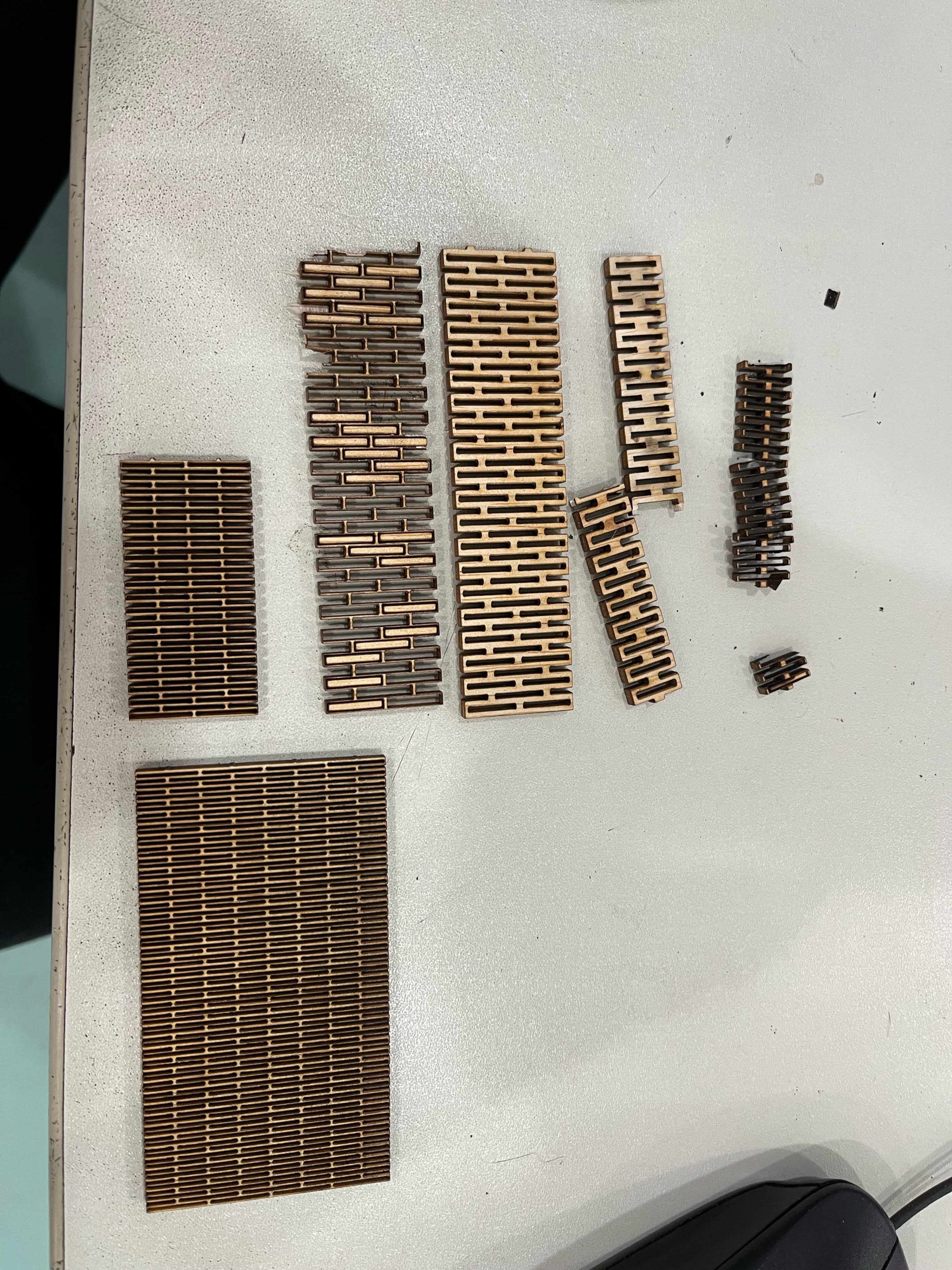
And basically that was how I generated my living hinge. Later on, I went to the 3D printer, with some kerf values in mind, I wanted to experiment with certain values.
- outer width: 12, inner width: 11.5, outer_height: 0.8, inner_height: 0.3
- outer width: 12, inner width: 10, outer_height: 4, inner_height: 2
- outer width: 12, inner width: 11, outer_height: 4, inner_height: 3
- outer width: 12, inner width: 11, outer_height: 3, inner_height: 1.75
- outer width: 12, inner width: 11, outer_height: 2, inner_height: 0.5
- outer width: 12, inner width: 11, outer_height: 2, inner_height: 0.2
One interesting thing about these values is to notice that the inner height is meant to be small, and the outer height should be relatively short as well! This is for a frequent short amount of material removal making the living hinge more flexible. Less frequent and the outcome will be more stiff.
Initially, I suggest to use cq-editor to edit the parameters. However, as the number of holes increase, I suggest steering away from the editor and instead approach in a headless manner. For my program, do the following to generate a new STEP file
python generate_living_hinge_v2.py 10 4
Here is an image of the process mentioned above
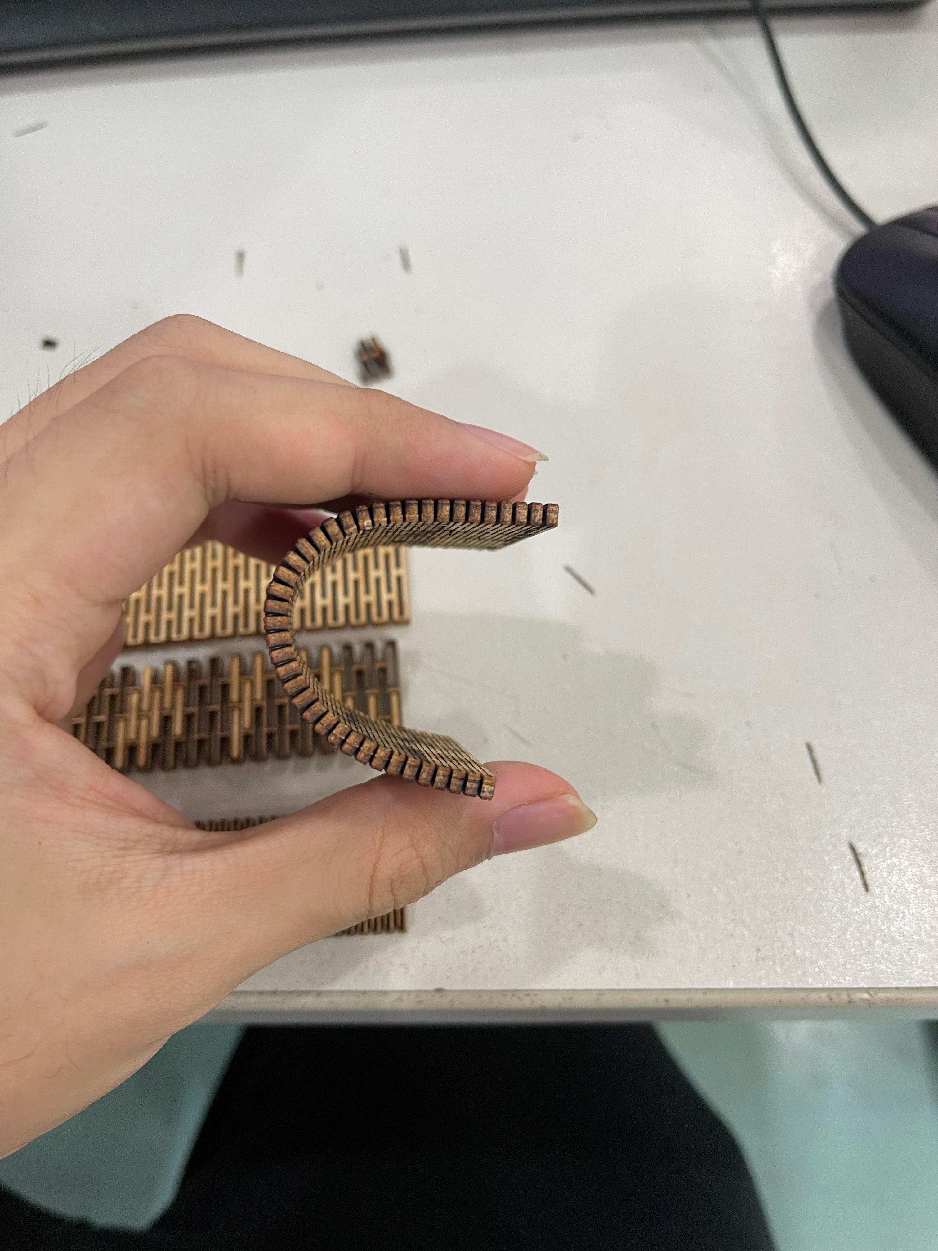
This is the final result, it is able to bend like this and return to flat with no problems at all :)
I’m not familiar with Cadquery’s available APIs, and honestly I didn’t know where to start, therefore I might have reinvented the wheel. Nonetheless I felt that it was a great exercise, and I can definitely see its potential in creating more complex shapes.
See the full documentation for Cadquery here: https://cadquery.readthedocs.io/en/latest/
Click here to return to week 4 documentation.