13. Input Devices
This week, I explored on Ultrasonic Sensors
Task
Measure something: add a sensor to your microcontroller board
Group Assignment
We learnt how to read the readings of a potentiometer. I have learnt that sensor readings may not be 100% clean. Even though we were reading the potentiometer readings directly, there are a lot of noise in the readings. If we were to put some form of threshold to the sensors, we need to take noise into consideration. This extends to almost all digital and analog sensors.
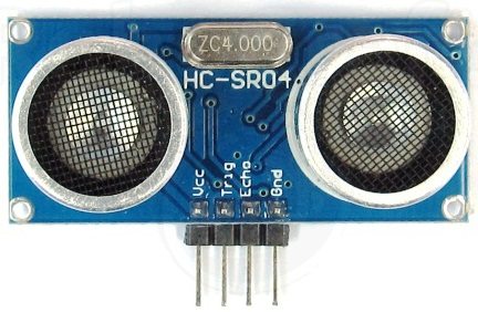
Sensor to add: Ultrasonic sensor
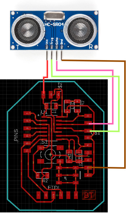
This sensor will be important in my final project. As per my fabricated board in week 6, it is able to connect to an ultrasonic sensor as I have expanded all the ATTiny1614’s pins.
I have connected the ultrasonic pins to PA2 and PA1 on my board.
THe working principle behind an ultrasonic sensor is it’s trigger pin and time to reach echo pin.
The trigger section of the sensor creates a sound wave that should be received by the echo section of the sensor. The time it takes to reach the echo pin is to be checked in program.
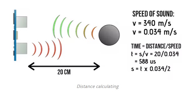
Assuming that the sound wave generated moves at the speed of sound, we can easily compute the distance travelled based on how long it took to reach.
s = v * t
the actual distance between the sensor and the obstacle needs to be divided by 2, as it a round trip back to the sensor (travels to the object, and reflect back to the sensor).
Circuit Diagram
Results
Above video shows that the values are indeed changing based on the distance travelled. Calibration would be necessary to reach a 100% accurate result, but for now just a difference in distance should demonstrate the distance calculated to be correct.
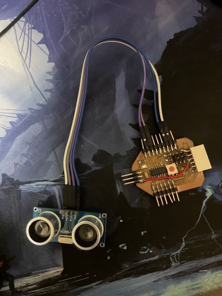
To see the results, I connected the TxD and RxD of the arduino to the FTDI board from week 4.
Files
- ultrasonic test code .ino