Chassis
To design the chassis, I had a few ideas in mind, namely a circular design, a triangular design, or some sort of a hybrid.
How was it designed
I added some basic parts into the drawing, which are:
- Stepper motors
- Omniwheel
- 18650 batteries
- My PCBs with their dimensions
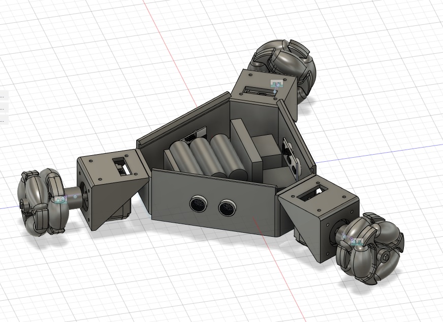
Electronics Component box
I considered a long time before deciding on this particular design. Initially, I was thinking of having the components to be at the top. However, there comes a problem where the robot’s height increases. There seemed to be less space at the bottom. Perhaps we could put batteries down at the bottom, and the top will be the components? What if we could combine these two together?
With those questions in mind, I set out to create the chassis that can fit everything at the bottom
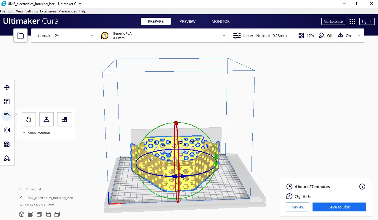
3D printing this would’ve taken 12.7 hours, yikes!
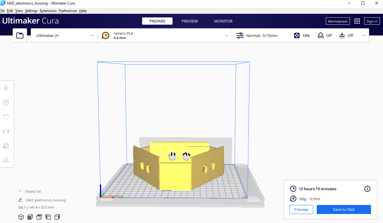
Fortunately, Louis was there and he suggesting various Cura settings that reduced it to under 4 hours!

| Parameter | Before | After |
|---|---|---|
| Wall thickness | 0.2mm | 0.6mm |
After discussing with a previous year graduate, Louis, an idea popped up when thinking about how to reduce the weight of the robot. Essentially, we can use hexagons, which greatly reduces the weight of the robot with the benefit of improving mounting of hardware within the chassis as well.
Regardless, I think I will consider details of reducing the weight in the next spiral. However, I did like the idea of having easy mounting points, so I took that suggestion and hoped to expound on it if I ever redesign the chassis.
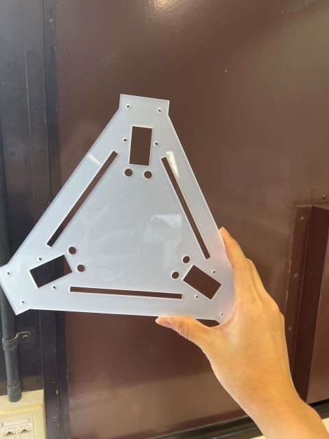
Connecting the Steppers and Chassis
Again, this was a bit challenging. I was going back and forth between having more material strengthen the robot as well as having less to reduce the weight of the robot. For the first spiral, I figured that a single piece of 5mm acrylic should be able to hold the components and steppers in place.
Here is the result of laser cutting with similar parameters from Computer Controlled Cutting week:
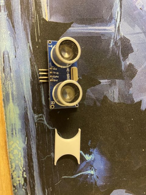
Issue: Ultrasonic sensors do not fit in the holder
Apparently, the ultrasonic sensor provided had a slightly smaller gap compared to the models online. This forces me to reprint a chassis with a more accurate ultrasonic sensor gap.
I tested the gap by printing a small test print as such
With that, I redesigned the chassis along with some of Louis’s suggestions.
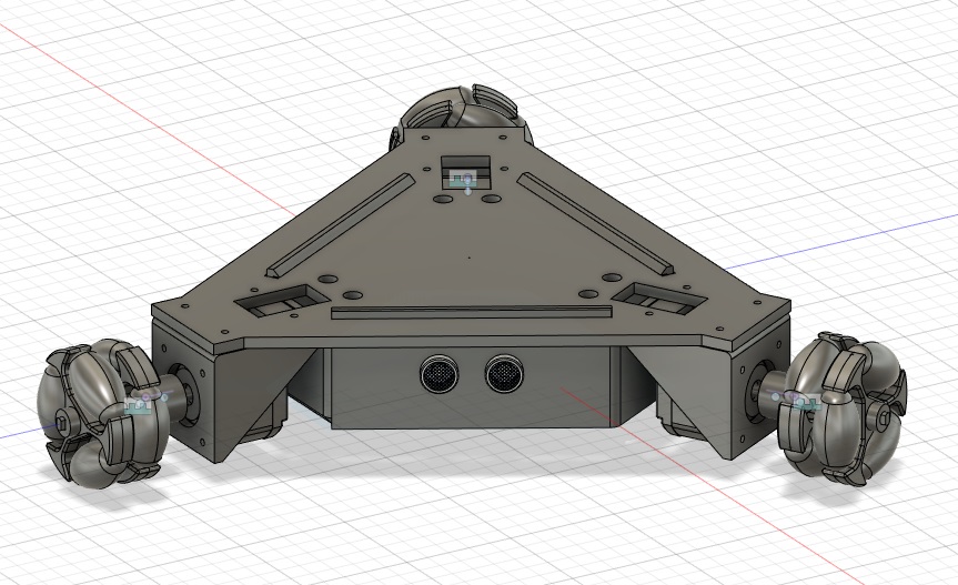
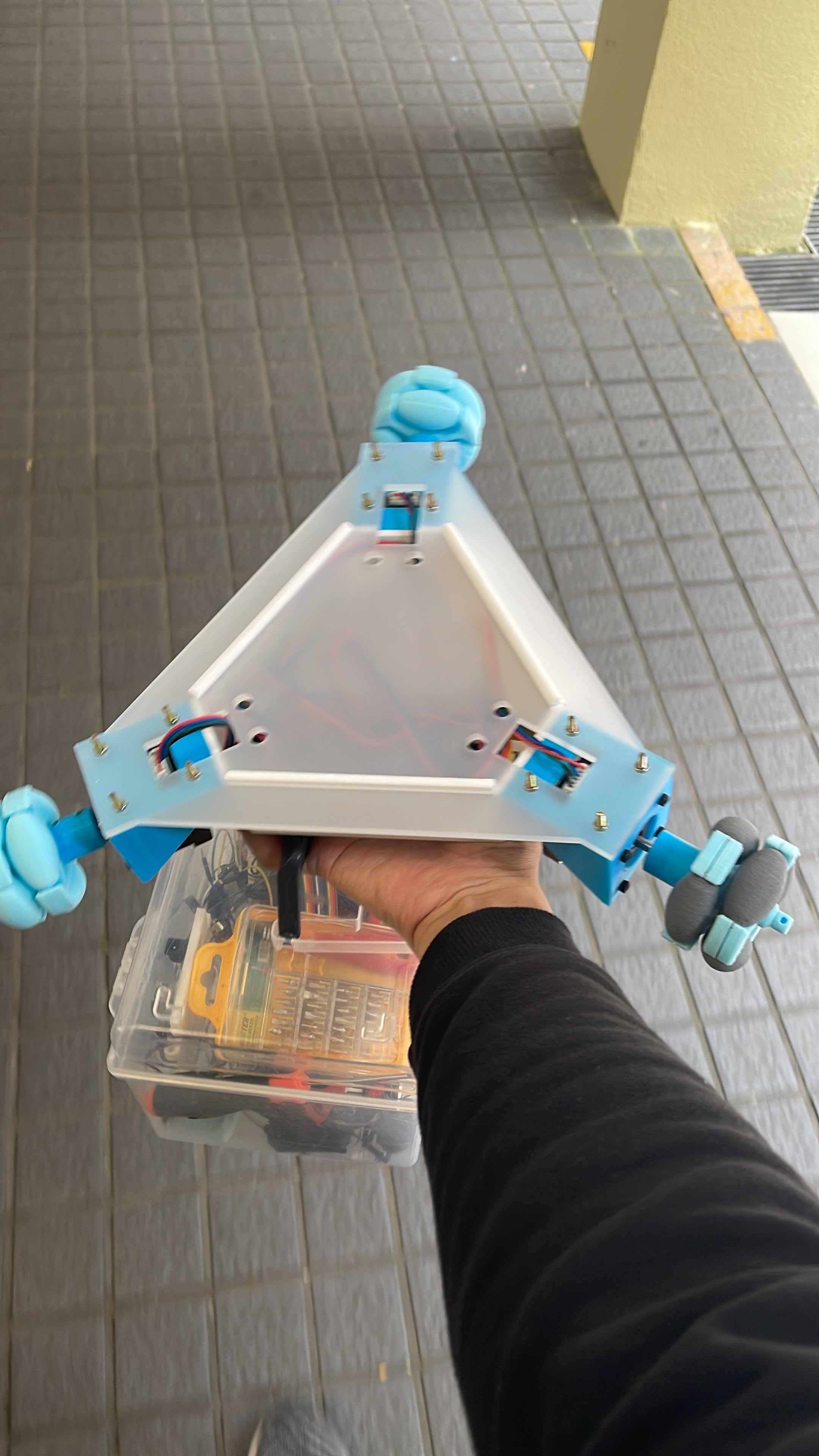
Putting everything together
Finally, I assembled everything together. I must say, the joy of seeing everything coming together has really overwhelmed me that day, as I held my own creation in my own hands, thinking back when all these were fuzzy concepts, until today where it is physically in my hands, was truly remarkable!
Files
- chassis step