10. Molding and casting
This week I tried to learn the fundamentals of molding and casting
Overview
- Review the safety datasheet of molding and casting materials
- Design a mold around the stock and tooling that will be used
- Mill the design: rough cut + 3-axis finish cut (2 or 3 part mold?)
- Cast parts
Reviewing safety datasheet
View the group assignment here
We will be milling on Bluefoam, which should be relatively safe, and easy to tidy up after milling. We need to keep the vaccuum ready, as it might generate a lot of bluefoam “chips”.
The 2 main materials that were shown to us were the OOMOO 30 for silicone casting and the Easyflo 90 for resin casting.
To check the safety of the material, we need to look up the Material Safety Datasheet (MSDS).
- OOMOO 30: https://www.sculpt.com/2017/Tech/MsdsTechSheets/MSDS_OOMOO_Series.pdf
- EasyFlow 90 https://polytek.com/content/pdf/SDS/EZF90B-21.pdf
Some key parameters were:
- Mix ratio by volume: The two parts might not have the same density, therefore if we were mixing by measuring volume, we follow this number.
- Mix ratio by weight: The two parts might not have the same density, therefore if we were mixing by measuring with a weighing scale, we should follow this number.
- Pot life: The time we get to work with (mix + pour into mold + any processing required) the material after mixing before it starts to cure.
- Cure time: Curing is defined as a chemical reaction to transition between liquid to solid state. Cure time is the time for material to be cured and ready to be handle/post-processed.
OOMOO 30
https://www.smooth-on.com/products/oomoo-30/
| Details | Quantity |
|---|---|
| Mix Ratio By Volume | 1A:1B |
| Mix Ratio By Weight | 100A:130B |
| Pot Life | 30 minutes |
| Cure Time | 6 hours |
| Color | Lavender |
EasyFlo 90
https://polytek.com/products/easyflo-90-liquid-plastic
| Details | Quantity |
|---|---|
| Mix Ratio By Volume | 1A:1B |
| Mix Ratio By Weight | 100A:90B |
| Pot Life | 5 minutes |
| Cure Time | 1-2 hours |
| Color | White, slight tint of yellow |
Beginning
Our instructor Steven gave us a quick tour on how to use the same CNC machine, the StepCraft, to do 3-axis milling.
This is a picture of the result of demo.
There are 3 types of toolpaths, namely
- 2D toolpath: cuts in X and Y direction
- 2.5D toolpath: cuts in X, Y and Z directions, but only 2 directions at a time
- 3D toolpath: cuts in X, Y and Z directions, and possibly all 3 directions at any time
For this assignment, we need to make designs that utilize 3D toolpath. To mill the parts, we need to generate the toolpath from Fusion360.
Design
Initially, I wanted to make a controller, similar to how this student that was shown in class did. But it doesn’t fufil 3-axis machining requirement. Therefore, I had to revise my plan.
I decided to make an Oloid, which was briefly mentioned in our Thursday reviews.
Oloid are three-dimensional curved geometric objects. I tried to design one based on the wire diagram that was shown on wikipedia.
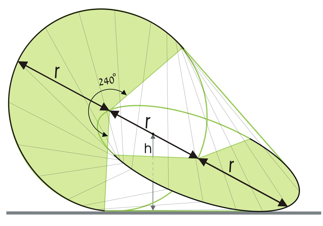
Initial Design
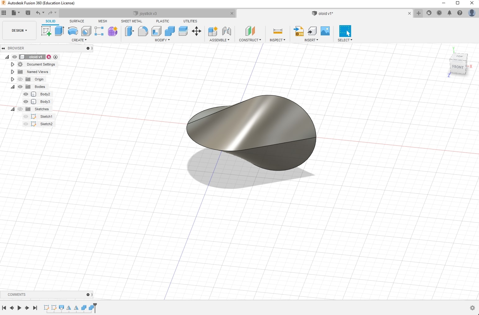
To start, I drew one circle, then drew a line from the center of the circle with length same as the diameter of the circle, then drew a tangent line from the circle to the end of the line. I did this for both XY and XZ planes. Next, I tried different operations, but felt that Loft is the correct operation to transition between 2 sketches smoothly. The result is a quarter of an oloid, and we mirror twice to generate the entire structure.
Here is the result:
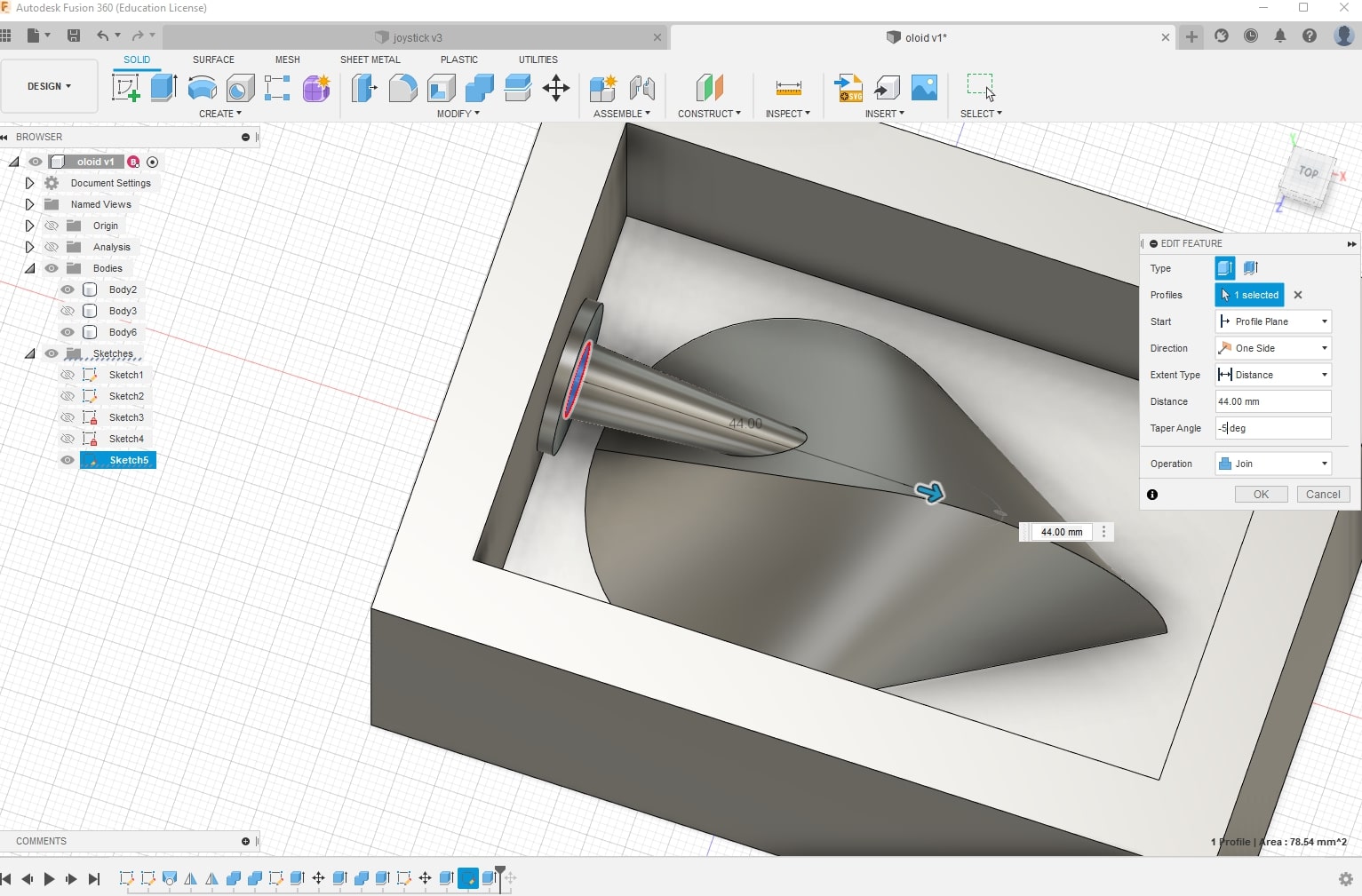
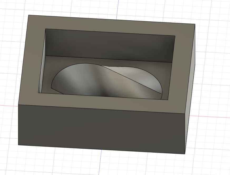
I wanted the design to be eventually casted to resin. Working backwards, that means my silicon cast would need to be in negative space, and the milling of bluefoam would be in positive space. I then made a 110mm _ 80mm _ 40mm box which represents the bluefoam’s width, height and depth, and placed a half of the oloid roughly at the center of the box.
From here, I had 2 options:
- make a silicone mold and cast 2 halves of oloid and glue them together
- make a two part mold and lock the two parts together and cast the oloid directly
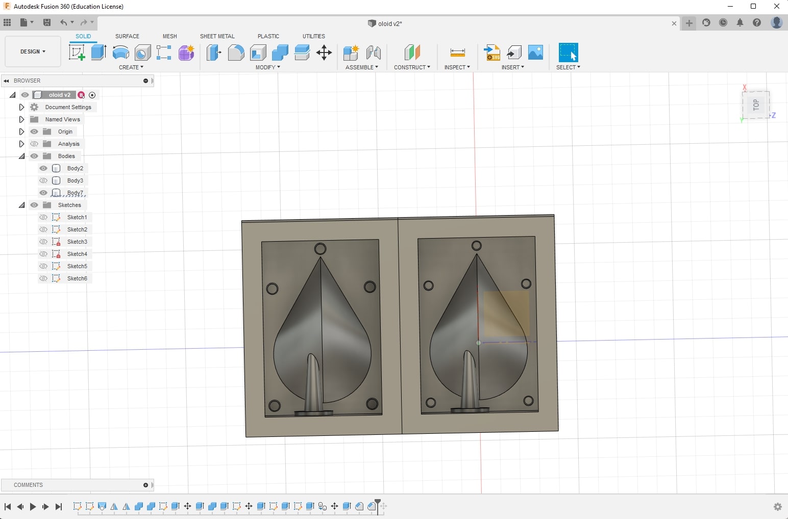
I wanted to try making this a two part mold, so I proceeded to make modifications:
- Add an opening to allow resin to flow into the mold. (the “entry” is negative space on silicone mold, which is positive space on design files)
- Add keys to help with locking the two silicone parts.
Revision
There were some very important design flaws, that I did not notice until Steven mentions it to me.
- Spruce should be as near to the top of the cast. The top is defined as where we start to pour into the mold.
- The spruce isn’t able to be machined as there is stuff to be milled underneath the spruce (higher than 3-axis machining required)
- Suggested to move away from key and instead try nesting all-round.
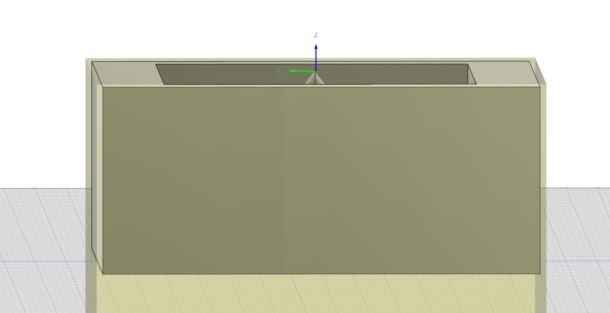
However, as I am running short of time, Steven suggested that I do a one-part mold first to get familiar with the process of molding and casting, and improve it as time goes on.
Therefore, I removed the spruce and keys, and decided to cast twice and later glue the two parts of the oloid together.
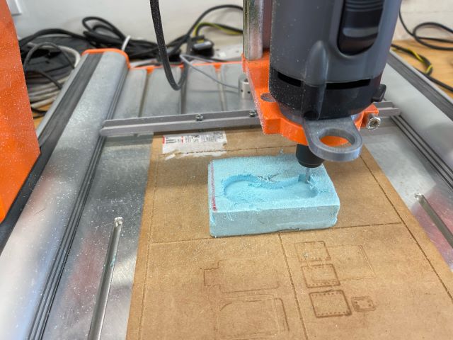
Milling the Bluefoam
Finally, I was able to mill the cast. We decided to use the Stepcraft 420 as we are already familiar with the machine (which was the one I drilled a hole through the PCB…).
To generate the gCode, doing it from Fusion360 is very convenient
- Preparation
- Generate Toolpath
- Save postprocess
- Check gCode
Prepare
- Go to Manufacturing
- Click “New Setup”. The key thing to do here is to check the Work Coordinate System (WCS). Check the orientation and make sure the z axis points to the top. - To do this, select either
Z axis/plane & X axisorZ axis/plane & Y axis. I selected the former. - Select the where the origin should be. This also dictates how we should zero the x,y,z axes on the mill. As we are going to zero it on the surface of the bluefoam, set it on the center of the top of the material and it should be fine - Check the second tab, where we look at the stock details.
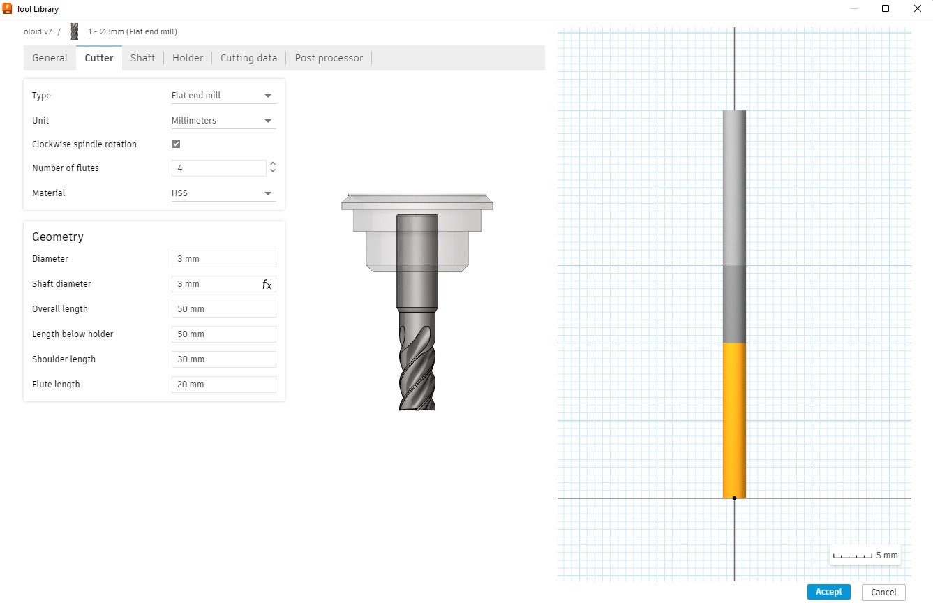
- Create a new Tool from Manage > Tool Library.
- The key parameters are found at the Cutter section. Here, we need to check the mill type, unit, flutes, tool diameter, shaft diameter, shoulder length and flute length(cutting edge).
- Set those according to the tool we’ll use. Note the tool diameter, shoulder length, flute length and flutes are crucial in generating correct gCode.
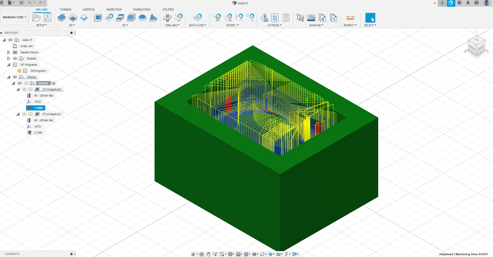
Generate toolpaths
Now we are ready to generate toolpath. To do this, select one of the many clearing methods. However, the simpler one is to use adaptive clearing.
After clicking on adaptive clearing, this is what we need to check:
- Select the tool, and disable coolant
- Set spindle speed to roughly 10000rpm. This is dependent on our tools
- Check the Cutting Feedrate, ensure that the Feed per Tooth is around 0.0375mm
- For rough cut, check to make sure that rest machining is not selected.
- Select the machining boundary
- For rough cut, go to passes, check that fine stepdown is 0.1 units of maximum rough stepdown (eg rough stepdown is 6mm, so fine stepdown is 0.6mm)
- For fine cut, go to passes, reduce the fine stepdown to the desired resolution (eg, 0.1mm)
Then click ok and it should generate the toolpath. Note: I made a mistake when generating this toolpath, this image is left in as part of documentation
(Optional) Simulation
In Fusion360, click on Simulation tab. Although it may not run exactly displayed in the simulation, it acts as an initial check to ensure no obvious stuff goes wrong.
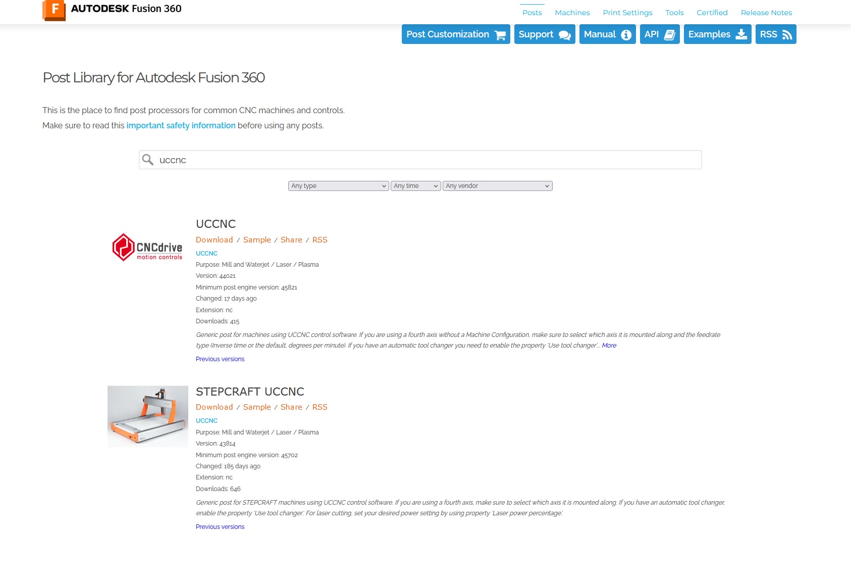
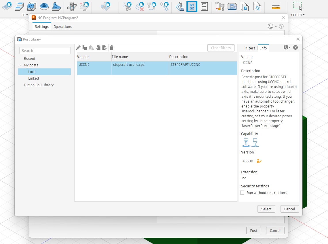
Save toolpath
Finally, when everything seems ok, click on PostProcess, import Stepcraft uccnc download from fusion360 CAM and download the .nc file.
Check gCode
upload to NCViewer to see if it cuts as we intend it to.
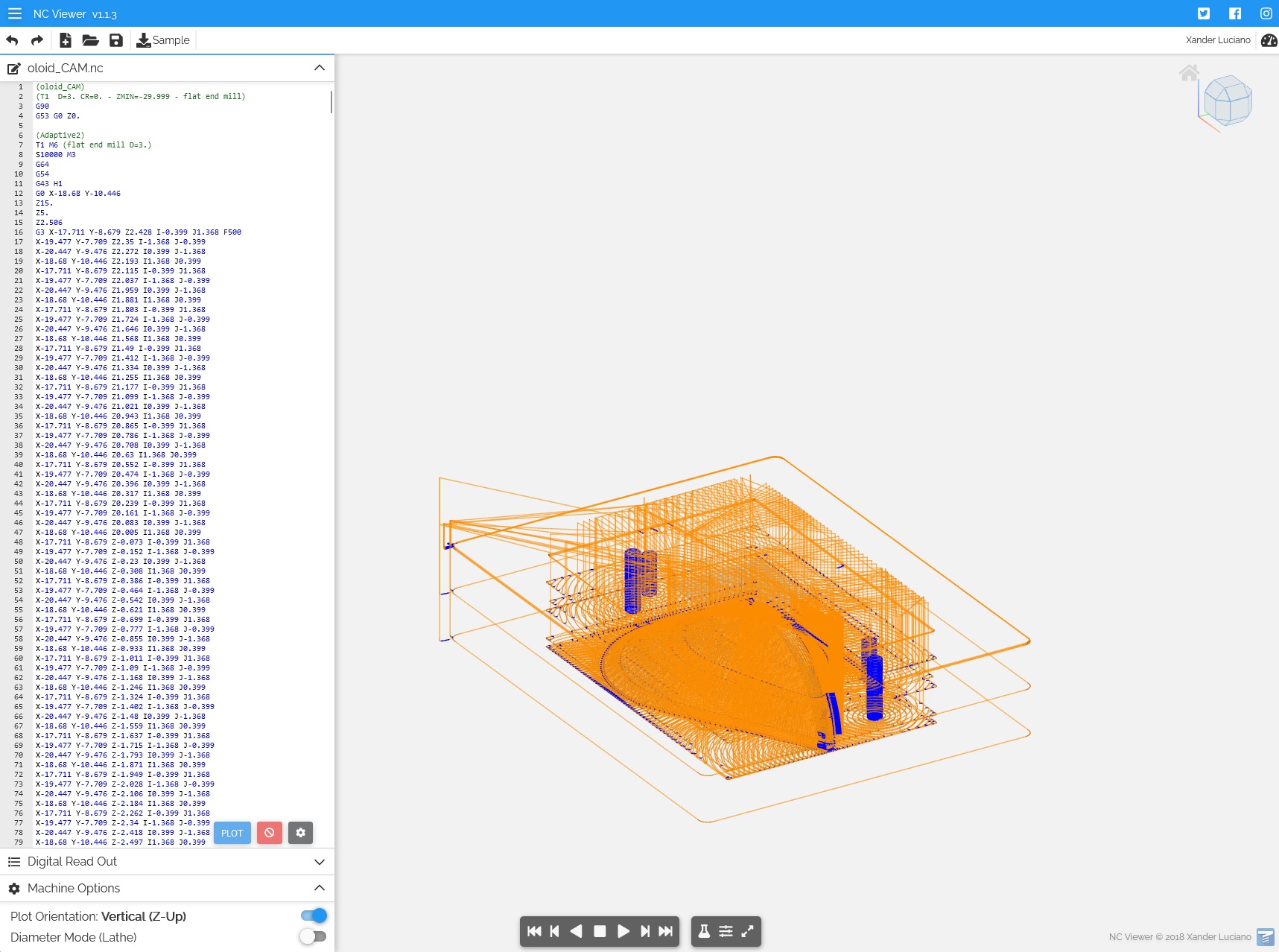
After verifying, everything is good to go!
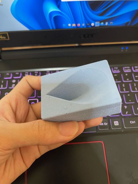
Learning points
- Give more length to the shoulder. I almost wrongly estimate the required height. If i had pushed the shoulder any closer into the collet, it may have collided with the inner sides of the stock
- Check to make sure there are no “extra cuts”. In fact, there were obvious red flags
- When generating toolpath, I believe I didn’t select a machine boundary when doing the fine cut. I did not notice it for some reason. This caused me to cut into the sacrificial wood pretty deep.
- Generating toolpaths in Fusion has a lot of flexibility due to needing to support different machines. It is barebones, but configurations were not easy to find. Need to use it a couple of times before getting used to generating toolpaths on Fusion360.
- I did not account for silicon to be above the oloid, and made depth of the hole the same as height of the half oloid, 20mm. To do a quick fix, an acrylic box needed to be made to house the cut stock. With Steven’s help, we laser cut the sides and hotglued them to a bottom piece of acrylic. This should circumvent the need to redesign and recut.
- It is better to fix this at the design phase, as this step makes the process unnecessarily complicated.
- The fix is to decrease the height of the oloid rather than to make the depression deeper. Technically I could do that as well, but the stock is an inch thick (25.4 mm), having around 2-3mm at the top and bottom is a little bit dangerous.
- Always measure thickness of stock before using it! There were some stocks that have been compressed to 24mm, and that could have been catastrophic if we needed the measurements to be very exact!
- Suggested to reduce oloid size to 17mm, so that we have around 8.5mm to be distributed to top and bottom
Casting
First Cast: Silicone
I made a first cast, to make the mold required to cast an oloid.
We used OOMOO 30.
Before using it, mix well. I used a stick to stir the oomoo evenly in the container.
Our lab did not have rice to estimate the volume required, which would have been much easier. That being said, I poured Part A, which was less viscous but take up more volume first. Roughly, I saw that the volume is slightly higher than the depth of the stock. In terms of volume, I needed to pour the same volume of Part B into a separate cup, and then mix the two together.
| Type | Amount |
|---|---|
| Part A | 155g |
| Part B | 195g |
It was not easy getting the last few grams accurate due to viscosity of the mold.
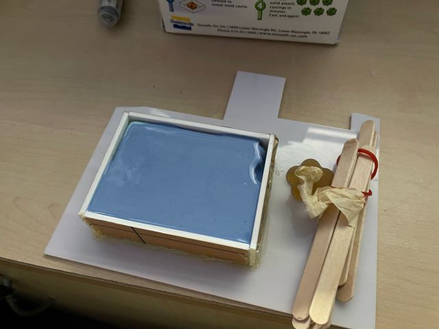
Wait overnight for result
Second Cast: Resin
For second cast, we cast from the first cast using resin.
We used EasyFlo 90 Resin for the second cast. The required ratio is around 100:90 in weight, 1:1 in volume.
| Type | Amount |
|---|---|
| Part A | 15.2g |
| Part B | 13.6g |
I did a small test to check if the Resin is still ok to be used
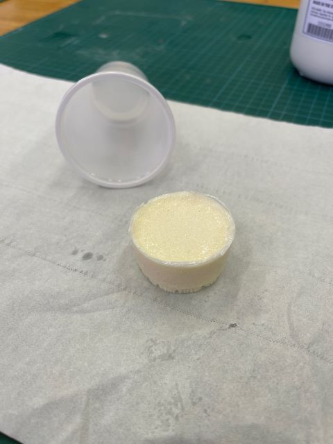
The coupon had a bit more yellow tint, but is otherwise in good quality.
I repeated a mixture and it was initially clear:
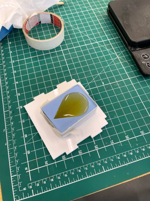
After a while it turned a milky white:
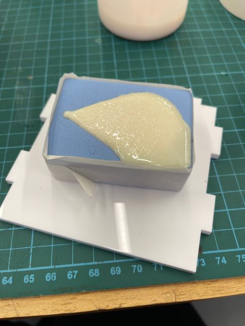
This was the result after it has fully cured
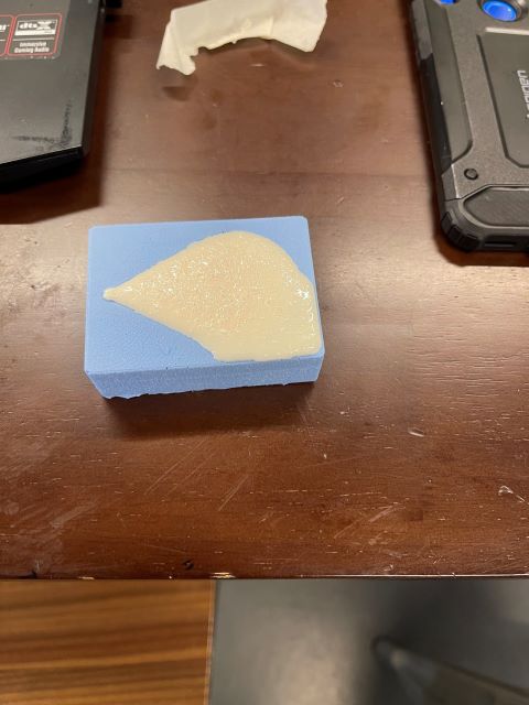
The cast was repeated to get two halves, of which they will be glued together.
Post processing
I tried to pour in as less resin as possible. However, it still overflowed by a little bit, meaning that I have to sand down the parts before joining the two halves together.
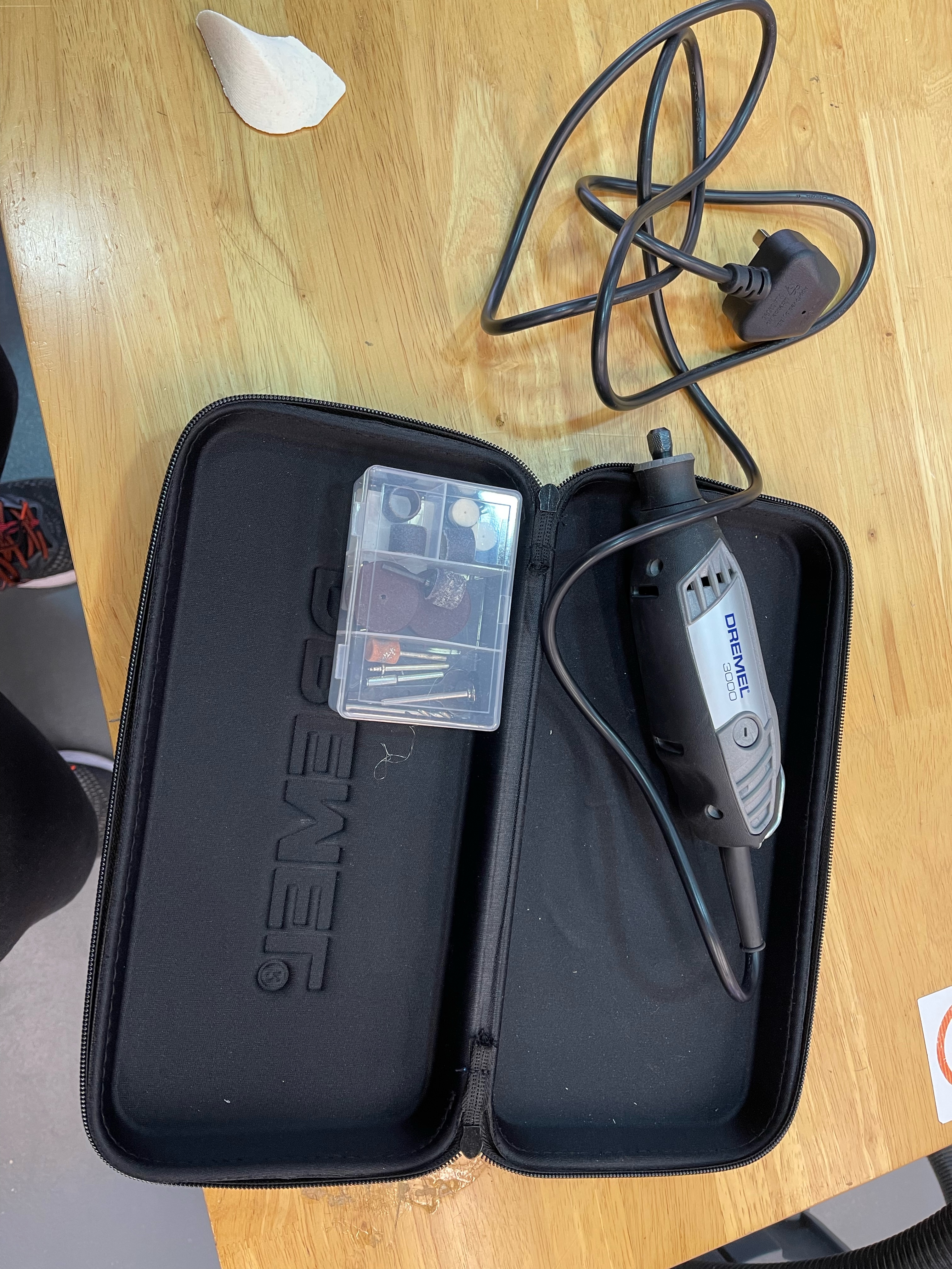
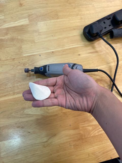
I first used a dremel to grind off larger chunks around the model.
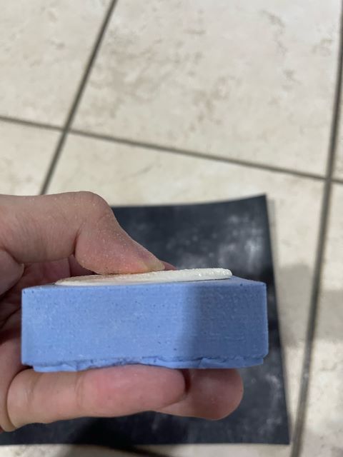
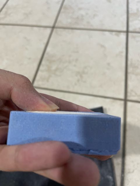
Then, I used a file as well as rough sand paper to sand off the excess bottom surface. I used the original silicone mould as a reference for how much material I should remove.
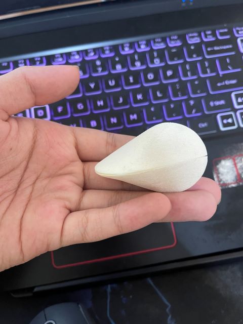
Lastly, I glued the two parts together with superglue and my product is complete!
Results