Integration
What constitutes this?
- Programming robot to move
- Write application to control the robot from my computer
- Final test run
Final test run
After I fixed some minor bugs and resolved as much issues as I could, this was the final result!
Problem: wheels skid inconsistently
After a few tries, I noted that the robot with the same code may/may not move to the same location. This is because of the material used to 3D print the wheels. Althought TPU provides better traction than PLA, it is not nearly enough to provide a consistent rotation along the floor. This made a lot of my calculations and testings nearly impossible.
The consequence of this is the lack of accuracy despite using steppers! That’s not what we want… Perhaps there is a way to fix this?
Idea 1: Use actual rubbers to cover the wheels
This is currently not feasible, as “rubber like materials” is not easily found for a wheel of this size. I would need to redesign quite a few things before it would work as per intended.
Idea 2: Add weight to simulate for calculation
I could do this if I become more confident with the entire system. The only thing to worry is the acrylic sheet breaking. But given the size, I don’t see it happening anytime soon.
Idea 3: Put some tape on, then pull the tape out, leaving some sticky residual
This idea originally came from Steven as a means to get more traction against the ground. I think this is the fastest fix, if I didn’t care about the wheels being sticky…
I’ve decided to postpone this issue to the next spiral, as I did not expect TPU to not solve this problem completely.
What about powering the robot?
To prioritize and deprioritize stuff, I think that having the power system deprioritized was acceptable. The connections to the LiPo were made available, but I was too scared to make the connections directly. I instead powered the robot with a wall plug, which I think was acceptable, as there was no need to identify how long the robot can run in this spiral.
You can read more what I have read on power systems at Appendix B, I decided to not include it in the documentation because that is a whole other rabbit hole to go into.
Moving the robot
From the testing of steppers, we know that the robot is able to rotate it’s wheels, but how should we coordinate the movement? This requires some calculation of what speeds the motor should be rotating at.
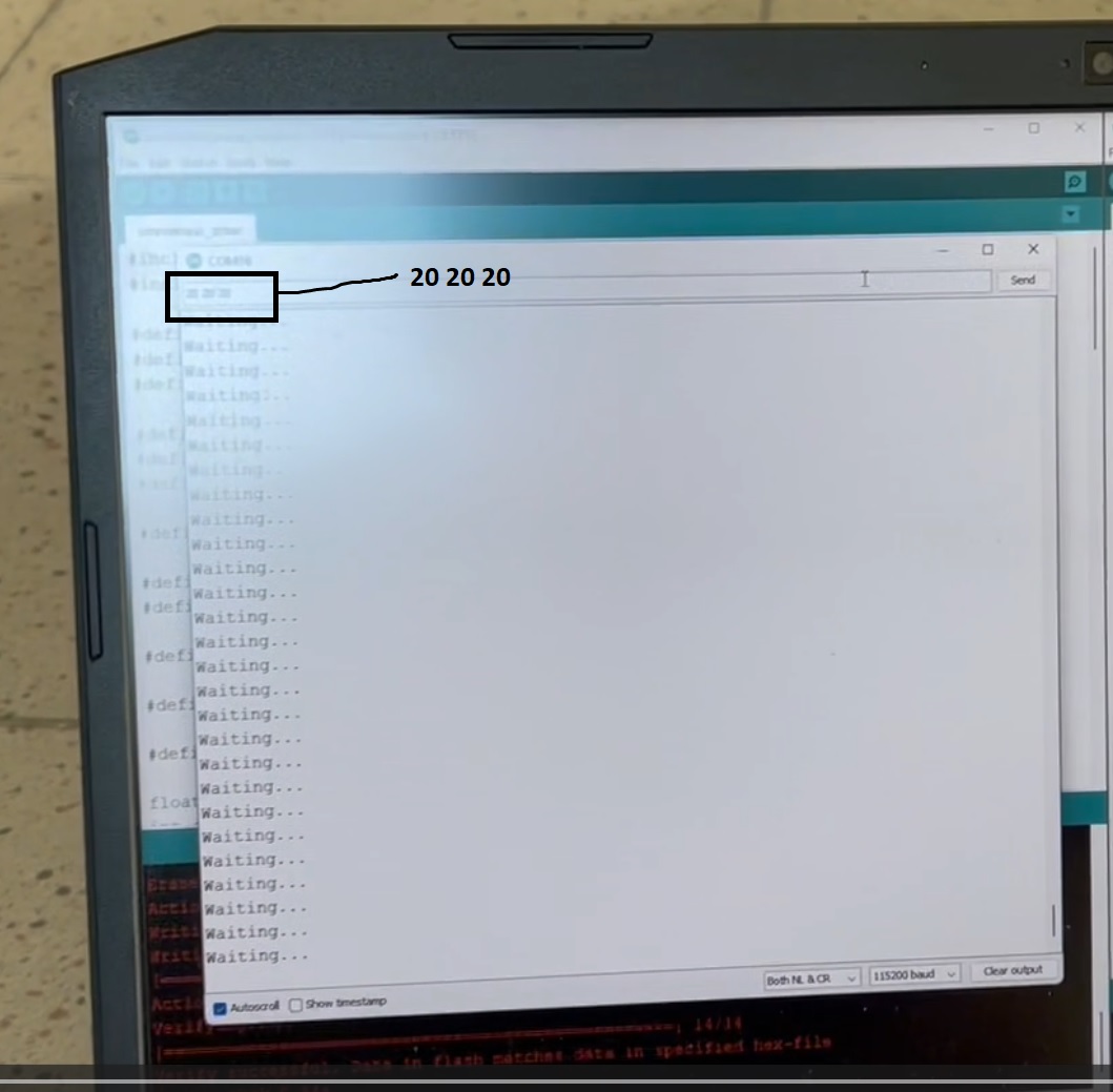
After deliberating this for a while, I decided that it is best the calculations be done on my computer, and velocities for each wheel transmitted to the robot. I try to send expected values (speeds) via Hardware Serial to the microcontroller controlling the drivers.
I find that the video taken was a bit blurry.
- Initially, I put in values
20 20 20to show that it rotates in place by a little bit. - Next, I put in values
50 50 50to show that it rotates in place slightly more.
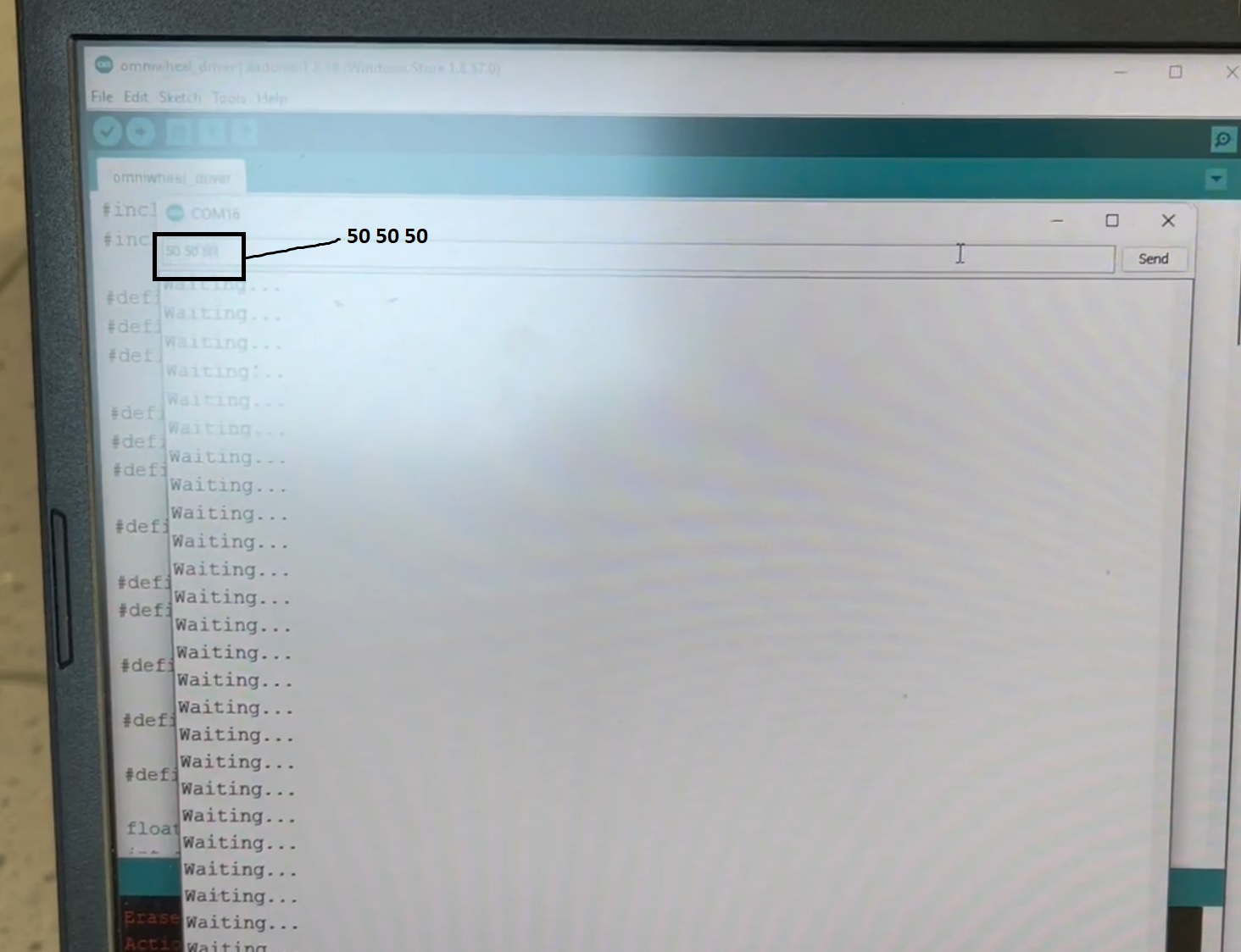
The robot is now able to move! Albeit everything not packaged yet.
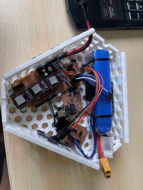
Packaging everything together
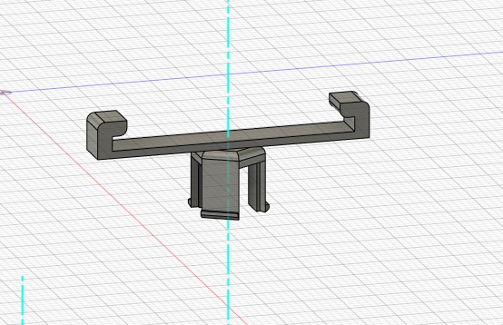
Thanks to Louis’ recommendation from chassis, It was quite easy for me to make mounting brackets for each of the PCBs. I just made clips to clip onto the base of the hexagonal patterns
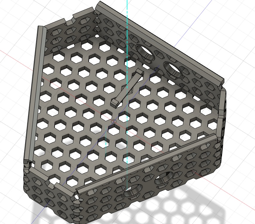
Lastly, I painstakenly placed all the components in the chassis and it looks something like this. Note that when I was doing the packaging, I still left space for the LiPo as I thought I had enough time to integrate it into the system. It is left in to show that by swaping the barrel jack with a LiPo Male Header, the robot should be able to work without issues.