3. Computer Aided design
This week I learn different tools to convert a mental image of my creation into a digital version.
2D Design
Raster
In rasters, images are represented as pixels, or 2D squares. In a sense, it is a more traditional way of looking at images. To gain a quick sense, we can easily view this when creating powerpoint slides, where sometimes our images seem to be of low quality, and very “pixelated”. There are tools online that can help improve the image quality by “upscaling” the image, such as waifu2x (Despite the otaku-esque name, it is quite useful!). The code is open-source and you can find it on their website (or here).
To do raster graphics, a built in application we have is MS Paint. It is however, somewhat basic, and lacks abilities that other rastering tools have. As such, a tool that was greatly recommended in this course was GIMP. The installation was straightforward, just download the windows installer .exe file from GIMP and run the installer.
I quickly made a simple new drawing to test GIMP out. I was pretty confident that I could do something similar in Paint.
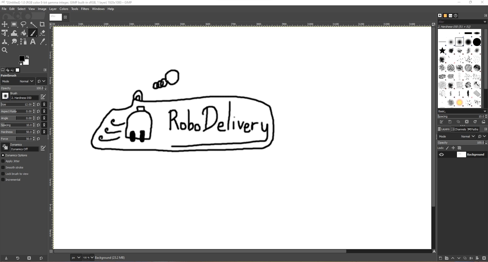
However, GIMP had Layers, which MS Paint did not have. This meant that I can save this work and apply different types of colors on a similar sketch without simply breaking it! With that in mind, I made 2 layers, one for the color of the car, and one for the background of the keychain.
When I applied colors, it stays on top of the keychain! Perhaps the proper way to do this is first have a sketch, then color, then finally draw hard lines to represent finalized lines. However, my intention was to draw the final outline, then add colors. So what I tried to do was move the layers around, and it should be fine right?
However, I did a mistake by drawing on the background layer, which I did not set as transparent! Ooops! I tried to cut the lines into another sketch, but the white background followed!
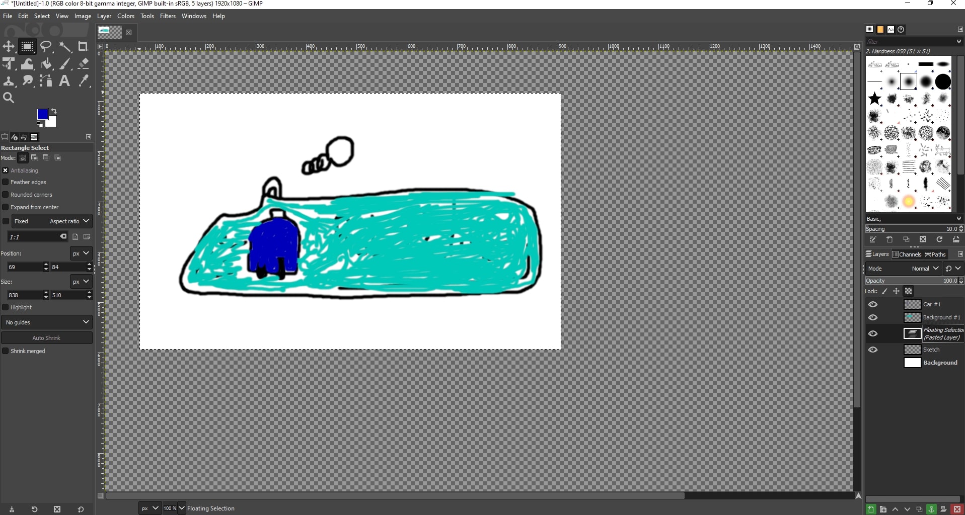
No matter what I did, I could not get the colors to appear behind my sketch while on top of the white color :’)
The only solution I could find is to retrace the lines on another sketch
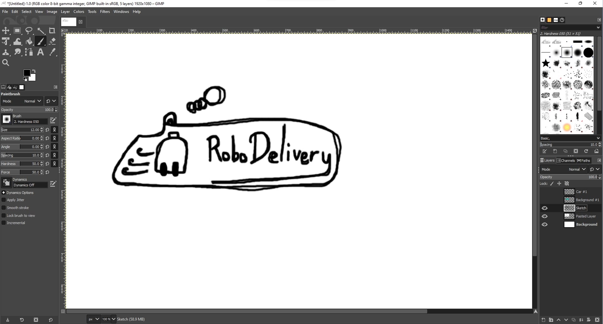
As currently I need to separate two drawings that should be in different layers from a single layer. After searching online, I only noticed that we can flatten 2 layers into 1, rather than doing the opposite.
Then, by moving the color layers around, I was able to show my quick sketch!
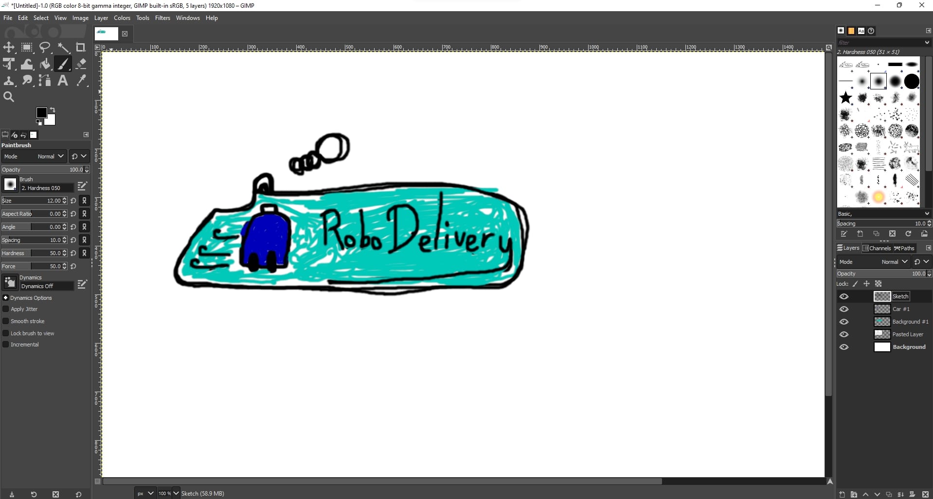
However, by zooming in, we can see that the “lines” are composed of many small 2D squares. If we had exported this image in say 320p, and set it as a background for our google slides, this is what we will see!
Vectors
Vectors to the rescue. Vector graphics store strokes instead of the images themselves. Some examples are Simple vector Graphics (or SVG for short). A popular program used to make vectors is Inkscape.
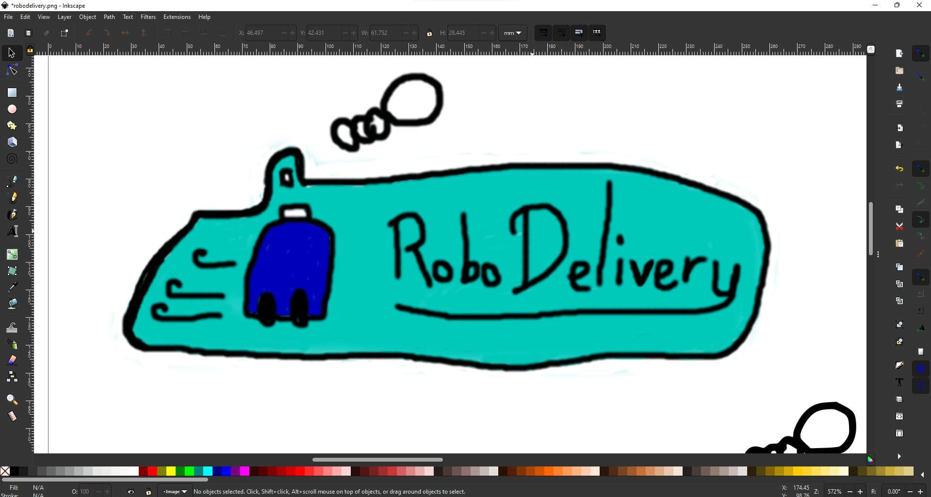
Our Instructor, Steven Chew, told us that Inkscape has good capability to vectorize PNGs, cheers!
To do that, go to Path > Trace Bitmap -> Click Apply
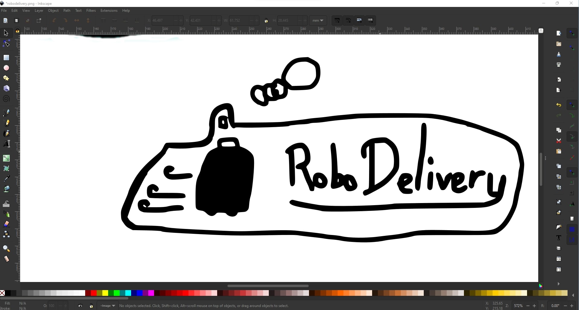
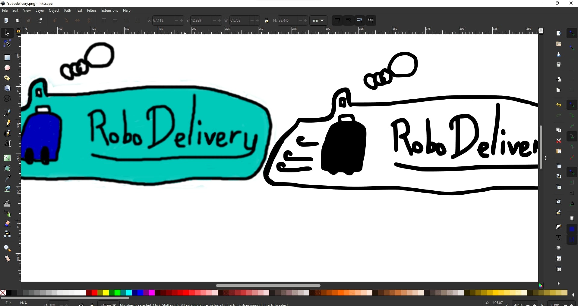
After doing that, I zoomed in to see the difference. Indeed, vectorized PNGs convert the PNG into line strokes, and no matter how much I zoom I cannot see any “pixels” in the vectorized PNG
3D Design
I wanted my final project to be a food delivery robot. As such, I want to start with the CAD of certain parts. The software I will be using is Fusion360.
Some of the basic/general concepts I used were as follows:
- To create a cuboid: Create a sketch, then draw a rectangle, add dimensions to the rectangle, extrude the rectangle to desired height
- To create a cylinder: Similar to cuboid, but use a circle instead of a rectangle
- To repeat shapes: We can use either circular pattern or mirror, these operations exist for both surfaces as well as bodies/components/objects.
- Circular pattern: Choose a shape, specify center of duplication, modify quantity. The shapes are equidistant from one another
- Mirror: Choose a shape, specify a line/plane of duplication. The shape is equidistant from the original
- Searching for tools: press
s, enter tool/command name - Offset planes: Useful when need to mirror components. There is a hotkey at the top, click on a face or a plane, specify a signed offset distance.
- Parametric design: Add User Parameter, modify d1, d2, etc to use the parameter added as per needed.
- Add joints: “Connect” 2 surfaces via a joint. The first surface selected will move towards the second surface. In this week I used mainly rigid joints and rotating joints (about an axis).
Other specific skills used in each component is documented in their respective section
As a proof of concept on how the delivery robot will work, I wanted to CAD 3 basic components
- Robot chassis
- Wheels
- Food storage
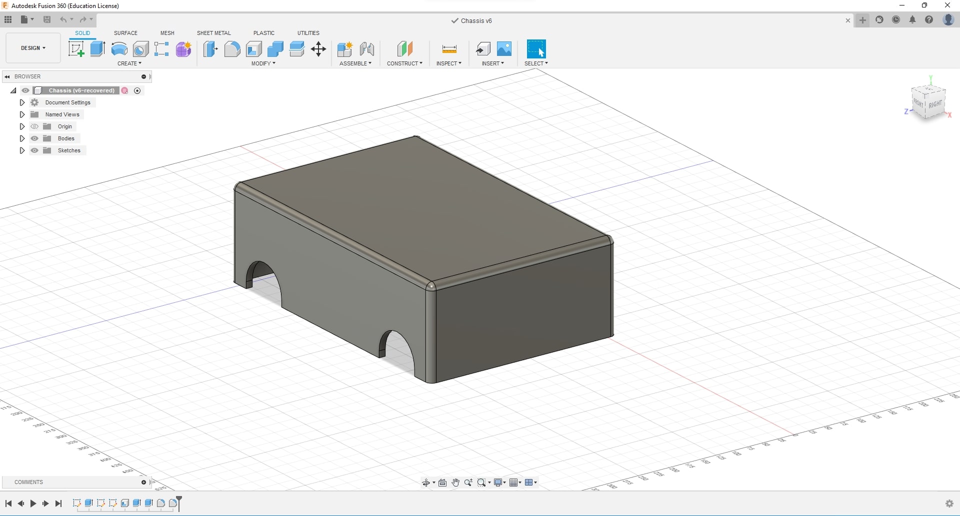
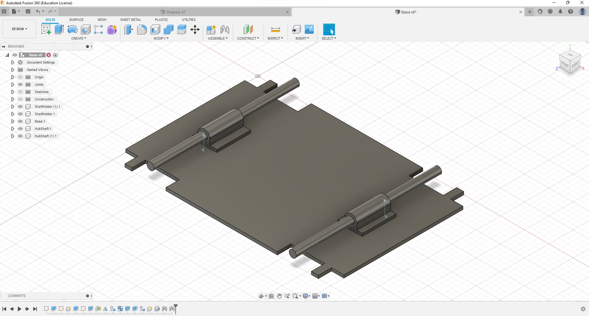
Robot Chassis
For the chassis, I decided to go with a simple cubic design, and have space for the electronics and power delivery systems.
To make it look a bit nicer, I added fillets around the chassis, and prepared some holes for the wheels. The chassis is also hollowed out using the shell command.
I created a simple base for now. I also added some shaft holders and a shaft to hold the wheel in place. This is for the sake of showing a proof of concept, and will be changed to motors for accurate control of wheel movements
Wheels
There are mainly two types of wheels, a normal wheel or an omnidirectional wheel. As I foresee this robot potentially navigating within tight spaces of offices, canteens etc, having omnidirectional wheels are beneficial. As such, I have decided to go with a mecanum wheel design for now.
I was debating on just taking a mecanum wheel online and crediting the author as I do not know how one is CADded, nor how one can make such complicated shapes. However, I think this is the perfect chance to step out of my comfort zone and learn something new. To start somewhere, I followed a video tutorial on Mecanum Wheel Design, and tried to understand the basic principles.
Essentially, the mecanum wheel is comprised of 4 components
- Wheel frame
- Center Hub
- Rollers
- Roller shafts
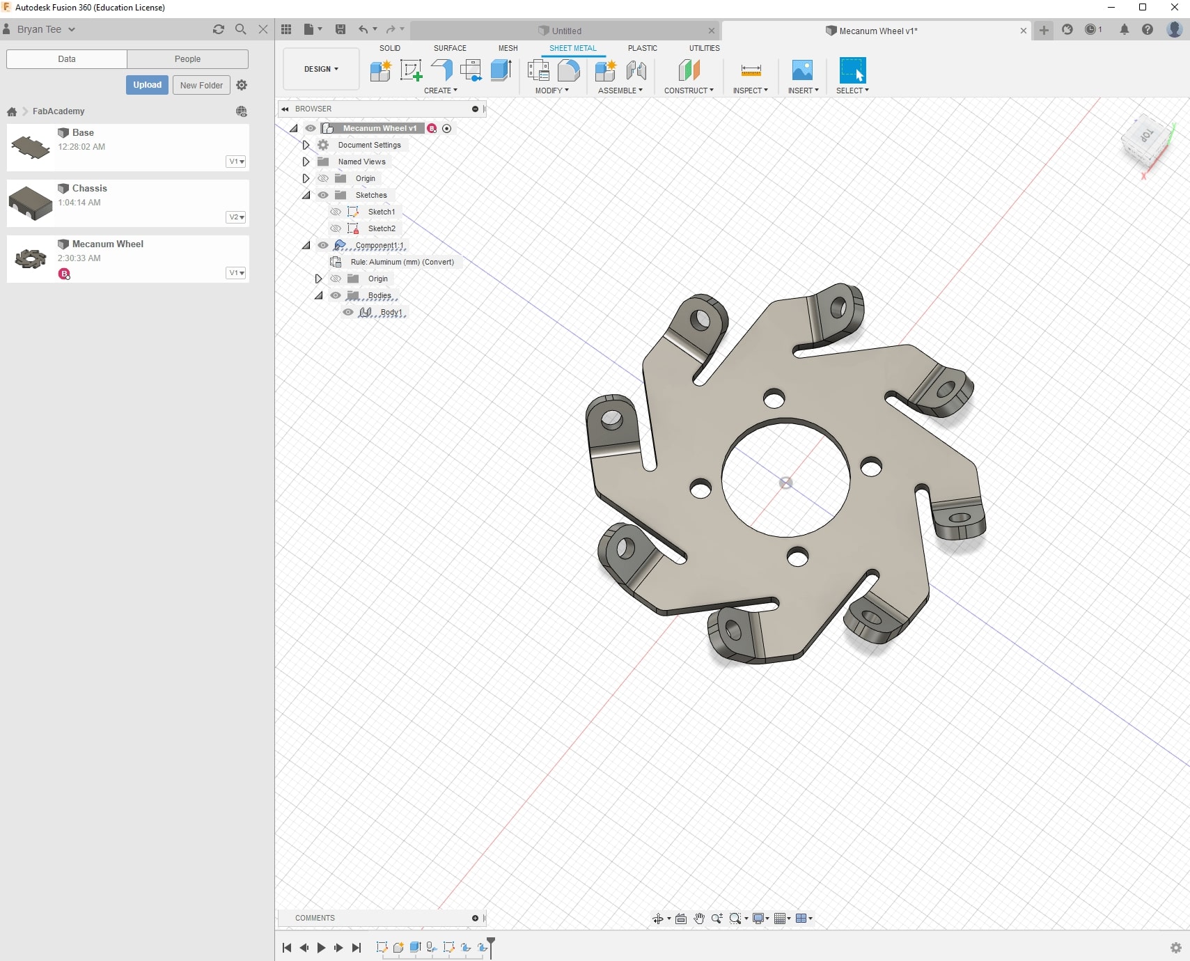
Wheel frame
Here, I learnt about the “Sheet Metal” functionality in Fusion360. I learnt that you can extrude a surface as not only a body, but a component, and turn component into a sheet metal component. That way, we can apply bends to the object!
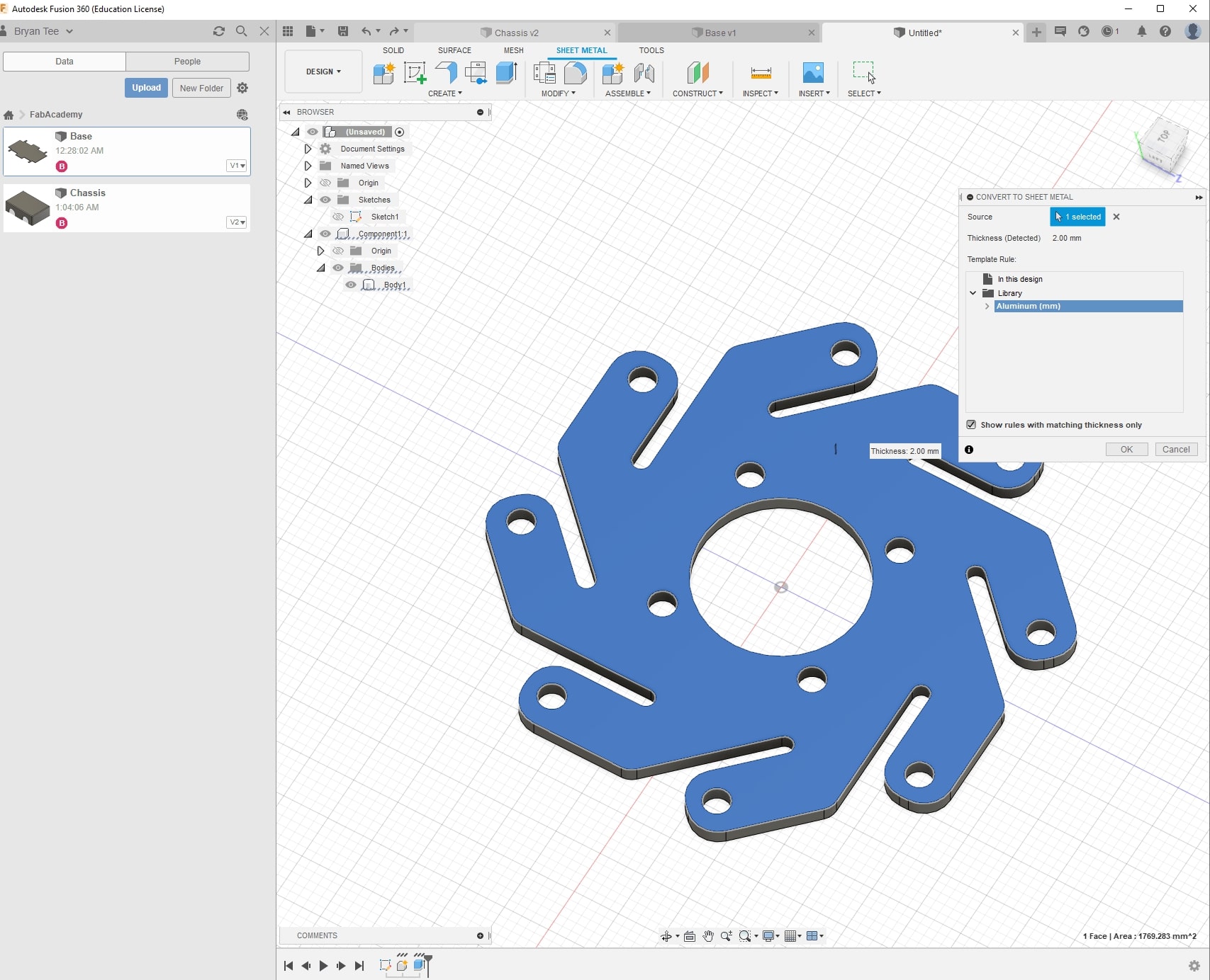
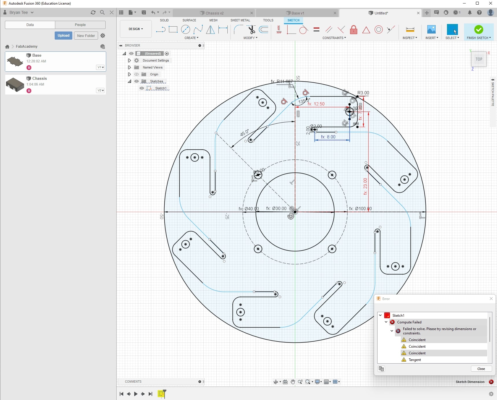
I attempted to apply parametric design on the frame so that I can freely increase the dimensions of the frame. However, I am facing some weird issues with constraints unable to be computed. Perhaps my approach was incorrect, but this isn’t critical to completing the assignment, and I will learn more about Parametric design in the following weeks. Perhaps I will simply notice my mistakes
Center Hub
The center Hub will act as an anchor for the wheel frames to attach to. The hub is relatively simple, so it’ll be shown alongside the next section
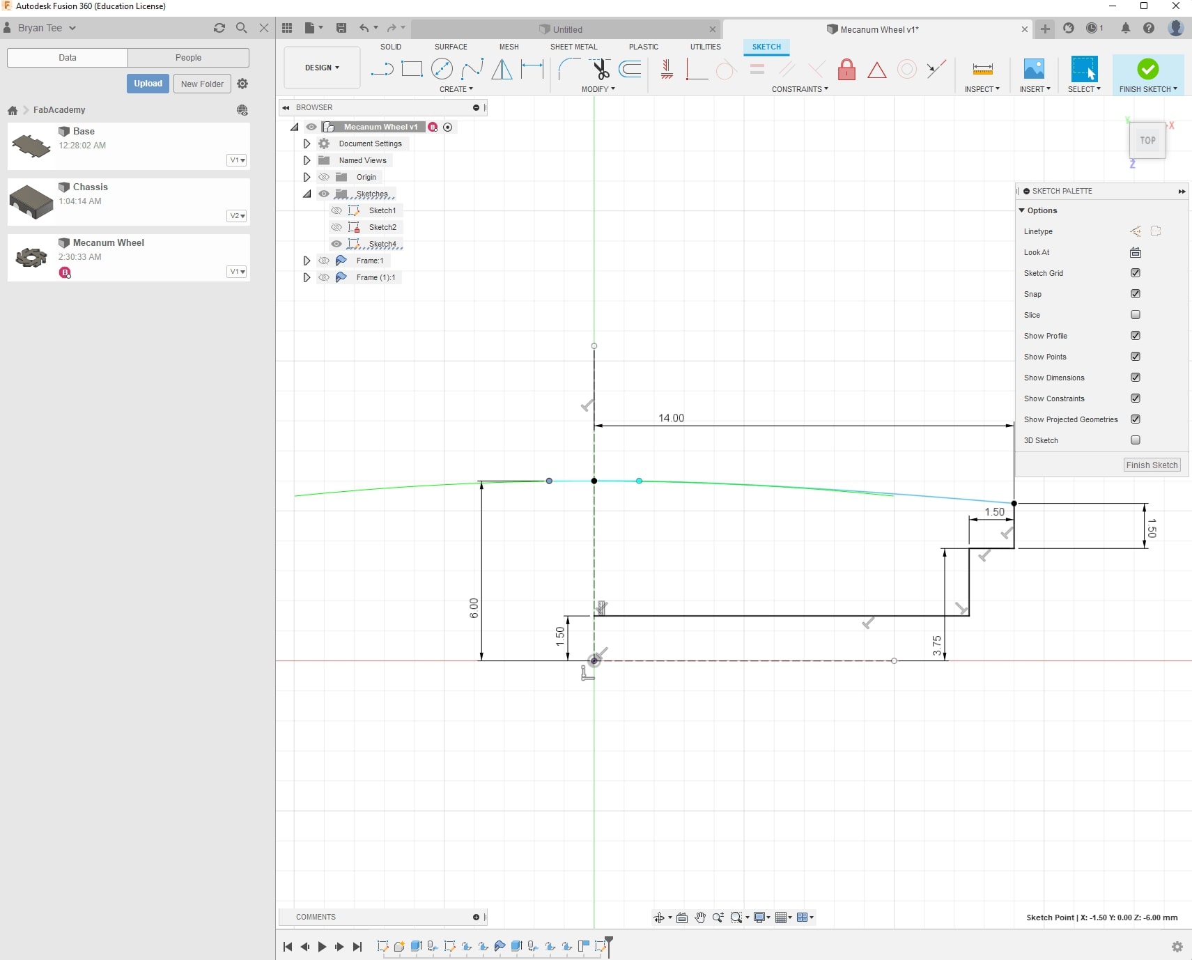
Rollers
One interesting I learnt is that the rollers are not perfect cylinders, but have the middle portion buldged out. This means a simple circle with the extrusion at the base will likely be problematic in generating that shape. As such, It is better to use a cross section of the wheel and do a revolve command on the created face.
Roller shafts
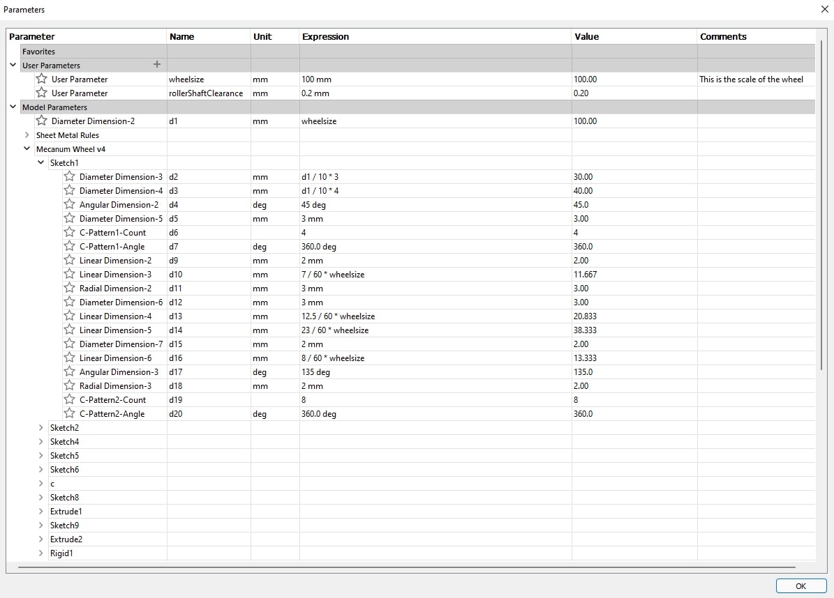
These shafts should naturally follow the size defined by the Hub and Rollers. As such, I decided to exercise some parametric design here :)
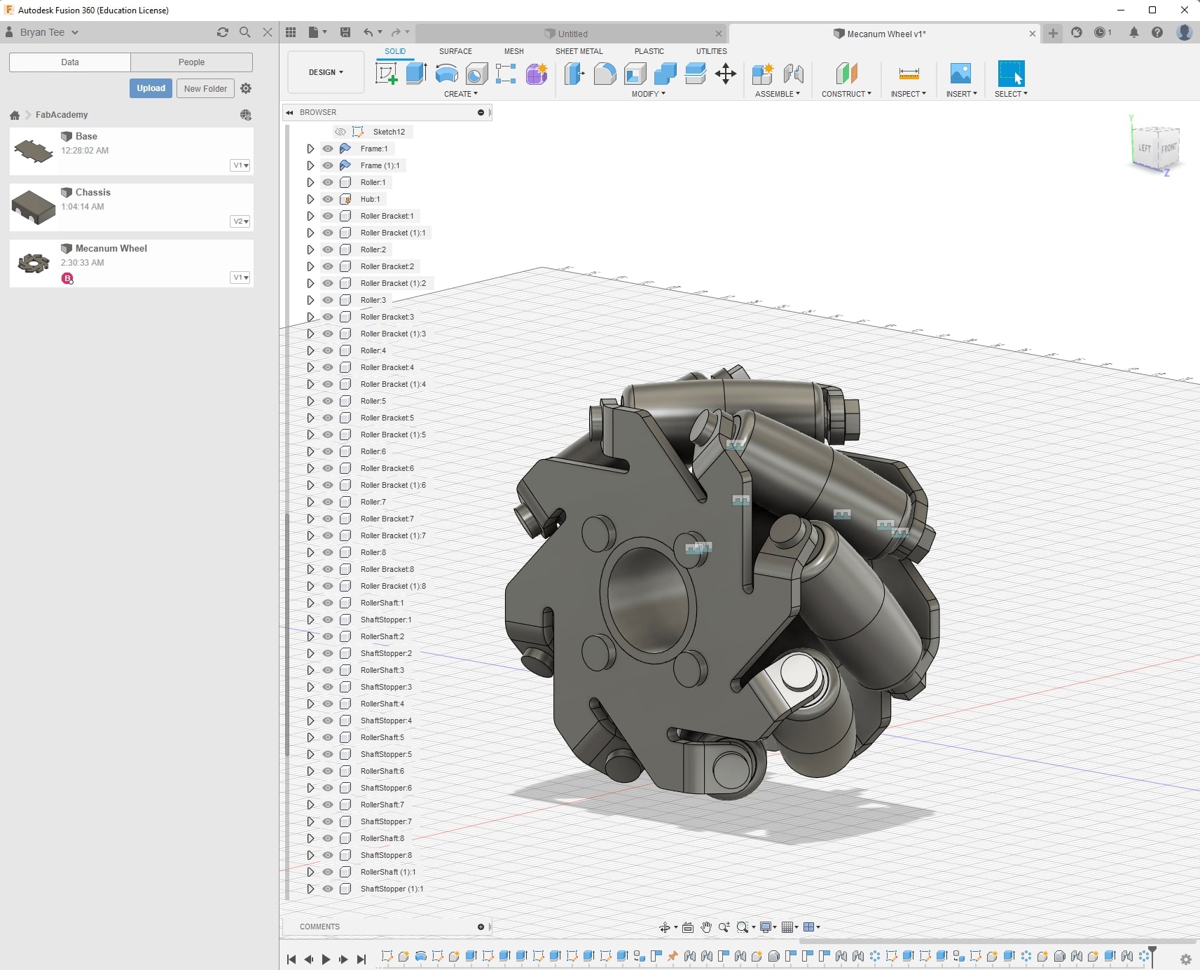
Connecting them together
I first focused on how to assemble one roller onto the metal frame and hub.
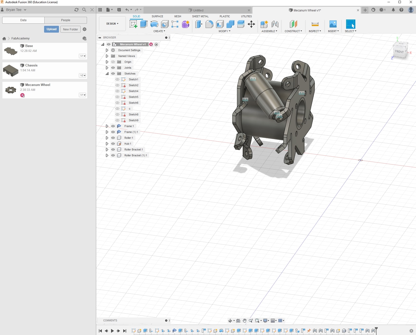
Then, I used the circular pattern function to repeat this assembly around the hub. This is the reccomended way to do this, as it would take too much time otherwise.
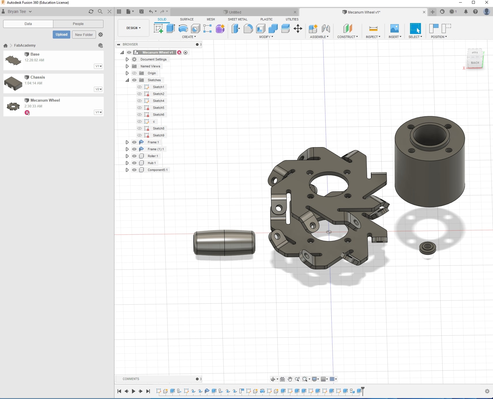
Exploded view
I wanted to make an exploded view as shown in the introduction of the video tutorial I followed above, but it wasn’t shown. As such, I had to do some googling on how to do that in Fusion360 (or other programs).
Again, Fusion360 is a powerful tool, and supports said exploded view. To do so, we need to first go to the animation tab. Fusion360 has a very useful auto-explode option.
However, if you noticed, it explodes all over the place, and sometimes the objects phase through each other. As such, I manually transform the pieces to my liking, and this is the result.
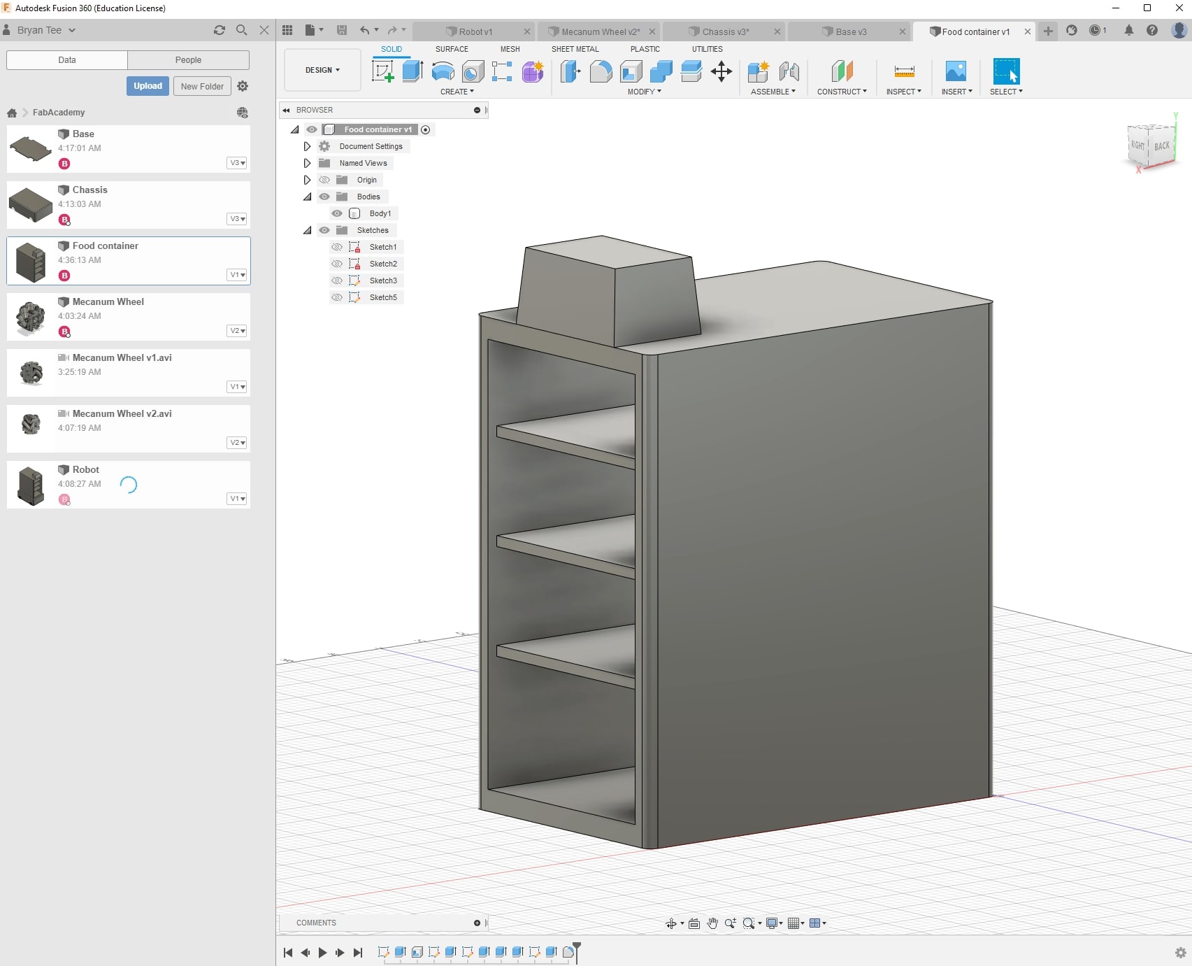
Food Storage
Currently, I am thinking of a simple latch mechanism, where people can either scan their ID cards or show a QR code to the robot to unlock the latch that leads to their packed food. I’m thinking of CADDing the food storage in detail next week, as part of Conputer Controlled Cutting Assignment. For now, a simpler version should suffice as a concept
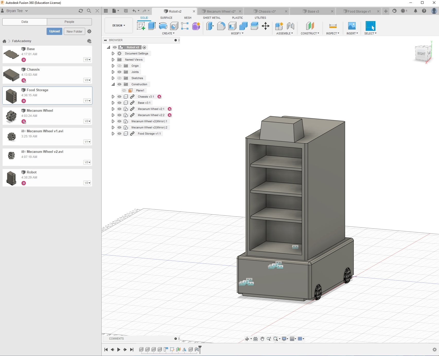
Final Product
As such, my initial concept that was a mere mental image has been converted into a digital design!
Render
After my robot has been built, I wanted to also try to render it in Blender. Again, installation is straightforward, as we just needed to go to blender.org to download the .msi installer.
In order to import the assembled model of my robot, I need to import them as STL files. After some deliberation, I figure that it might not be as beneficial at this point of time to learn the proper way to assemble my robot in Blender.
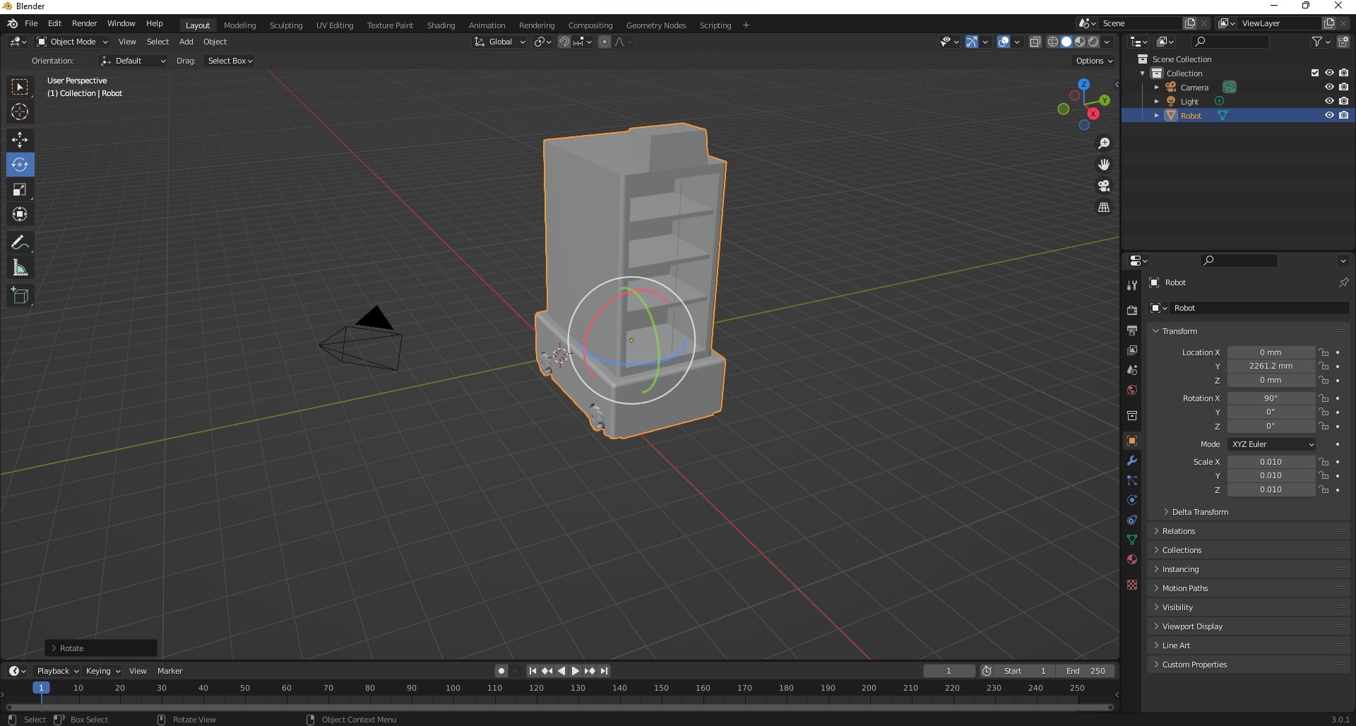
To have a quick view of how it will look like, we can navigate to the render tab, and do a real-time render view
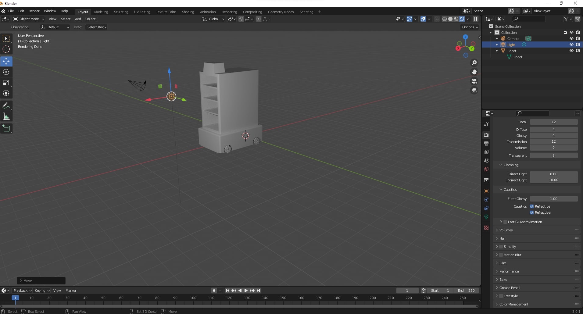
Initially, I wanted to see how a render would look like. I directly rendered a my vanilla robot in Blender, and found that it looks too basic.
I wondered why rendering wasn’t using my GPU more intensely, as my laptop had an RTX 3060 discrete graphics card. According to this article, there are apparently differences in rendering engines. For real time rendering, it needs to be optimized well. However, a more realistic rendering would require us to use a non-biased engine, such as cycles. The only downside is that it is grainy, as it takes time to compute the render results, and shows a partial render each time. Therefore, it is recommended to have a discrete graphics card, otherwise it will take way too long to fully render our image.
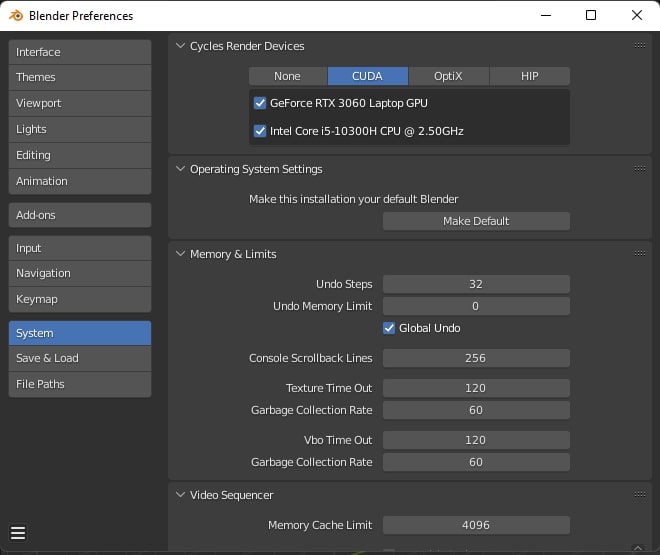
To enable GPU compute, ensure your GPU has its corresponding drivers detected. For NVidia graphics cards, ensure CUDA is available; although I do not own a Radeon or AMD card, at least ensure OpenGL (or some counterpart of CUDA) is available.
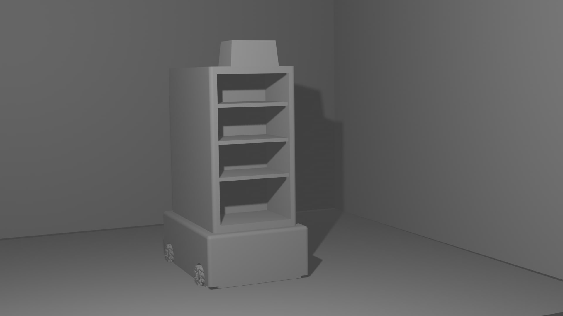
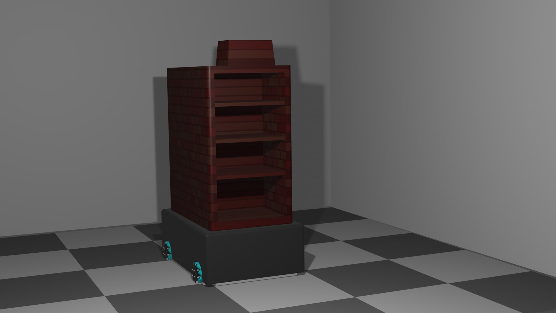
Here are the differences between Eevee and Cycles renders. Do note that Eevee took a few seconds, while Cycles took a few minutes to completely render (I was writing this section as Cycles was rendering, and it had just finished rendering with GPU compute)
 Rendered in Eevee
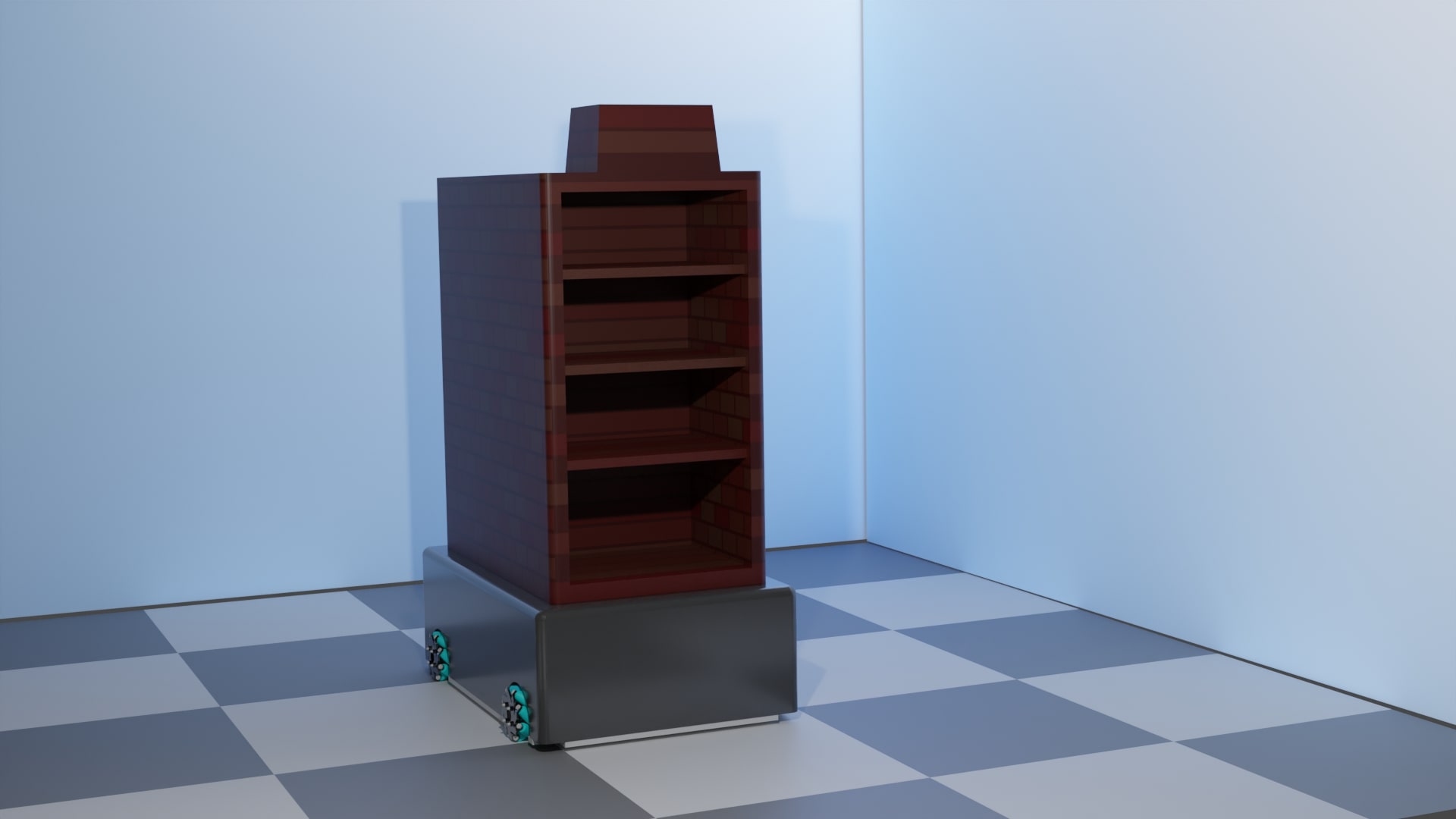 Rendered in Cycles
Original Design Files
- Raster image: robodelivery.xcf
- Vector image: robodelivery.svg
- 3D models:
- Chassis: Chassis.f3d
- Mecanum wheel: Mecanum wheel.f3d
- Base: Base.f3d
- Food Storage: Food Storage.f3d
- Complete Assembly: Robot.f3d
- Render:
- Imported: Robot.stl
- Blender file: simple_robot_render.blend