8. Computer controlled machining
This week I worked on learning to use large formfactor CNC machine.
Overview
- lab safety training
- test runout, alignment, fixture, speeds, feeds, materials, and toolpaths for machine
- make some meter scaled
Group assignment
Why is safety particularly important for this week? Imagine on the small form factor CNC where I drilled a hole into the nice Stepcraft 420; A mistake like that could be catastrophic if we were to scale it up by 10 times.
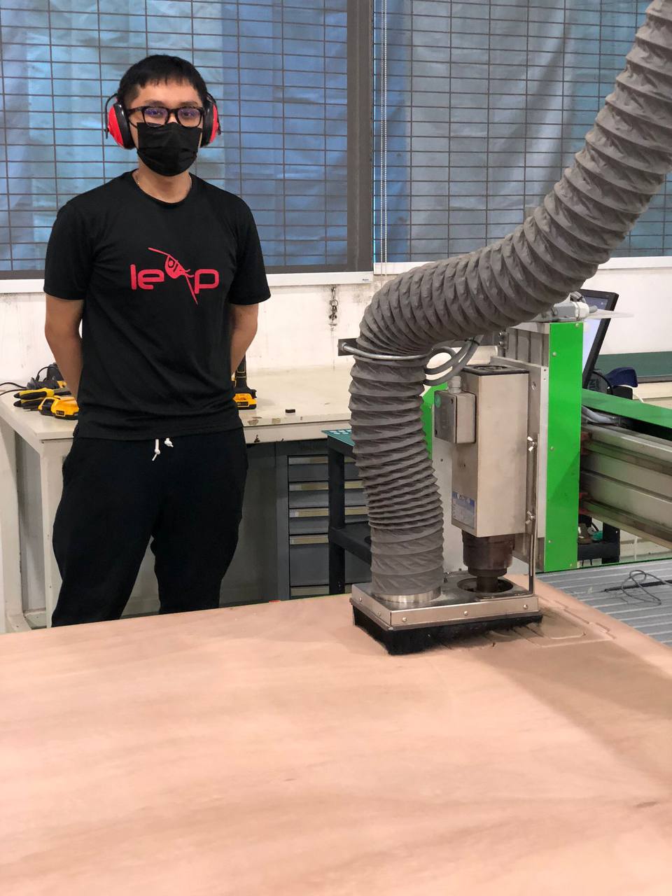
Some of the general things we have to look out for are:
- always have masks to prevent inhaling wood chips
- wear headphones/ear-muffs to protect ears, as it could cause long terms damage to the ears
- as in all labs, wear covered shoes and long pants
- if possible, wear eye protection goggles
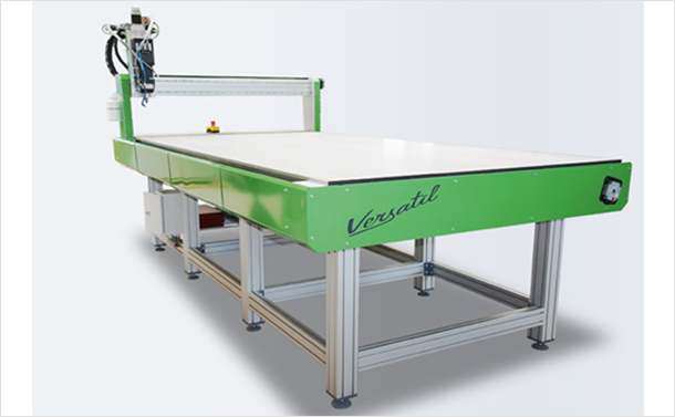
Our lab is equipped with the Versatil 2500.
We went through the steps of using the machine via a demo coaster by our instructor, Steven.
Below are the complete steps of using Versatil:
- Measure material depth and make adjustments
- Import dxf to V carve Pro
- Add tabs to ensure parts dont fly out
- (Optional) Pockets, specify depth of cut
- Add dog bone if not added in design, then group the components
- duplicate design if needed (nest components)
- Auto arrange parts for optimal arrangement
- Ensure 1 inch slope when cutting the design
- simulate path
- generate .tap gcode (separate files or in one file)
- Ask the lab officers to unlock for router
- Change work tool if needed
- Screw in material with wooden screw (Note: do not screw in where the bottom of board doesn’t have something to grip on, note the depth of wooden screw!)
- Turn on router
- Note: imagine the x axis as the long side of machine. As how the machine is situated in our lab, 0,0 is near the where user is (top left of router); positive x is to the right, positive y is to the top
- Start EasyNC
- Take note of 3 points: zero point where the machine indicates 0, a measure point, where the depth is measured, a cut start point where the cut begins (offset the screws!)
- Click reference (usually OK button to home everything)
- Use controller to move spindle to roughly measure point
- Place z probe, click measure, ensure spindle is above button, prepare estop
- Remove z probe
- Mark cut origin, Move x, y to cut point
- Start vacuum; ensure it has already been unlocked
- Check and double check SOP has been followed, and all general safety guides are followed
- Put on headphones/muffles
- Have the controller in hand, press start; ready for e-stop
- Ensure there are large chips, not powder. This is because powder cannot dissipate heat; only chips can
- After routing, vaccum away stuff, unscrew board, flip over
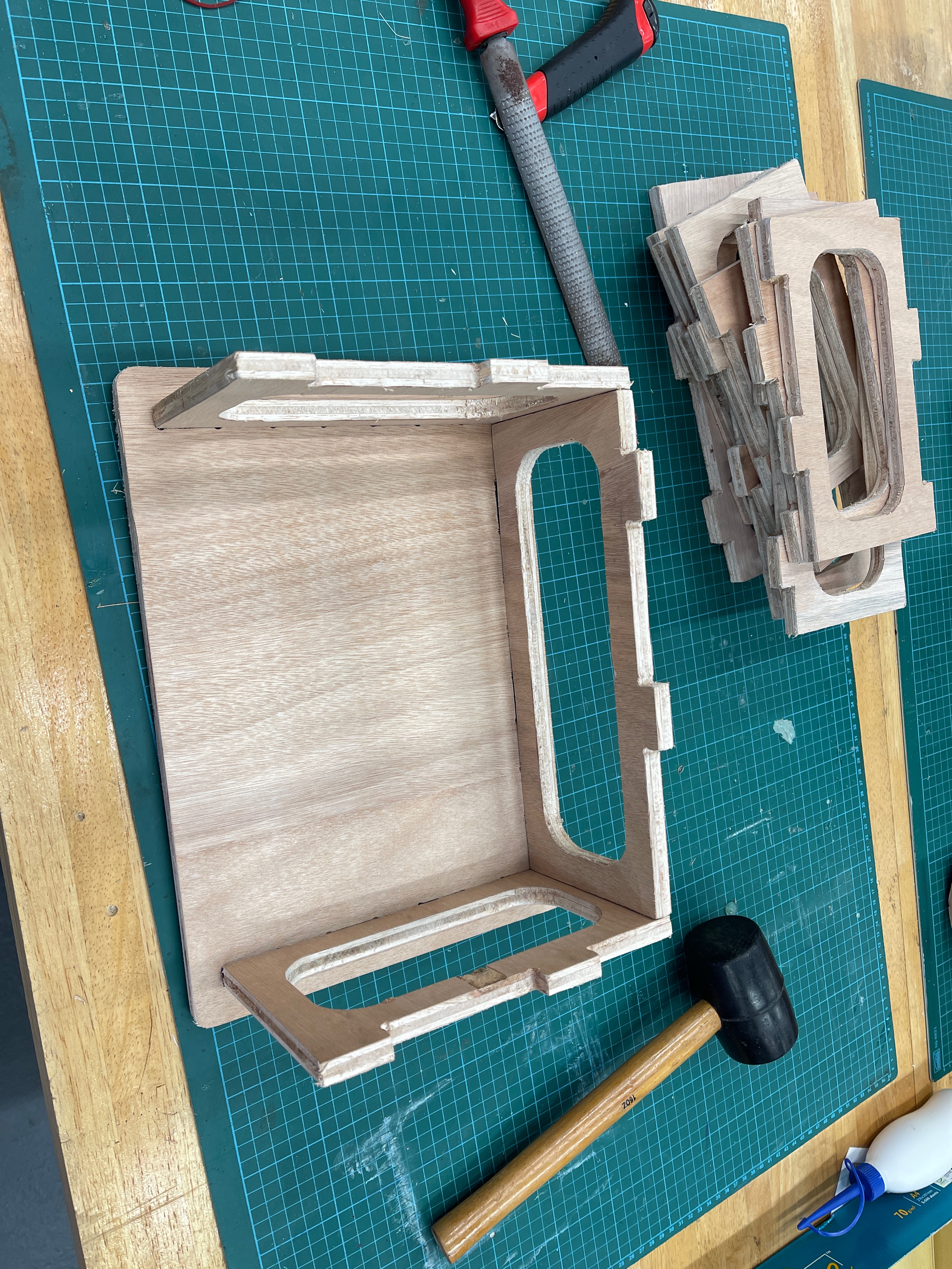
- Get chizel and rubber mallet, knock out the tabs from the back is the best as the cuts are clean
- Done
- Post processing (sanding, deburring, etc.)
Feedrate are based on tool used. Follow the vendor’s specifications. Depending on where the tools is acquired, check the specs and start from a lower bound for the tool limit. Remember: Safety First!
Design
Thinking of a design for this was not trivial. Initially, I wanted to work on some sort of furniture, but I wasn’t sure if it’ll satisfy being meter scale. I then thought of a simple design: if I had a modular shelf, I just need to duplicate it a few times and it’ll be meter scale right?
Updates to Global Evaluator
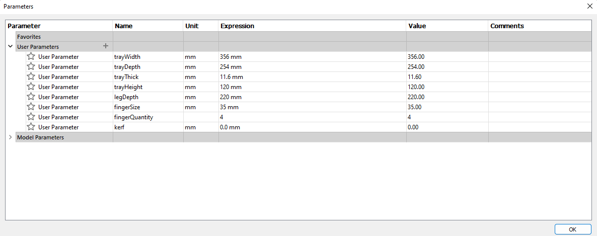
Based on the group project results, we found that if we did not want to disassemble the product, we should set the hole to be 0.1mm smaller than the key, or we can leave the hole to be the same size as the key if we planned to disassemble the product. Since I was planning to make the shelf modular, it means that most likely I will be disassembling it often, hence I set the kerf to be 0.0mm.
I set the thickness of the material as 11.6mm (indicated as trayThick).
End updates
Version 1
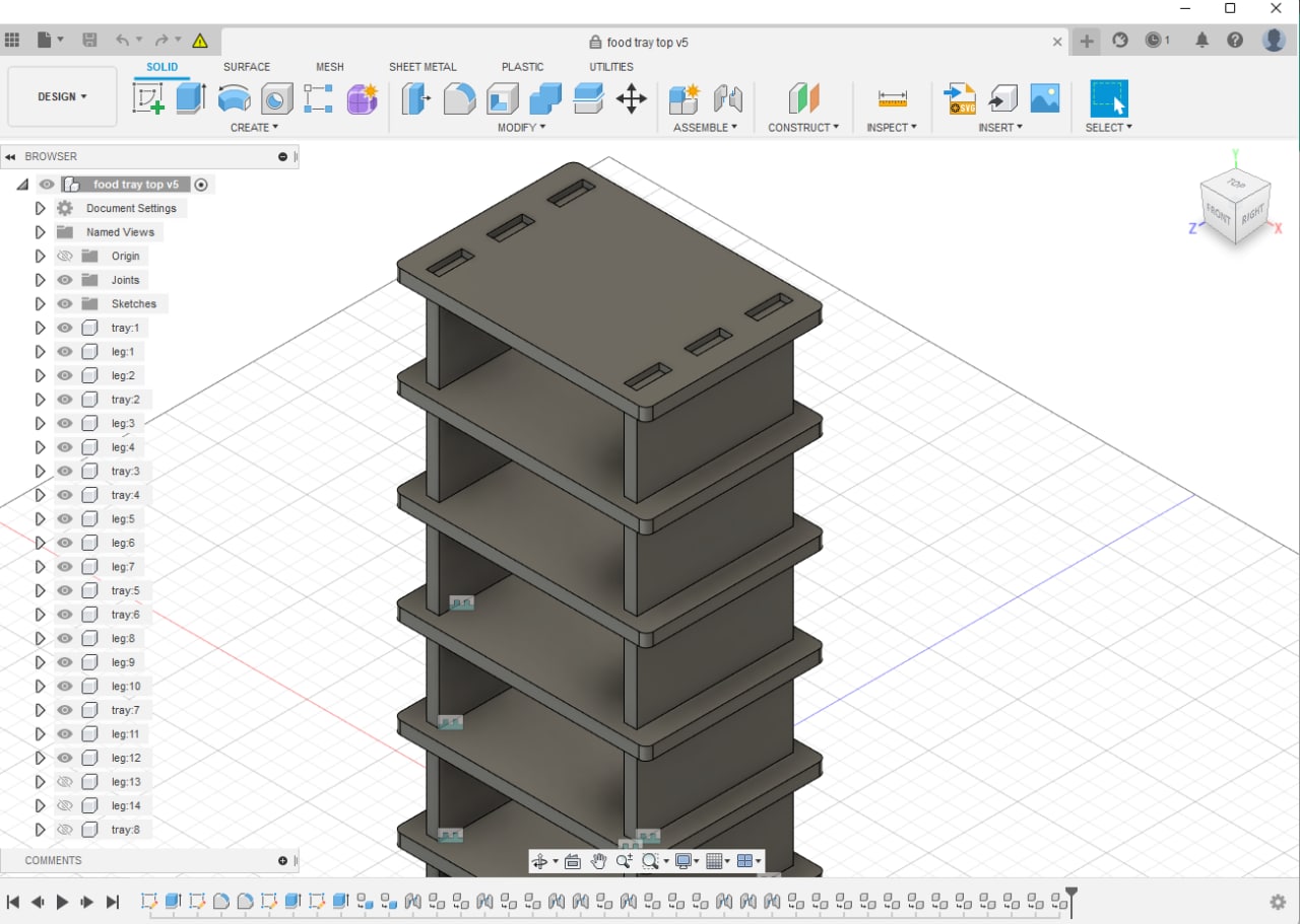
There are a few problems with this design:
- Sturdiness: The design is only supported on the two sides. A strong push might break the side panels and the entire thing will crumble.
- Size: Although sounds trivial, but I started by using finger joints of half the thickness of the board. given the thickest plywood boards we have are 18mm, this translates to only 9mm for each layer!
- Distances between holes: Similar with the depth of finger, given the separation between holes are only 10mm, it is not going to be sturdy, which may cause the parts to come off eventually.
I was so stumped as I was sure my design would be able to be milled without an issue given the design was simple. It just goes to show that simpler designs uncover bad design practices more easily :’) Nonetheless, I am grateful for all the feedback my instructor Steven gave to me!
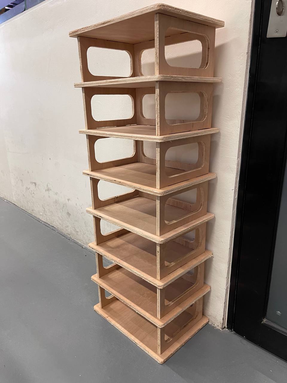
Version 2
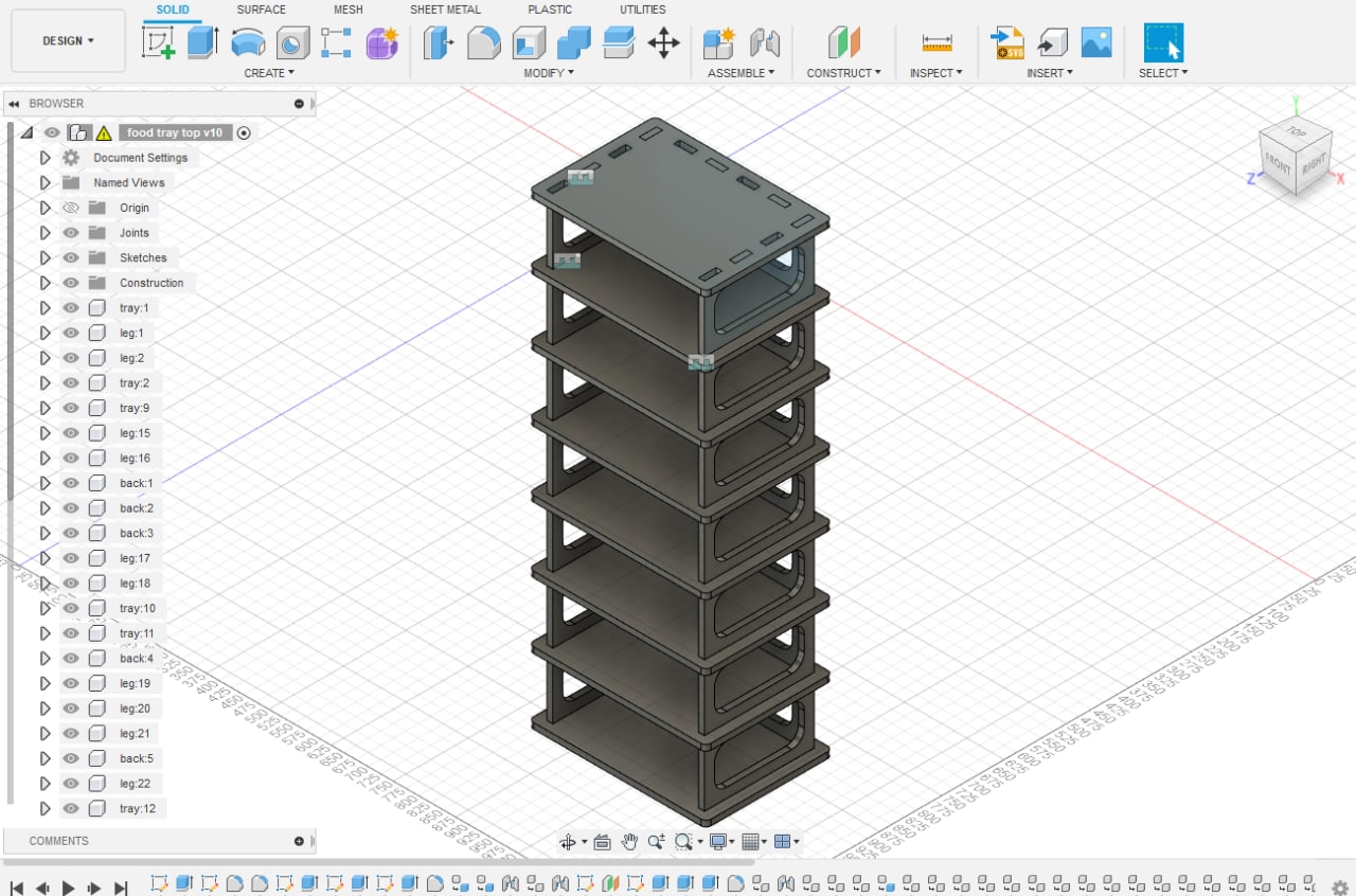
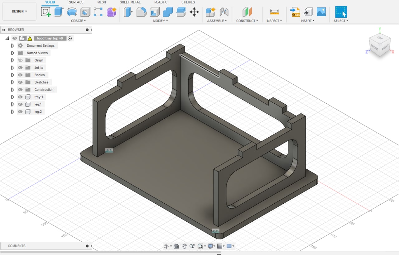
Some changes I did to mitigate the problems were:
- Make all the separation almost uniformly identical
- Alternate the finger joints, each sides are held up by roughly 2 pieces of fingers
- To reduce weight of the shelf, cut out the center of the board
- Ensure everything is parametric
- Add back plate for added stability
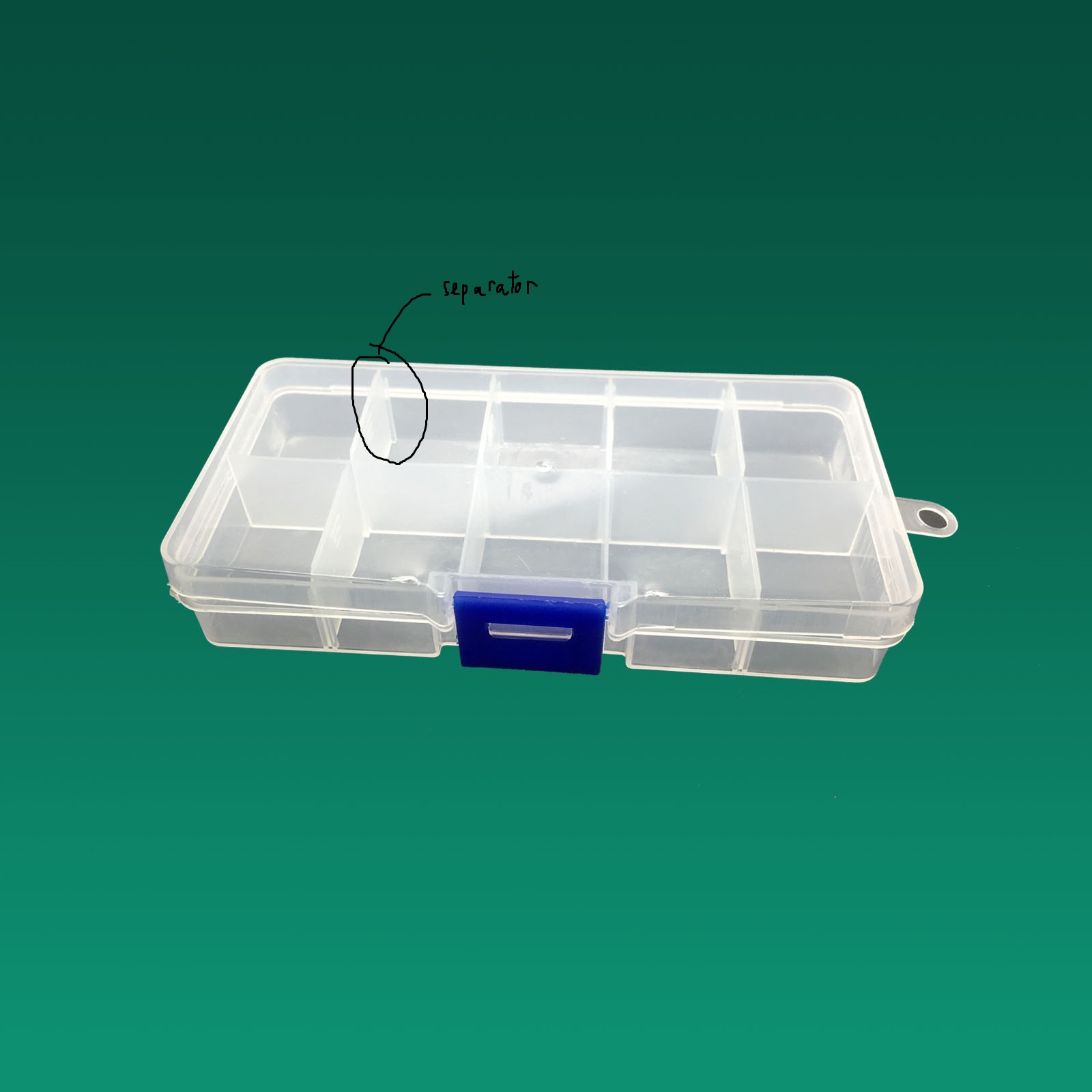
This ultimately leads to a relatively stable structure upon assembly. Although, this is not at all a good design, as a better design would have a limit on the size, and have removable middle sections of the shelf, much like an electronics component box separator.
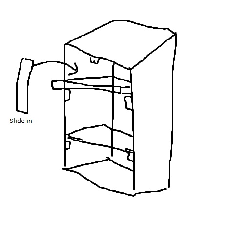
This however, required a major change and I simply did not have the time to redesign it that way. However, this likely means I will have another chance to use the large format CNC again in the near future for my final project.
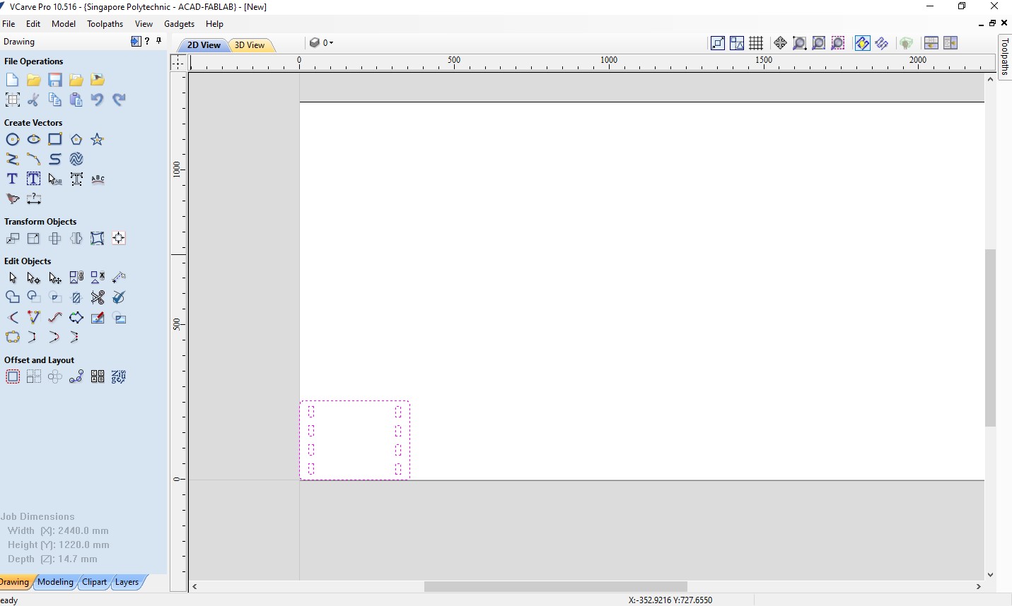
Operating V Carve Pro
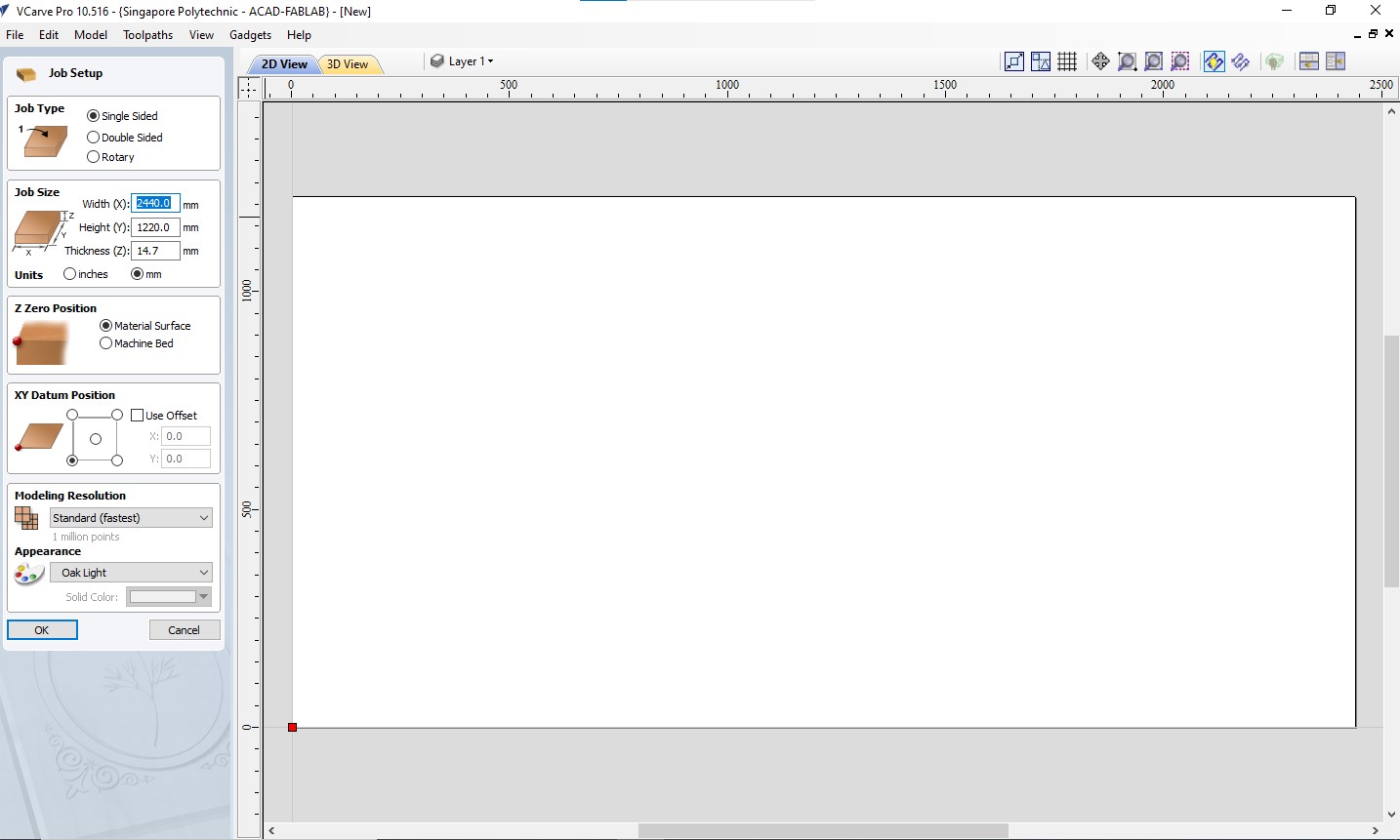
I used V Carve Pro to make final tweaks such as adding dog bone on corners and tabs to the design.
- dog bones are used to cut 90 degree cuts with minimal material removal.
- tabs are used to ensure the parts stay in place during cuts. They are later removed with a mallet and chizel.
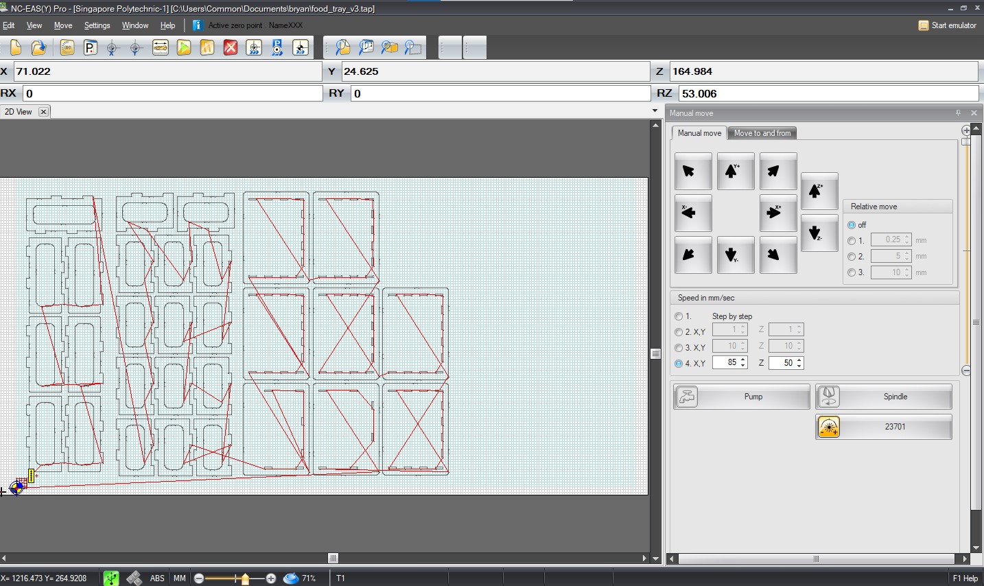
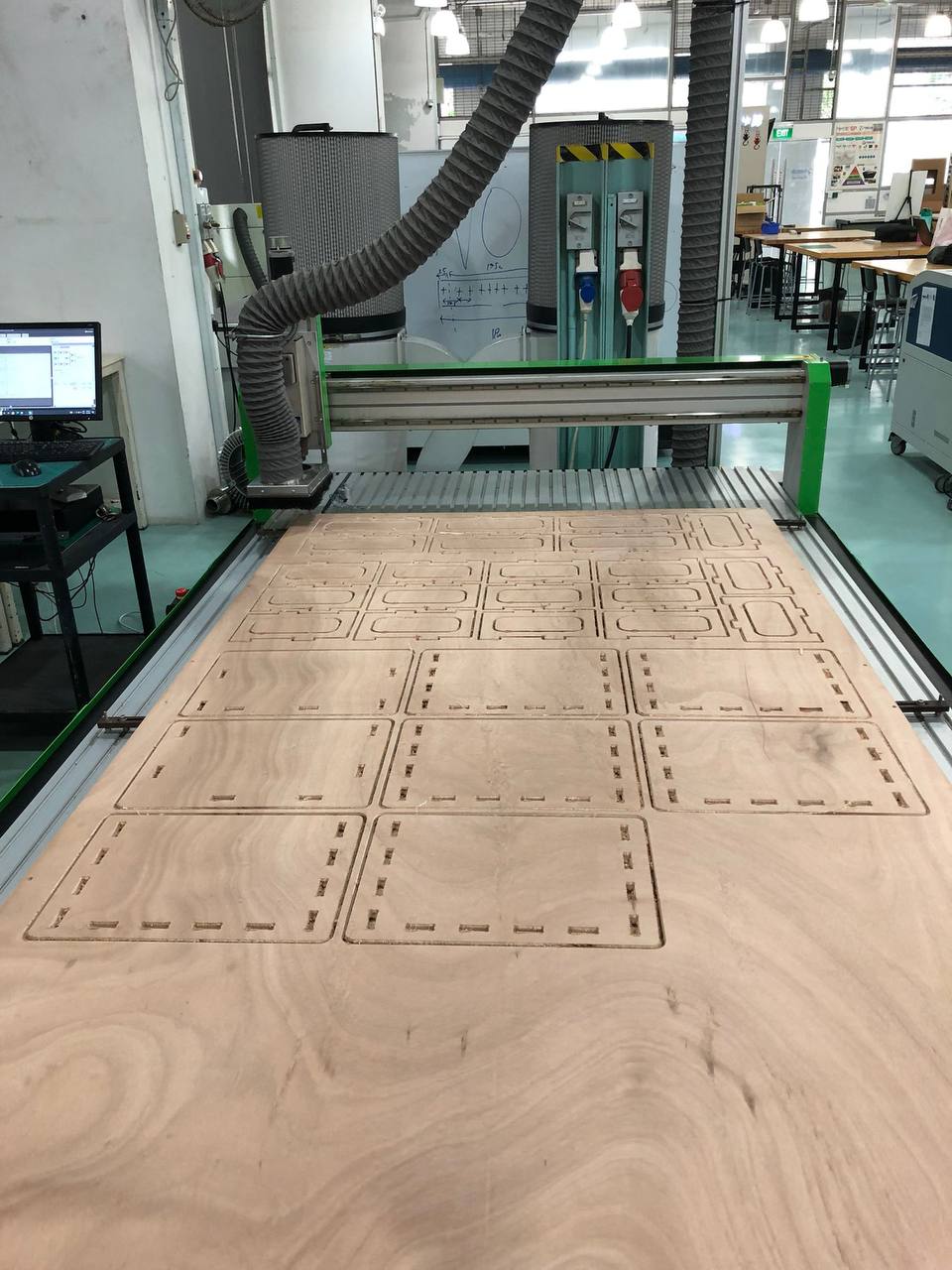
Using NC EASY
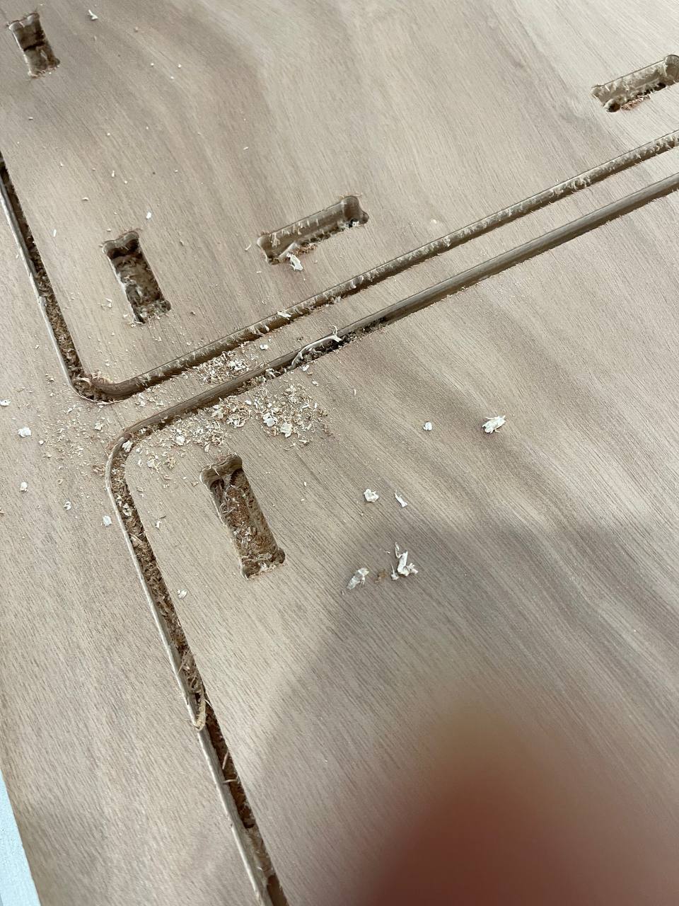
After using V Carve Pro, I exported the design files and imported them into NC EASY, which is the software to control the CNC machine. The cut was roughly 2 hours. I sat there and monitor the machine’s work. I was too afraid of accidents happening given what happened in my Electronics Production Week so I continued to stare at it milling away. The results of the cut was quite good!
Plywood thickness big oopsie…
I measured the width of the material to be 11.6mm. However, when Steven measured it, it was 11.9mm. I was shocked, as the difference isn’t “negligible” given the kerf is around 0.1mm!
I didn’t want to stop at saying I did a wrong measurement, as it is more important to know how I did my measurement wrong. I repeated my method of measurement a few times, and consistently got a value of 11.6mm. When I showed it to Steven, he mentions that I am pushing the Vernier Calipers too tightly, compressing the wood by just a little bit. I was shocked, as this was always the strength I used when vernier calipers to measure 3d prints. Perhaps it is a lot more significant on materials that can compress like plywood. I repeated a few more times to get the amount of strength roughly right, and tried my best to feel when I was “compressing” material.
What does this translate to the work required? All of my seven sections of shelf fingers, each level had 6 fingers, needed to be sanded and deburred. This was the main reason why I could not complete this assignment on time, which cascaded its ugly effect on the subsequent weeks.
Again, imagine this were a more complex design, this might be catastrophic in fixing, and if I had never seen this firsthand, I might never know I have been doing something wrong at all! I am grateful to have been able to learn from this experience.
Post processing
To reduce the side of the fingers, Steven suggested a fast way might be to compress the plywood with a G-clamp by just a bit before sanding and deburring, which might fix the size required (as it is only in that dimension the problem exist).

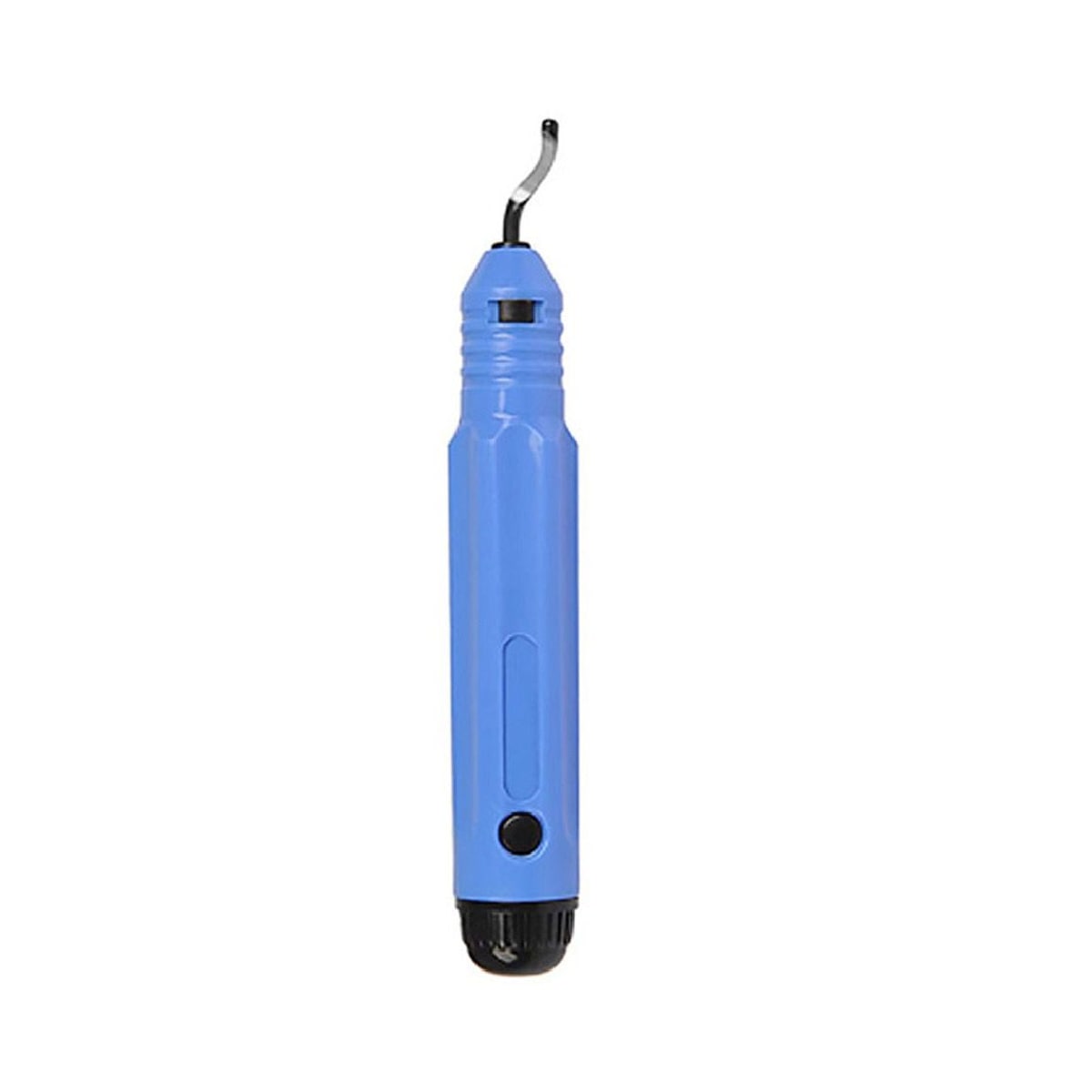
I was also introduced to deburring tools. Although in the end, I end up buying a box cutter because its more accessible and box cutter in labs are quite heavily used, might be better to get my own as it is quite a versatile tool to be used in many post processing steps for other machines.
However, here in Singapore we face a major hurdle: Our plywood suppliers only import bulk from Indonesia, which the woods are of lower grade. My cutting results, according to Steven, are considered clean cuts, and should be easy to preprocess. But all the pieces were so fibrous! I was not looking forward to cleaning up the cuts.
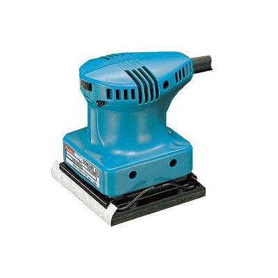
I was also provided with an Orbital sander. This tool really helped simplifying the process.
Essentially, with those tools, I made some pretty good progress. Keeping track of time, I took roughly 25 working hours to complete the cleanup process.
The lesson here: make something simple, learn from something simple, and improve on the complex designs in the future.
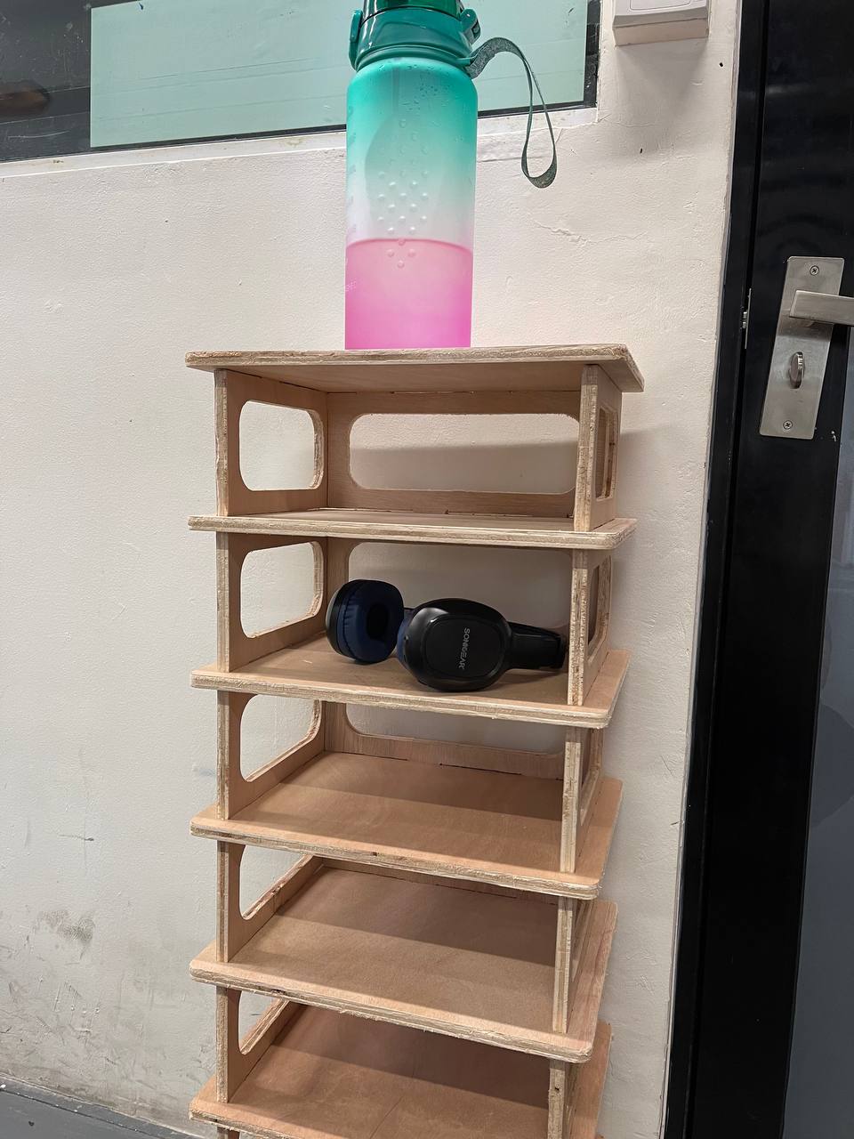
Hero shots
Conclusion
Attention to detail and getting a second pair of eyes on your work, while time consuming, will definitely save precious time. This also goes hand in hand with document as you go, and will be something I need to continue to work on. Nonetheless, I am happy to have gone through the process!