Appendix B
Click here to return to main page.
Here contains some information that was not relevant to the current spiral. Evaluators can ignore this section.
Power System
Why does this constitute a separate section?
Currently, the entire system is powered by a lab bench power supply. To make the robot complete, we need to have some minimal way of connecting power to the system. To do so, we need to define a few things
- How much power would we need?
- How long does the robot run?
- What characteristics would the robot exhibit?
How much power?
| Part | Power |
|---|---|
| Steppers | 1.2A@12V x 3 = 43.2W |
| Electronics Components (microcontrollers, sensors etc) | <1A@5V = 5W |
| ESP-01 | <500mA@3.3V = 1.15W |
| Total | 49.35W |
How long does the robot run?
Ideally, the robot would be operating for around 3-5 hours. For this spiral, I plan to aim for roughly 1-3hours as a proof of concept. So, we can put an upperbound as roughly 150Wh.
Assuming that the battery pack operates at 12V, we will need a battery pack with capacity of at most:
and at least
What characteristics would the robot exhibit?
Likely, the robot will take constant current when it is operating. However, it will await for orders once in a while, and deactiavte the motors completely. When that happens, the robot will take around 6-7W of power. We can think the robot as operating in bursts.
Type of battery that is suitable
Based on these calculations, I wanted to try out these types of batteries
- Li-Ion
- Li-Po
Li-Ion
|Property|Value| |Voltage|3-4.2V| |Capacity|2300-3600mAh|
If we were to go with these types of battery, we will need at least 3 in series. That would come out to be around 9V - 14.4V
To use this battery however, I would need a BMS to safely charge and discharge each cells. A brief explanation is that each cell has slightly different chemical composition, and hence charge and discharge at different rates, even if they are from the same brand/model/company. The danger comes when the cells are different voltage and are connected to each other, where they charge and discharge each other with virtually \(0{\ohm}\) between them. A BMS remedies this by having a mosfet and a charging/discharging circuit in place.
However, building this and verifying that it works is far too dangerous. It would be better for me to just buy one. However, shipping of this will take some time, and thus I will move on to use a different battery system instead.
There is, however, an open source design available. I plan to experiment it in the spiral after. It also includes a BOM at the bottom, so that’ll definitely be at least one of my weekend projects after FabAcademy

How to wire the batteries
To wire the batteries properly, we need to implement the following:
However, to place a soldering iron on top of the battery without thinking too much is essentially a suicide mission. The proper way to join the batteries together is via a technique called spot welding.
Spot Welding
Steven showed me how to do spot welding, which to me was very interesting. To do this, we need a dedicated spot welding machine.
- Cut Nickel plate to the correct size
- Place the Nickel plate at the desired location
- Configure Spot welder (1.4 power, 3s delay)
- place two probes on the nickel plate, aim to do 2 spot weld joints (so it generates 4 dots on the nickel plate)
Ultrasonic integration
Ultrasonic control board to main microcontroller
While this was excluded from the current spiral, I figured it is still good to write what I have found and explain why I have decided to omit this from the spiral.
- For all ultrasonic sensors to work in tandum we need to poll the microcontroller for the distance it is currently seeing.
- Setting it to be a default 1m would cause the polling of each ultrasonic sensors to take a long time. As such, it defeats the purpose of avoid nearby objects swiftly.
- The ultrasonic sensors wait for a frequency to return to the echo sensor, which is usually generated by the paired trigger pin. However, setting the sensors to be 120 degrees apart has some weird issues with all 3 sensors receiving readings from a the same trigger pin. Meaning that while the robot is staring at a wall in front, it sometimes cannot determine where exactly the wall is. This is a huge problem that needs some further investigation.
I did not include any images or videos here, as I think text is good enough to represent the problems I have faced.
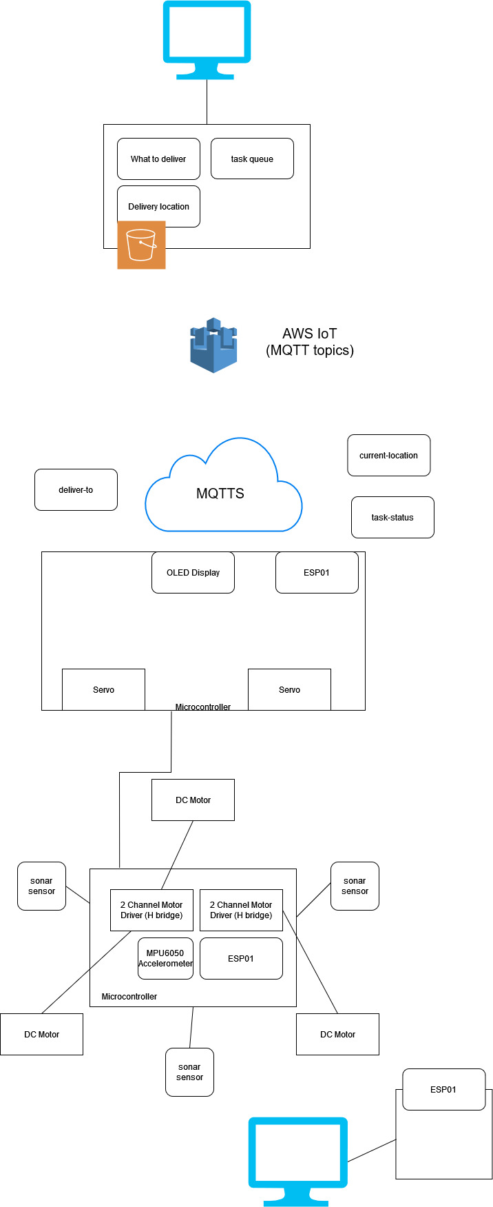
High level architecture
Click here to return to main page.