12. Mechanical design
assignment
group assignment
-
design a machine that includes mechanism+actuation+automation+application
-
build the mechanical parts and operate it manually
-
document the group project and your individual contribution
3D printing Files
Laser cutting Files
CNC milling files
Designing the machine
I’m going to build a machine based on the CoreXY mechanism :
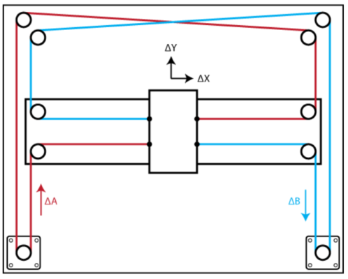
Both motors control the X and Y axis at the same time :
-
If both motors turn in the same direction, the head moves in the X axis
-
If both motors turn in the opposite direction, the head moves in the Y axis
-
If only one motor turns, the head moves in diagonal
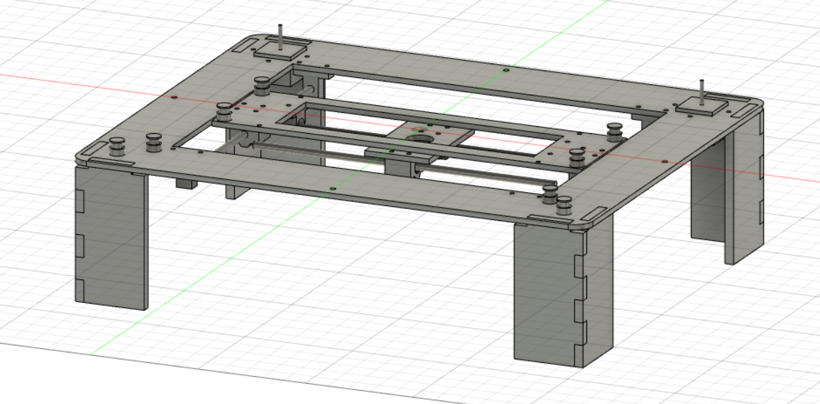
I started by making the design on fusion 360 :
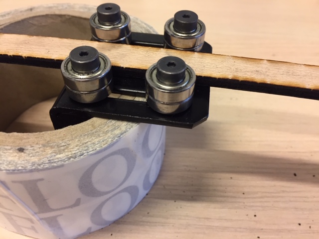
and making a test machine with cardboard. I initially went for a guide with rail but the mechanism was too loose so I switch to a guide ring :
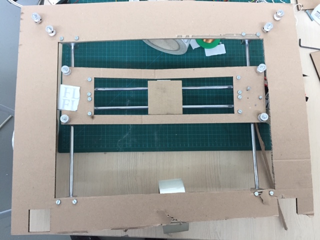
Testing the mechanism :
Laser cutting and 3D printing parts
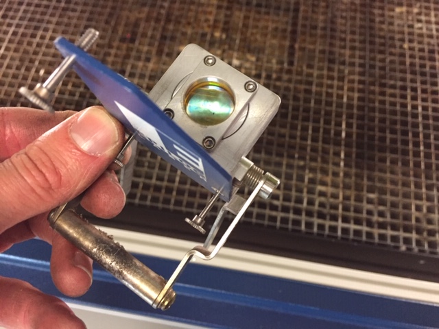
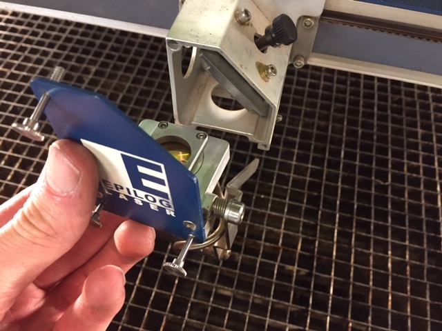
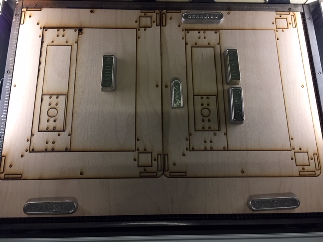
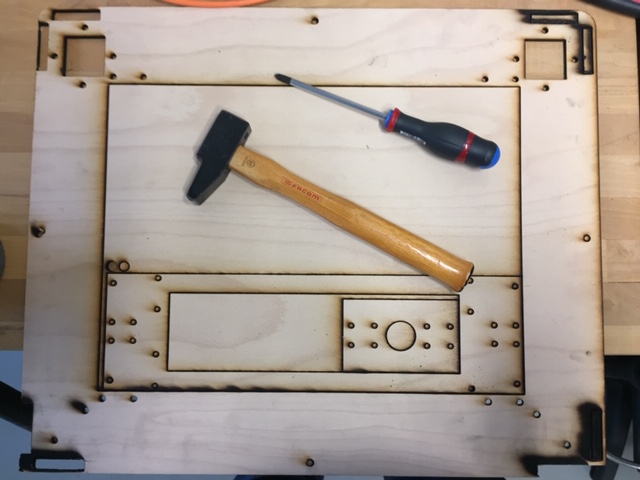
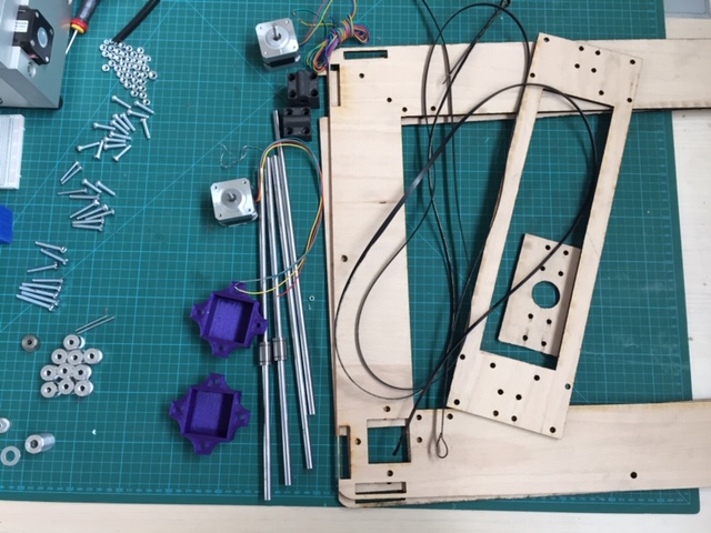
Then cutting the parts on 5 mm plywood. To do that, I changed the lens for a 3 inch one which allows to almost cut through it with one pass (I had to brake apart some pieces with a hammer):
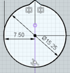
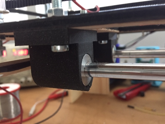
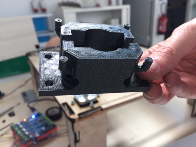
I also printed extra pieces for guides. I drew the cylinder with a tear shape to avoid overhangs and make the insertion of the ring more easily :
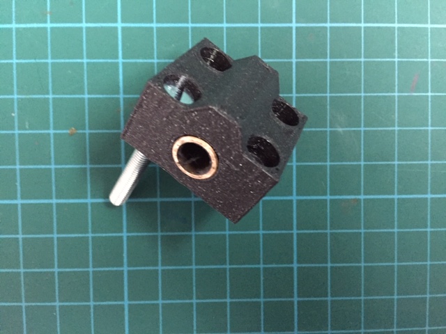
Slide stop and modular head to insert different end effectors :
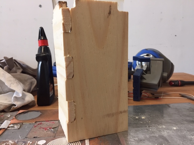
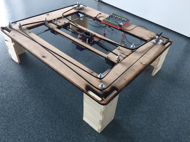
Legs milled on CNC machine to support the CoreXY machine :
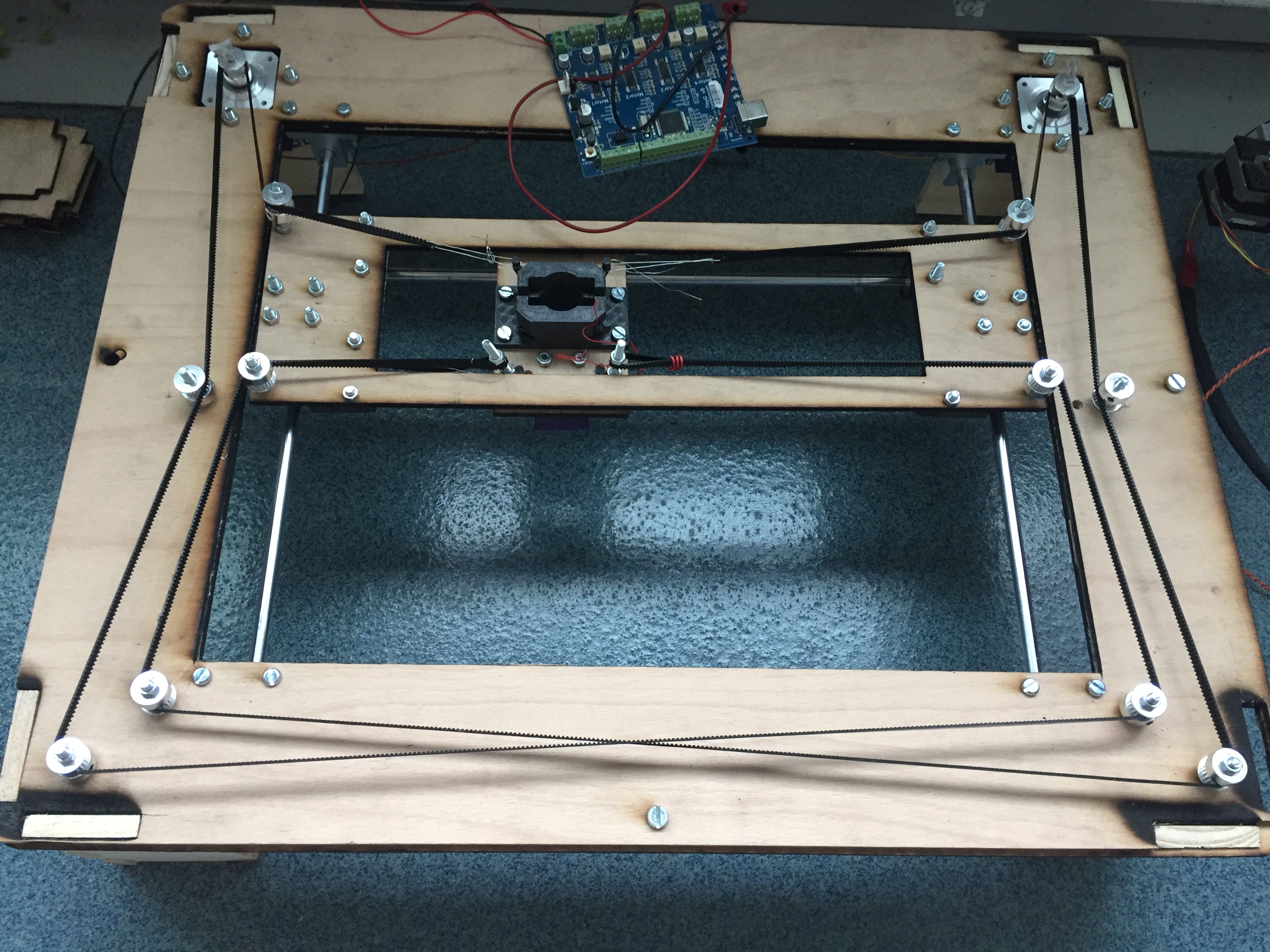
Building the machine :
Actionning the motors
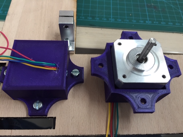
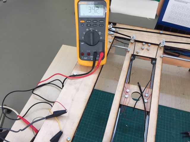
I’m using two stepper motors NEMA 17.
There are 4 wires, 2 for each coil. To see which ones are connected to the same coil, I used the multimeter with the ohm meter function :
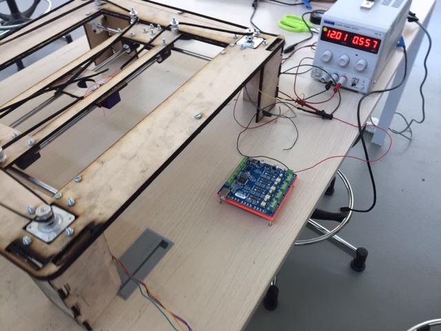
to control the motor I used a TinyG board and Chilipeppr software :
Documentation about TinyG
Setup Chilipeppr
-
Controlling it with JSON
-
$1ma=0 – set the 1st motor of tinyG to the X axis
-
$xvm=200 – set the speed of the X axis
-
$1sa=2 – set the step angle of the 1st motor
-
G0 X1 to move to x = 1
Setup the step angle :
Move along an axis :
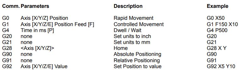
Gcode
I looked for Gcode commands :
I then operated each motor, looking how the head (end effector) would move. Below are my observations, where y is the vertical axis and x is the horizontal axis :
| Motor 1(X) | Motor 2 (Y) | Head movement |
|---|---|---|
| + | - | x- |
| - | + | x+ |
| - | - | y+ |
| + | + | y- |
| - | = | diagonal 1 (y+x-) |
| + | = | diagonal 1 (y-x+) |
| = | + | diagonal 2 (x-y-) |
| = | - | diagonal 2 (x+y+) |
I wrote a Gcode based on those observations where the head would move to 6 different points. The head should move to 3 points in a line and to 3 other points on a parallel line to the first one. Then come back to the origin :
G1 F25          ; set the max speed
G1 Y2           ; move diagonally to 1st point
G1 Z-1          ; operate end effector
G1 Z0
G1 X-1 Y1       ; move to 2nd point
G1 Z-1
G1 Z0
G1 X-2 Y2       ; move to 3d point
G1 Z-1
G1 Z0
G1 X0 Y-2       ; move to 4th point
G1 Z-1
G1 Z0
G1 X1 Y-1       ; move to 5th point
G1 Z-1
G1 Z0
G1 X2 Y0        ; move to 6th point
G1 Z-1
G1 Z0
G1 X1 Y1        ;move back to origin
G1 X0 Y0
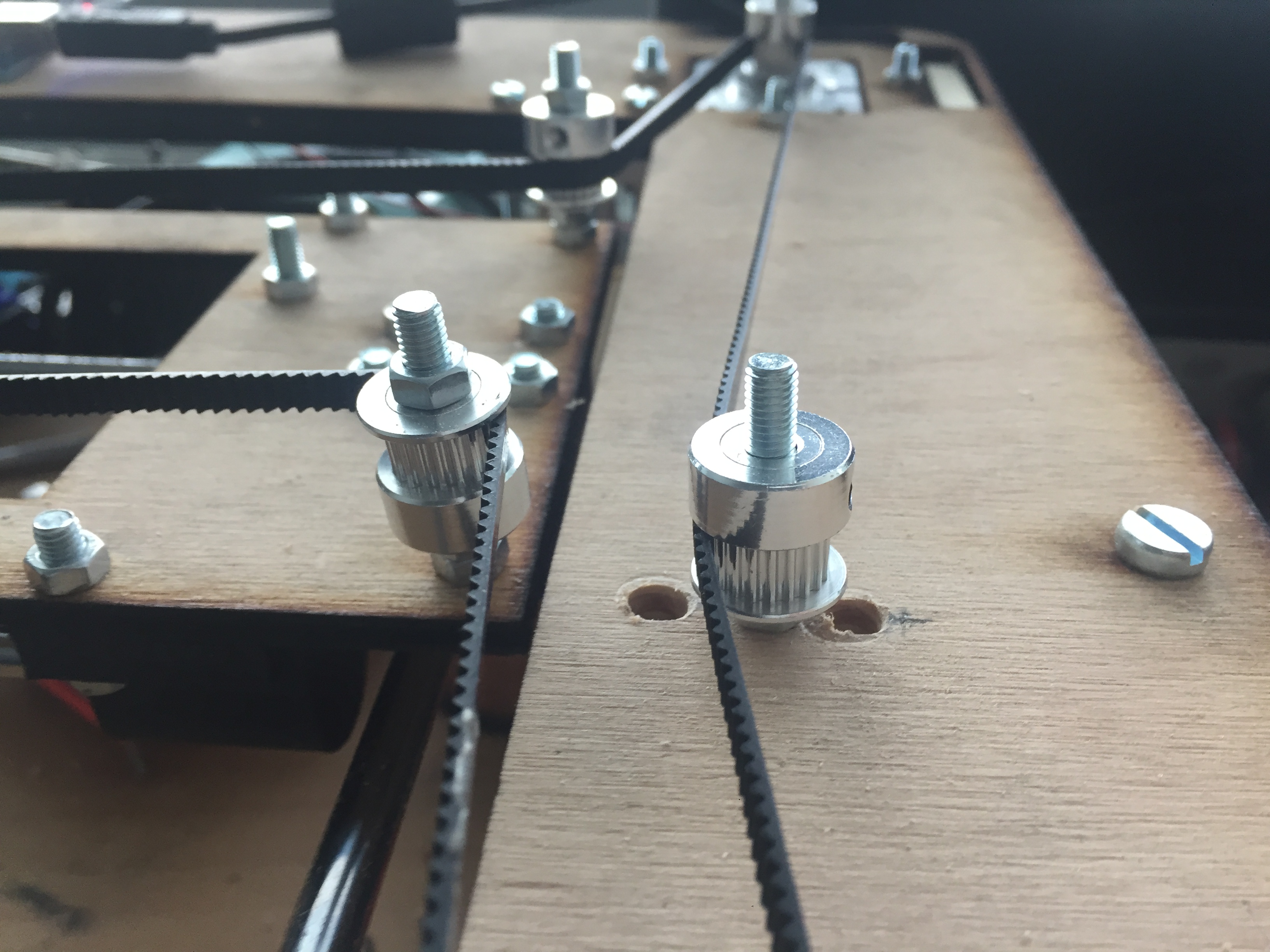
The movement on the x axis is jerky probably due to the lack of tension of the belt. Also I inverted the x and y axis so the movement is inverted (which in this geometry is not impactful)
Belt tensioner
There is not enough tension on the toothed belt. I made a belt tensioner inspired by timing belts of cars but I have to adjust it manually. I made 3 notch to adjust the tensioner :
End effector
To be done…
Conclusion
The system I chose was probably too complex to be done alone. It took me way more time to test the motors than I expected and it was by far the most difficult assignment to date. I didn’t have time to test the end effector.
On the Gcode part, I was able to write a simple Gcode and move the machine on the xy plane.
observations
I noticed that the conversion to the coreXY is making a rotation of 135° as long as we don’t use diagonal movements. So I could be able to draw the path on a vector program like Inkscape nd make rotation of 135° to have the wanted path on CoreXY. But I didn’t test it
Looking on this Instructables, I need to upload the coreXY_plotter.ino to an arduino board which is plugged to CNC controllers (BigEasy driver in the case of the Instructable).
The arduino programm converts a simple Gcode (where one motor is linked to one axis) to the CoreXY configuration.