14. Networking and communications
Assignment
individual assignment:
design, build, and connect wired or wireless node(s)
with network or bus addresses
group assignment:
send a message between two projects
Bluetooth files :
KiCad files :

<a href="../../files/Bluetooth_antenna.kicad_pcb">KiCad PCB</a>

<a href="../../files/Bluetooth_antenna.kicad_sch">KiCad schematic</a>

Code Arduino :

<a href="../../files/led_BLE_ledstrip.ino">Code Arduino</a>
I2C protocol program :
Gantt plan of the week
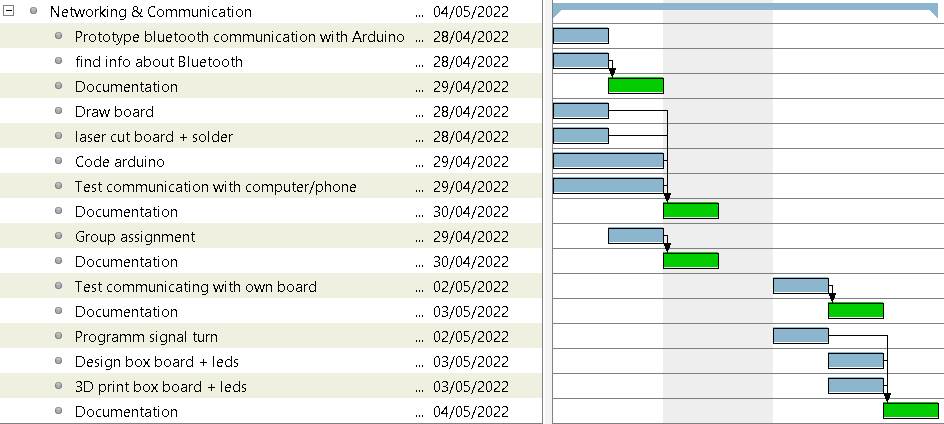
This week, I plan to try the Bluetooth communication with my phone or computer and my board. And improve the project I made to prepare this fabac : Signal Turn
Prototyping with Arduino 33 BLE sense
I started this week by following this tutorialto control LEDs through bluetooth with my board arduino 33 ble sense which has a bluetooth module (u-blox NINA-B306)
Learning about Bluetooth
- Bluetooth services have an UUID value which correspond to the type of data send
- There is also an UUID characteristic. Here we define a digital Output which has a value of “2A57” according to the bluetooth-numbers-database/characteristic_uuids.json at master
- There is a central device and a peripheral device (new names for “master” and “slave”)
Following the tutorial, we have to define the service to “180A” which corresponds to the mnemonic : org.bluetooth.service.device_information and the characteristic to “2A57” for Digital Output.
BLEService ledService("180A"); // BLE LED Service

// BLE LED Switch Characteristic - custom 128-bit UUID, read and writable by central
BLEByteCharacteristic switchCharacteristic("2A57", BLERead | BLEWrite);
set the name of the device and add service :
// set advertised local name and service UUID:
BLE.setLocalName("Nano 33 BLE Sense");
BLE.setAdvertisedService(ledService);

// add service
BLE.addService(ledService);
I installed the LightBlue app on my phone and with that, communicating with the phone. Sending a 0x1 turn on the LED in red, 0x2 in green and 0x3 in blue :
Design + production of the PCB
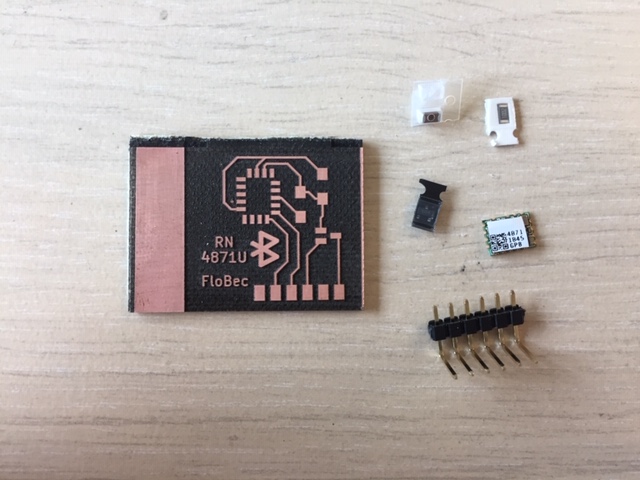
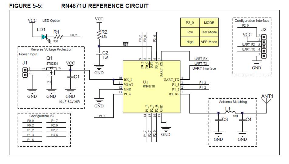
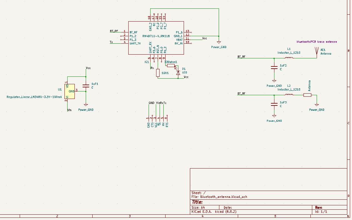
The bluetooth module we have at fablab Digiscope is the RN4871U which is almost the same model as one of Neil’s board. I’m going to build a board based on this design. Only the pinout changes. Looking at the pinout diagram :
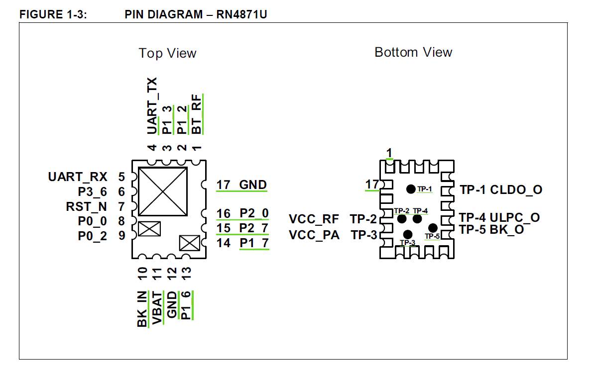
There is a 3.3 V LDO, because the module has an operating voltage between 1.9 V and 3.6 V.
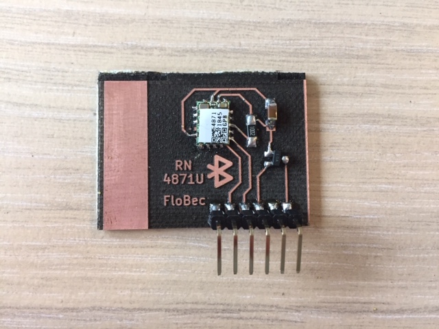
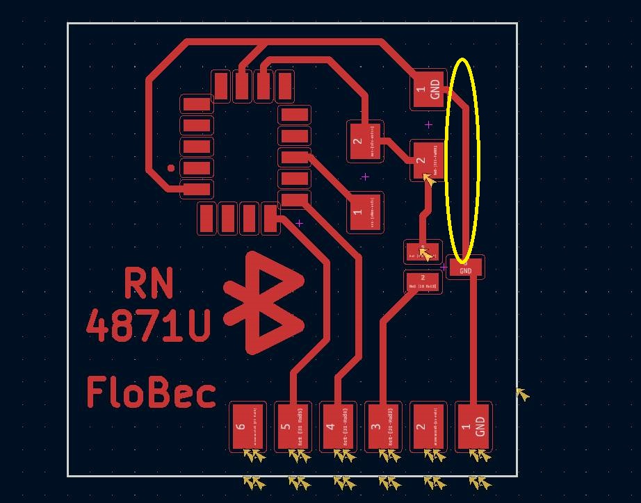
I designed the PCB in KiCad :
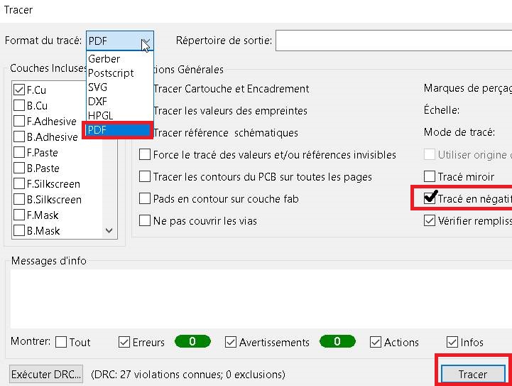
saving the file as PDF on KiCad
in File -> plotter :
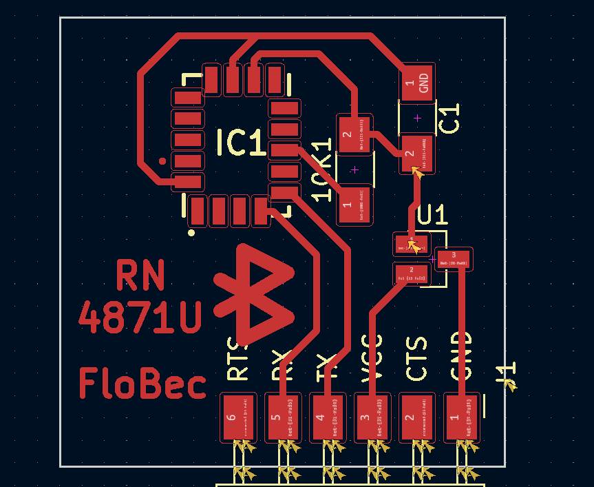
Missing GND liaison :
Programming module
To make the bluetooth device work, I checked several documentations about that which I’ll link below :
Online documentation
Tuto from GoTronic but it’s not the same module
Arduino example for the RN487X library
Another tutorial for RN487X chip
Neither of these examples worked
I also checked some useful Fabacademy sites :
Fabacademy sites :
Joris Navarro has a good doc on how to reproduce Neil’s example for RN487X.
Step by step bluetooth serial computer with python :
pip install pyserial
python miniterm.py COM5 115200
if for some reason you have the following message :

write the full path :
python AppData/Local/Programs/Python/Python39/Lib/site-packages/serial/tools/miniterm.py COM5 115200
Replace the port by the good one (it was COM17 for me)
Then enter $$$ to enter command mod followed by +
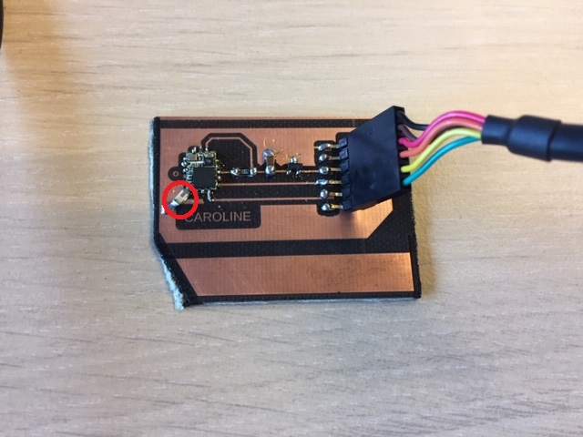
I got stuck in this part. typing $$$ doesn’t do anything for me. Even when echo is on. When trying to scan for bluetooth apparels with different apps (LightBlue and Microships atmel smartscan), my device doesn’t appear. I also tried with another student -Caroline chaumeil’s card which I didn’t manage to make it work either.
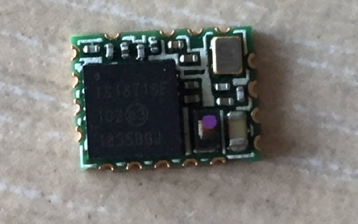
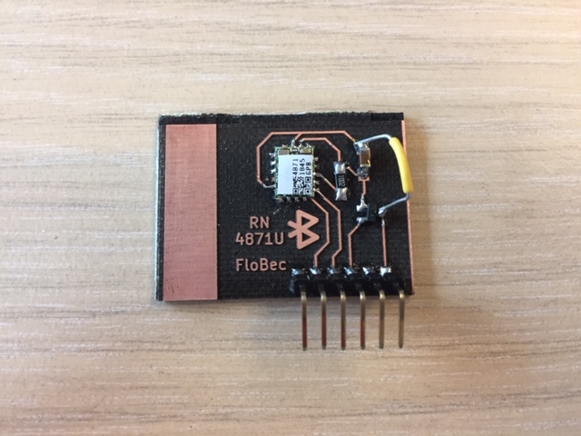
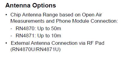
The problem may from my device. Double checking the datasheet, the RN4871U chip does not have an external antenna ! So I made a test with an artisanal antenna :
And a chip which was unsoldered from an Arduino board :
Not much success either. I’ll try the example circuit of the datasheet for this chip :
Designing my own antenna
The antennas we have at the fablab are quarter wave-antenna for radiofrequency. Its length is the quarter of the wavelength corresponding to radiowaves.
For Bluetooth, I would need a shorter antenna. The frequency used is around 2.4 GHz in the ISM (Industrial, scientific, medical) band range.
So for f = 2.4 GHz, Λ = c/f where c is celerity and Λ the wavelength :
Λ = 12.5 cm so the antenna should be around 3cm for bluetooth.
Useful documentation :
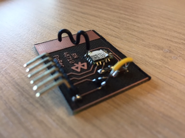
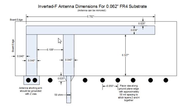
The impedance of the antenna should be 50 ohms, the documentation gives a 1.4 mil width for a 0.008” copper thickness for this impedance. I edited a new footprint in KiCad. I made the possibility to use 2 antennas, PCB trace one and a chip one :
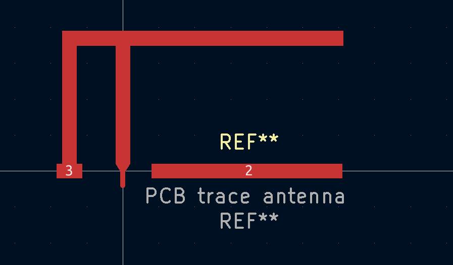
New design on KiCad :
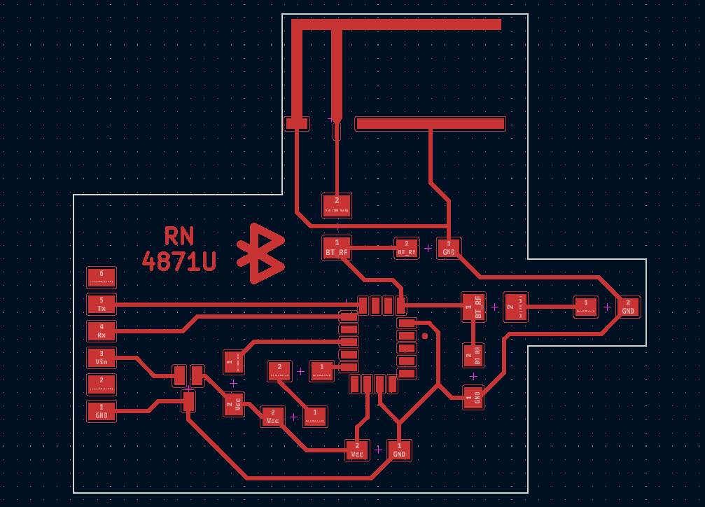
New board soldered. The part with the chip antenna has been damage, but I still have the PCB trace antenna. Also we don’t have 1nH inductor in the fablab, so I just put a 0 ohm resistor instead :

Not much success either. Impossible to enter command mod in the serial terminal.
I2C communication
I didn’t manage to make the communication between a board I made and another board with Bluetooth, so I’ll try with I2C communication :
I2C is a protocol of communication between wired chip. One chip which is the master/controller and all other circuit are slaves/peripherals. The controller always starts the communication.
The protocol is using two different lines : a serial clock line (SCL) and a serial data line (SDA). And the ground should be the same for all the boards :
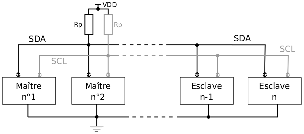
There is a 10K pull up resistor on SCL and SDA.
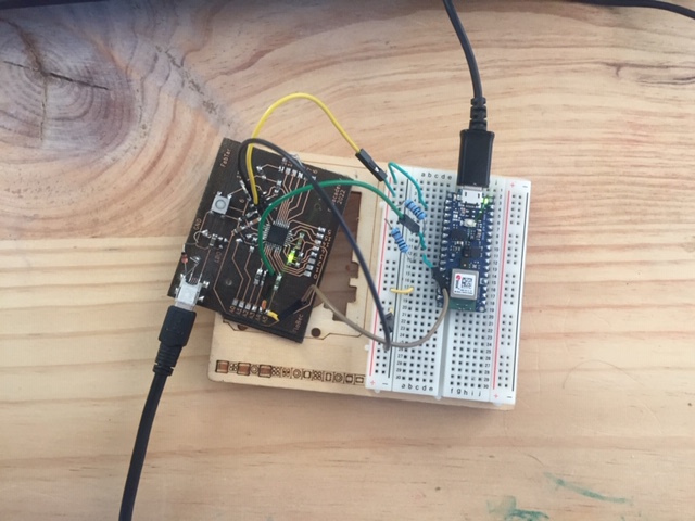
I’m following an example from this tutorial between the board I made in the Output devices week and an arduino nano 33 ble sense :
The SDA and SCL are respectively on the A4 and A5 pins for both arduino nano 33 and atmega 328p.
Programming
Arduino uses the library Wire.h to use the I2C protocol. I uploaded the following code to my board. This board will be the “reader” : it’ll get the data coming from the arduino board and turn on or off its led depending on the value :
#include <Wire.h>

#define LED 13

void setup() {
  Wire.begin(8);                // join i2c bus with address #8
  Wire.onReceive(receiveEvent); // function that executes whenever data is received from writer

  pinMode(LED, OUTPUT);
}

void loop() {
    delay(100);
}

void receiveEvent(int howMany) {
   char c = Wire.read(); // receive a character
   if(c == '0'){
     digitalWrite(LED, LOW);   // turn the LED off by making the voltage LOW
   }
   if(c == '1'){
     digitalWrite(LED, HIGH);  // turn the LED on (HIGH is the voltage level)
   }
}
The line Wire.begin(8) set the board with the address #8 in the bus.
Then I uploaded the following code to the arduino nano board. It will be the “writer” : it receives a value send in the serial port from the computer and send it to the other board :
#include <Wire.h>

void setup() {
  Serial.begin(9600);
  while (!Serial);
  Wire.begin(); // join i2c bus (address optional for writer)
}

void loop() {
  Serial.print("Enter 0 to turn off led, enter 1 to turn it on ");
  char ledVal[0];
  readSerial(ledVal);
  Serial.println(ledVal);
  Wire.beginTransmission(8); // transmit to device #8
  Wire.write(ledVal);        // sends the given value
  Wire.endTransmission();    // stop transmitting
  delay(500);
}

int readSerial(char result[]) {
  int i = 0;
  while (1) {
    while (Serial.available() > 0) {
      char inChar = Serial.read();
      if (inChar == '\n') {
        result[i] = '\0';
        Serial.flush();
        return 0;
      }
      if (inChar != '\r') {
        result[i] = inChar;
        i++;
      }
    }
  }
}
The line Wire.begin() without any adress sets this board as the master/controller.
Setup
Here is my setup :
The monitor prompts this message :
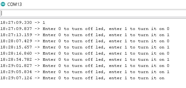
Result in video
When typing 1 and 0 on the serial monitor, the LED on the reader board turns on and off :
Programming my own app to control LEDs via Bluetooth
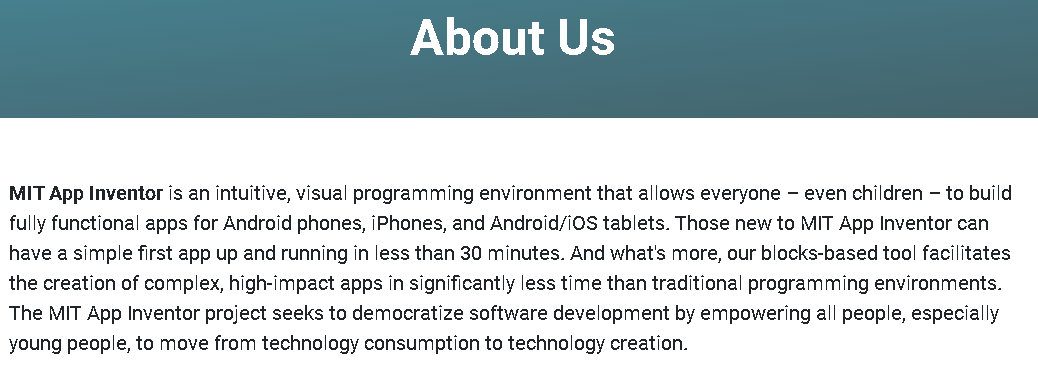
I don’t have any knowledge on app development so the first step was to find a good app builder. Most of them are free until you want to put it on the store. I finally stumble on the MIT App inventor from looking to previous fabac docs. This app is under the Creative Commons Attribution 4.0 International license :
To use bluetooth on the app, I looked at this tutorial
The programm made above on Arduino uses Hex data to tell to the board which button has been touched. I found the following function in the app forum to convert the data into hex :
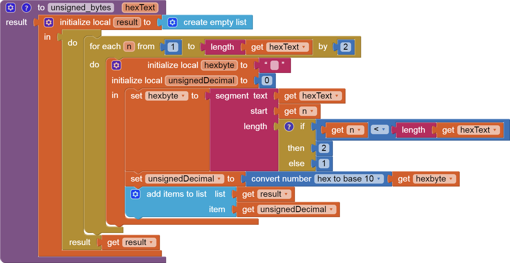

Note
-
The bluetooth extension on the MIT app inventor is not yet implemented with the IOS
-
One last thing, I used the function WriteBytesWithResponse instead of WriteBytes because the latter didn’t work
video :