11. Output devices
Assignment
individual assignment:
add an output device to a microcontroller board you’ve designed, and program it to do something
group assignment:
measure the power consumption of an output device
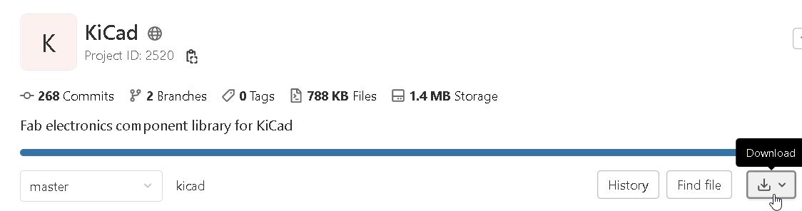
Download files :
KiCad files :
Hex file :
Gantt plan of the week
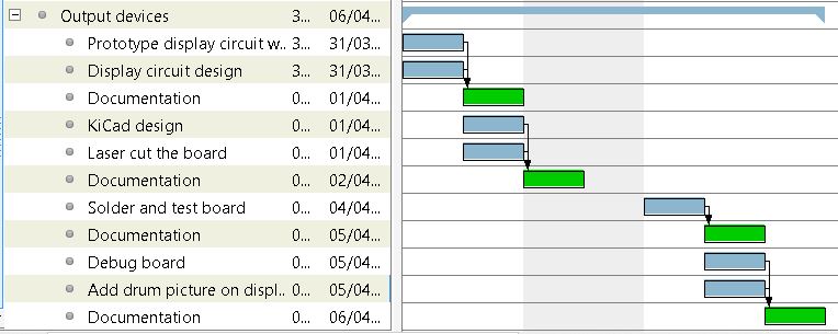
This week I plan to make the display for my final project. This screen will allow me to display the choice of drum set I make and the sound level.
Prototyping
My principal criteria is to have a circular display which fits well into my design. I found this display in GoTronic. It is TFT with SPI interface.
I looked in the stock of the fablab to see which display is available : We have a TFT display but it works only with Raspberry PI. So I chose to use the 2.7 inch e-Paper HAT display. It uses also SPI protocol to communicate. I looked into the wiki for this display to make the prototype with Arduino UNO :
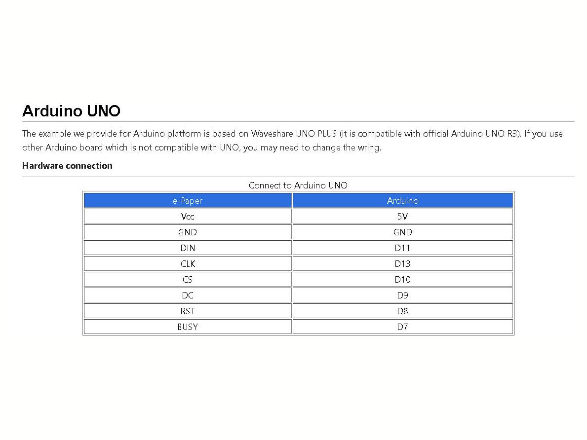
The wiki has also an example program for this which I used in Arduino :
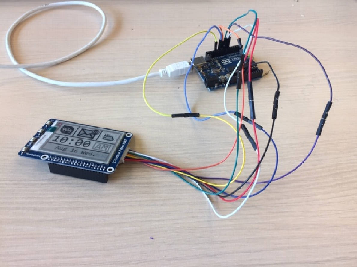
To make my own program and display a drum image, I went for further information about programming on these topics and Waveshare.
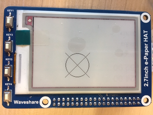
To understand the code, I made some tests by changing values and functions of the example code. Which gave this result :
Converting image to data
The following code makes reference to the imagedata.h library which uses imagedata.cpp :
#if 1
  /* This displays an image */
 /* Serial.print("show 2-gray image\r\n");
  epd.DisplayFrame(IMAGE_DATA);
  delay(1000);
#endif

#if 1
  Serial.print("show 4-gray image\r\n");
  epd.Init_4Gray();
  epd.Display4Gray(IMAGE_DATA_4Gray);
#endif
try with GIMP
I made some research to convert a SVG image to data with not much success. GIMP has a function which can convert it to C code. Looking like this :
static const struct {
  guint      width;
  guint      height;
  guint      bytes_per_pixel; /* 2:RGB16, 3:RGB, 4:RGBA */
  guint8     pixel_data[744 * 526 * 4 + 1];
}
gimp_image = {
744, 526, 4,
  "\377\377\377\377\377\377\377\377\377\377\377\377\377\377\377\377\377\377"
  "\377\377\377\377\377\377\377\377\377\377\377\377\377\377\377\377\377\377"
  "\377\377\377\377\377\377\377\377\377\377\377\377\377\377\377\377\377\377"
  "\377\377\377\377\377\377\377\377\377\377\377\377\377\377\377\377\377\377"
  "\377\377\377\377\377\377\377\377\377\377\377\377\377\377\377\377\377\377"
  "\377\377\377\377\377\377\377\377\377\377\377\377\377\377\377\377\377\377"
  "\377\377\377\377\377\377\377\377\377\377\377\377\377\377\377\377\377\377"
  "\377\377\377\377\377\377\377\377\377\377\377\377\377\377\377\377\377\377"
  "\377\377\377\377\377\377\377\377\377\377\377\377\377\377\377\377\377\377"
  "\377\377\377\377\377\377\377\377\377\377\377\377\377\377\377\377\377\377"
  "\377\377\377\377\377\377\377\377\377\377\377\377\377\377\377\377\377\377"
  "\377\377\377\377\377\377\377\377\377\377\377\377\377\377\377\377\377\377"
}
const unsigned char IMAGE_DATA[5808] PROGMEM = {
/* 0X00,0X01,0XB0,0X00,0X08,0X01, */
0XFF,0XFF,0XFF,0XFF,0XFF,0XFF,0XFF,0XFF,0XFE,0X1F,0XFF,0XFF,0XFF,0XFF,0XFF,0XFF,
0XE1,0XFF,0XFF,0XFF,0XFF,0XFF,0XFF,0XFF,0XFF,0XFF,0XFF,0XFF,0XFF,0XFF,0XFE,0X1F,
0XFF,0XFF,0XFF,0XFF,0XFF,0XFF,0XE1,0XFF,0XFF,0XFF,0XFF,0XFF,0XFF,0XFF,0XFF,0XFF,
0XFF,0XFF,0XFF,0XFF,0XFE,0X1F,0XFF,0XFF,0XFF,0XFF,0XFF,0XFF,0XE1,0XFF,0XFF,0XFF,
0XFF,0XFF,0XFF,0XFF,0XFF,0XFF,0XFF,0XFF,0XFF,0XFF,0XFE,0X1F,0XFF,0XFF,0XFF,0XFF,
0XFF,0XFF,0XE1,0XFF,0XFF,0XFF,0XFF,0XFF,0XFF,0XFF,0XFF,0XFF,0XFF,0XFF,0XFF,0XFF,
0XFE,0X1F,0XFF,0XFF,0XFF,0XFF,0XFF,0XFF,0XE1,0XFF,0XFF,0XFF,0XFF,0XFF,0XFF,0XFF,
0XFF,0XFF,0XFF,0XFF,0XFF,0XFF,0XFE,0X1F,0XFF,0XFF,0XFF,0XFF,0XFF,0XFF,0XE1,0XFF,
0XFF,0XFF,0XFF,0XFF,0XFF,0XFF,0XFF,0XFF,0XFF,0XFF,0XFF,0XFF,0XFE,0X1F,0XFF,0XFF,
0XFF,0XFF,0XFF,0XFF,0XE1,0XFF,0XFF,0XFF,0XFF,0XFF,0XFF,0XFF,0XFF,0XFF,0XFF,0XFF,
}
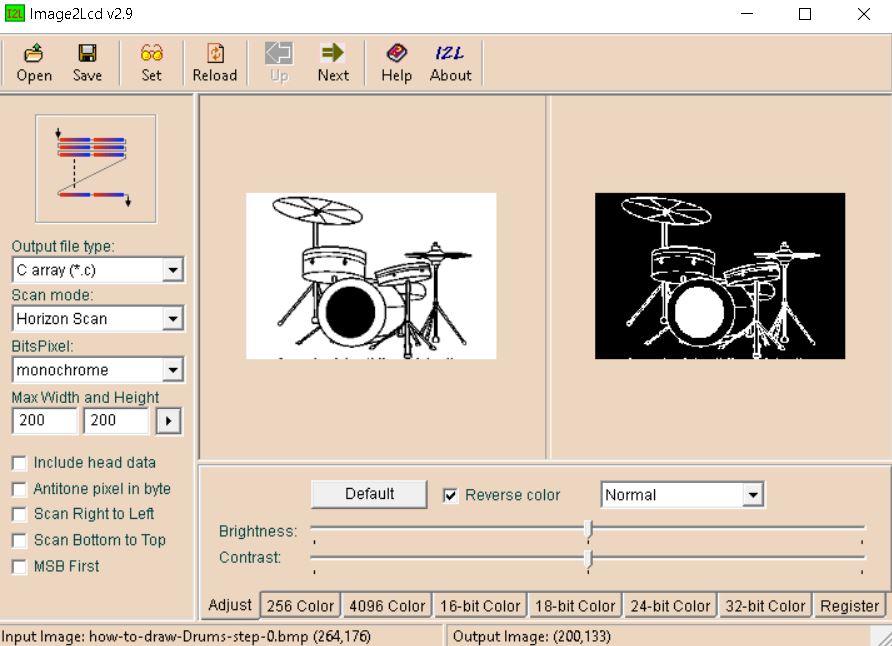
Then I looked into the e-ink display user manual which gives a way to do it :
After converting the image in monochrome with paint and resize it to the size of the display (264x176), open it with Image2LCD.exe and save it as .C file :
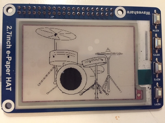
Then I copied the code into the imagedata.cpp file and enter the following code into the main arduino code :
Serial.print("show array\r\n");
epd.DisplayFrame(gImage_Drum_picture);
Then I need to declare the picture with #include "imagedata.h" in main code and extern const unsigned char gImage_Drum_picture[]; in imagedata.h
Here is the result :
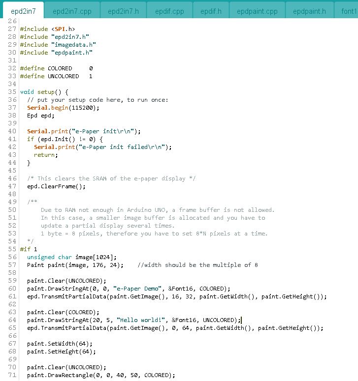
Drawing image with Arduino IDE
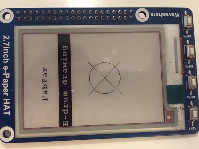
Then I looked how to draw an image directly with the Arduino IDE. We can write text. I’ve commented each line to describe the function :
Paint paint(image, 176, 24); // define the frame of image : first number = width, 2nd = height

paint.DrawStringAt(0, 0, "FabTar project", &Font16, COLORED); // this function write the text to x and y coordinates inside the paint() first number = x, 2nd number = y
The following function change the coordinates of the frame paint() :
epd.TransmitPartialData(paint.GetImage(), 16, 32, paint.GetWidth(), paint.GetHeight()); // the 2 numbers change the X and Y coordinates
I made a test with the following code :
#include <SPI.h>
#include "epd2in7.h"
#include "epdpaint.h"

#define COLORED     0
#define UNCOLORED   1

void setup() {
  // put your setup code here, to run once:
  Serial.begin(115200);
  Epd epd;

  Serial.print("e-Paper init\r\n");
  if (epd.Init() != 0) {
    Serial.print("e-Paper init failed\r\n");
    return;
  }

  /* This clears the SRAM of the e-paper display */
  epd.ClearFrame();

#if 1
  unsigned char image[1024];
  Paint paint(image, 176, 24);    //width should be the multiple of 8

  paint.Clear(UNCOLORED);
  paint.DrawStringAt(48, 0, "FabTar", &Font16, COLORED);
  epd.TransmitPartialData(paint.GetImage(), 0, 32, paint.GetWidth(), paint.GetHeight());

  paint.Clear(COLORED);
  paint.DrawStringAt(0, 5, "E-drum drawing", &Font16, UNCOLORED);
  epd.TransmitPartialData(paint.GetImage(), 0, 64, paint.GetWidth(), paint.GetHeight());

  Serial.print("show draw image\r\n");
  epd.DisplayFrame();
  delay(1000);
#endif
paint.DrawRectangle(0, 0, 40, 50, COLORED); // first 2 numbers X/Y coordinates of 1st point; other 2 numbers X/Y coordinates of 2nd point
paint.DrawLine(0, 0, 40, 50, COLORED); // first 2 numbers X/Y coordinates of 1st point; other 2 numbers X/Y coordinates of 2nd point
paint.DrawCircle(32, 32, 30, COLORED); // first 2 numbers X/Y radius and 3d is the center
paint.DrawFilledRectangle(0, 0, 40, 50, COLORED);
Here is the result :
Changing the image with a button
The cool thing about e-ink display is that the image can remain even when it is powered off. But if we power it on too long it can be damaged. So I don’t want it to refresh the picture each time the program starts the void loop(). I need to put into sleep mode the display and wake it up only when I push a button :
Looking into the epd2in7.cpp file, we have the epd.Sleep() and epd.Reset() for that. I wrote the following code to test it and looked on the serial monitor what’s happening :
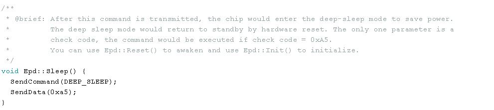
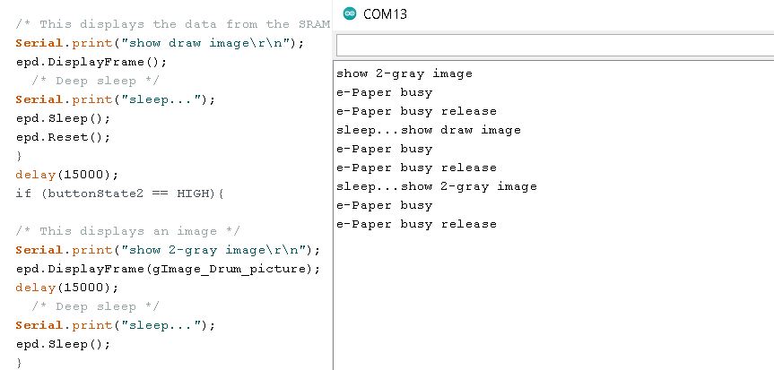
the code is running but the image on the display doesn’t refresh even after the reset function is called.
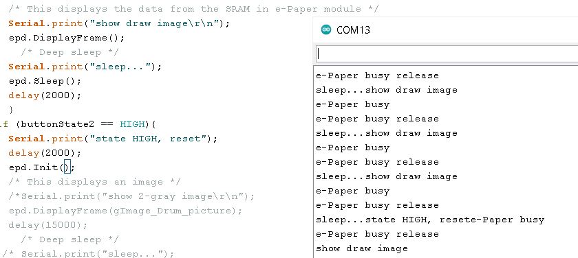
Looking on this github thread, I should call the function epd.Init() instead of epd.Reset to wake up the display from sleep. So I use the following code :
Drawing schematic
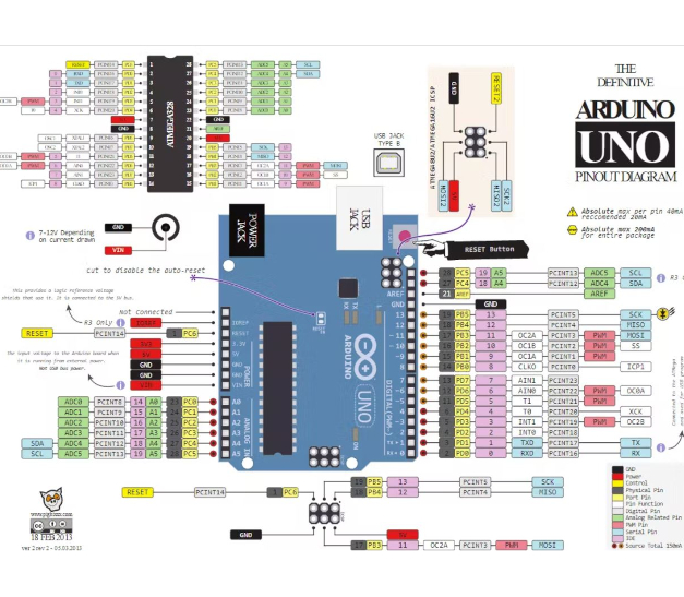
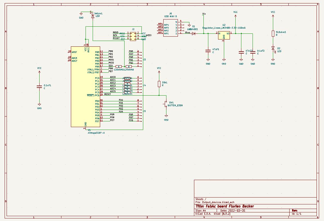
I plan to make a board which can use the display and also be useful for the INPUT week and my final project. I made a quick review of the Atmega 328p during the embedded programming week and with 8 ADC pin and 32 total pin, it seems good for my project. Besides it’s the MCU used for the Arduino Uno so it’s extensively documented.
I looked the Arduino eagle schematic to draw my own board :
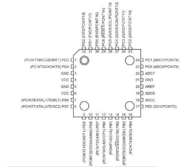
Also the pinout diagram 328 p was useful as well as the Arduino Uno pinout:
Minimal rules design :
-
Add a 10K resistance between Reset and Vcc
-
Button to Reset
-
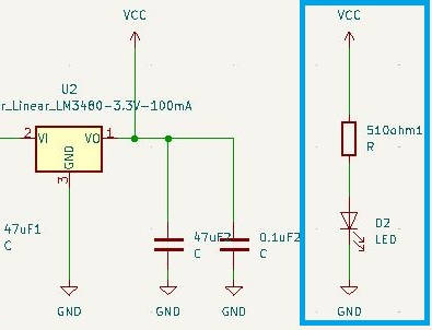
Add a capacitor of 0.1uF between Vcc and GND as close as possible to the pins.
-
Add a LED to test the board
-
Width of the trace 16mils (0.4mm) and distance between traces of 10mils (0.25mm)
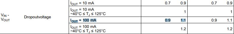
The e-ink display works with 3.3V so I need to add a voltage regulator (LDO) if I want to plug the board to my computer or any battery with higher voltage (the Atmega 328p has an operating voltage ranging from 2.7V to 5.5V):
This site gives a schematic for using a LDO.
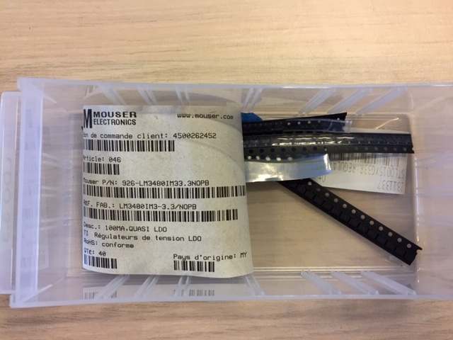
Looking at the LDO we have in the fablab. According to the datasheet, the dropoutvoltage is about 1.1V max meaning that a minimum of 4.4V is needed for Vin:
This week, I will experiment with KiCad to draw my board.
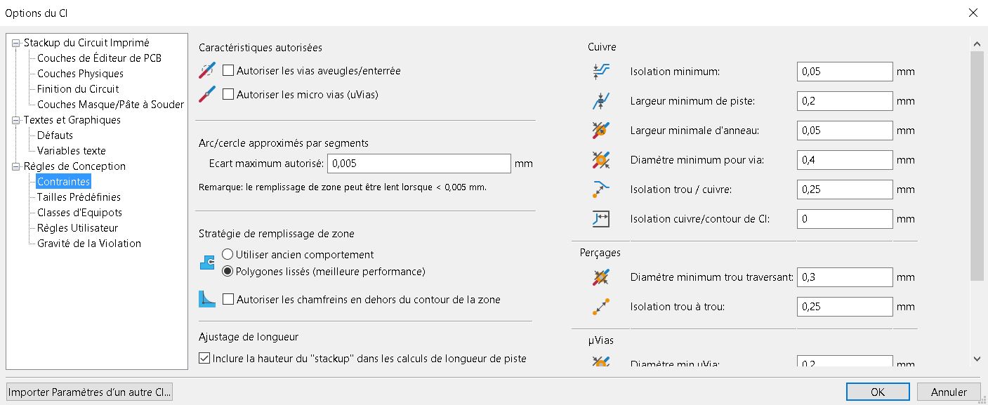
Looking at the documentation about KiCad. Adding the fablab library to start :
And defining the rules of conception :
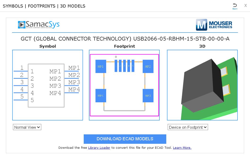
The symbol for mini USB type b was missing in the library. I added it via the mouser website which requires the library loader app to convert for KiCad format :
Quality of life things :
1- Resistors for future piezo input 2- LED for current detection 3-Jumpers (0 ohm resistor) and possibility to add jumper wires later
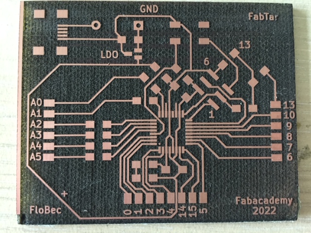
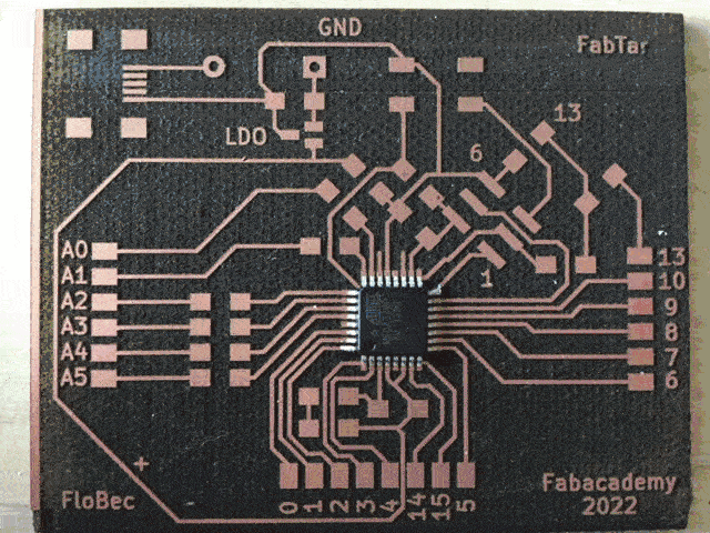
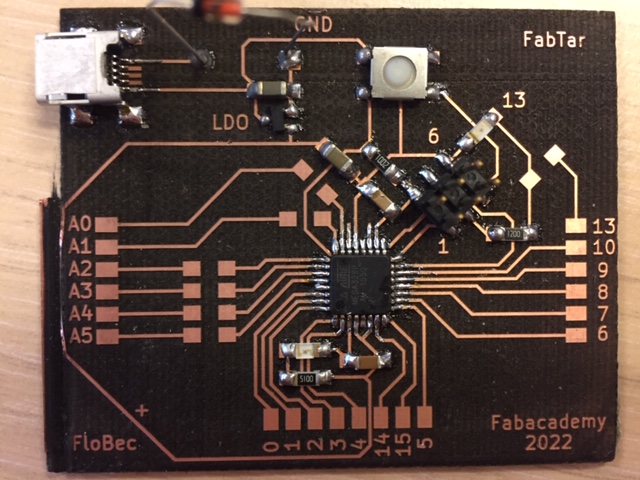
Finally the Schematic and the board done :
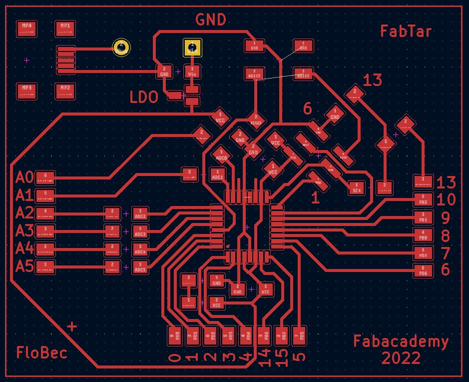
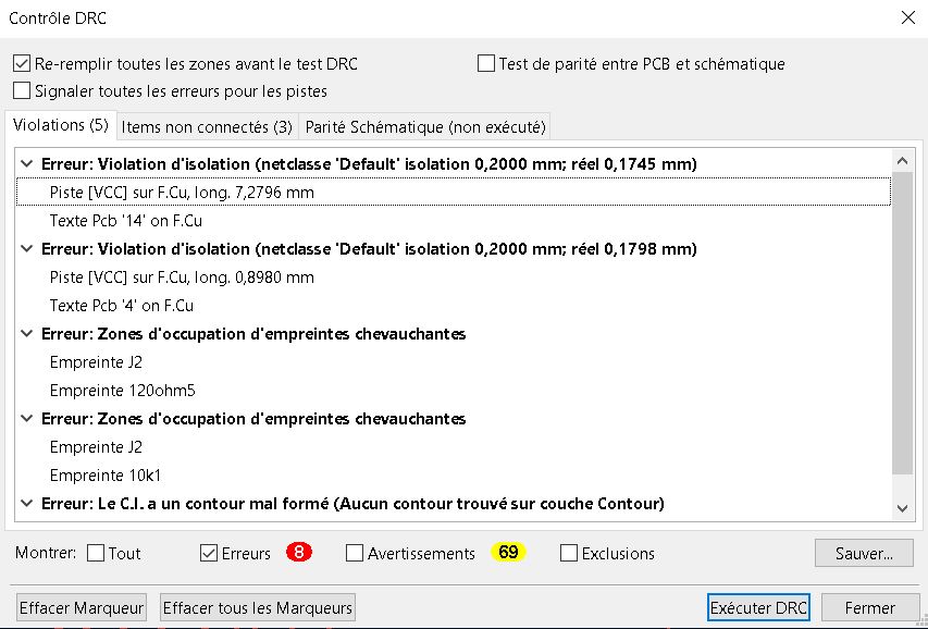
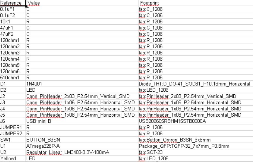
Looking at the DRC to find the errors. KiCad allows to make a Bill Of Materials (BOM) in csv format :
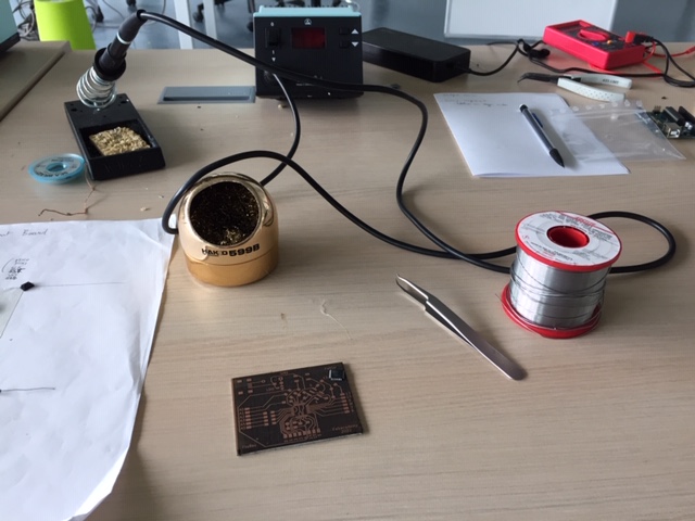
Engraving the card + soldering
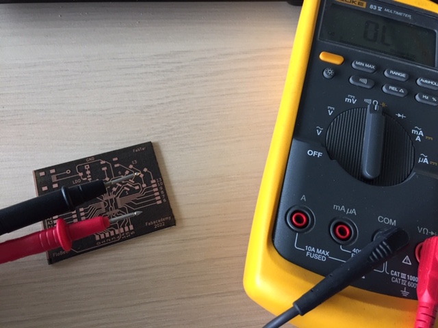
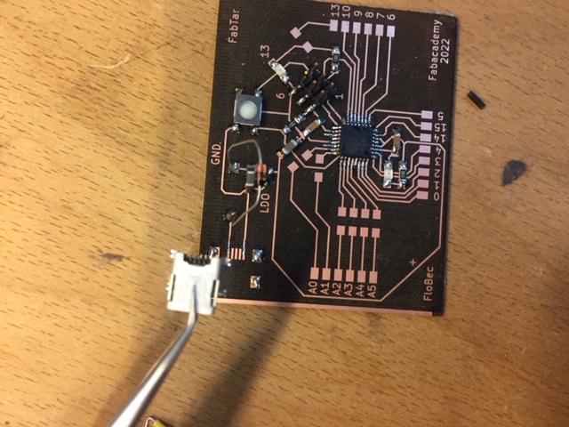
1st step : engraving the card + testing the circuit :
Soldering setup :
Soldering the board. Programming part plus LDO :
It doesn’t work. After testing the obvious problems like the orientation of the 6 pin header, we have current when the 6 pin header is plug in the programmer, but not when the USB mini is plug in. The problem is coming from the regulator of tension. It may be :
-
USB mini not plug in well enough
-
The diode from the tension regulator is not in the good orientation
-
The schema I made is not good
Fixing USB connector
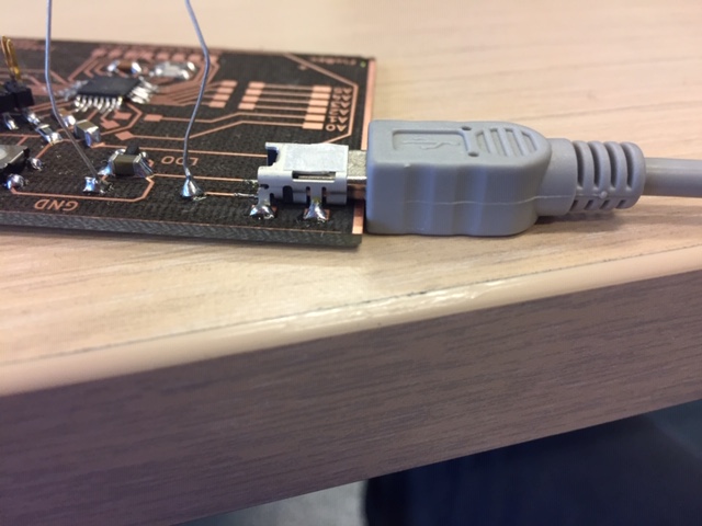
I removed it with a hot air convection rework tool :
Then laser cutting the board part on the edge. The laser went very close of the Vcc line but thankfully the connection was still good :
Changing the direction of the diode
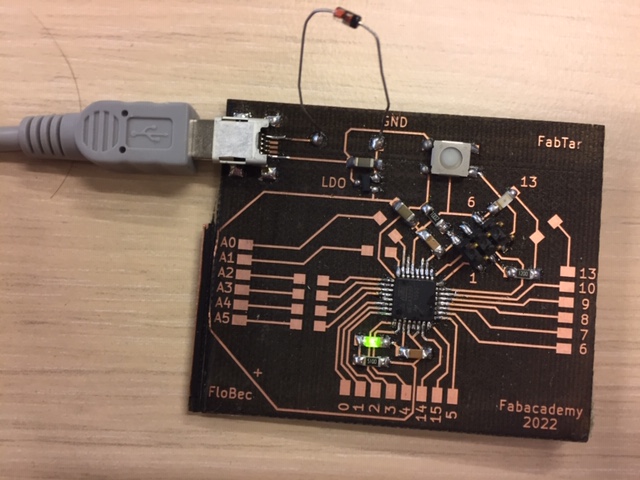
Now we have current, the tension regulator works :
I made a test with a blink led program :
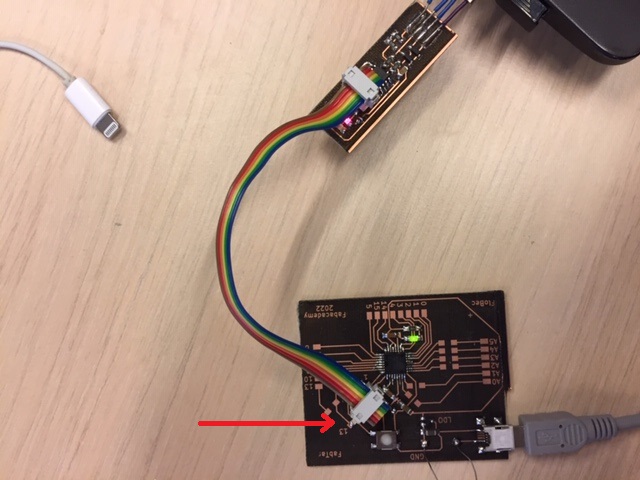
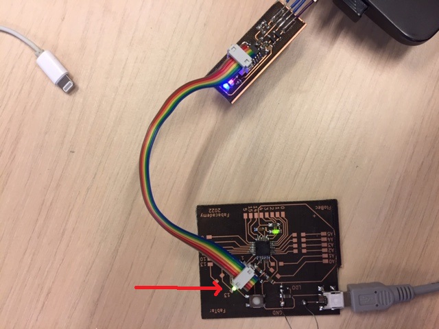
Now programming the board to display the example program :
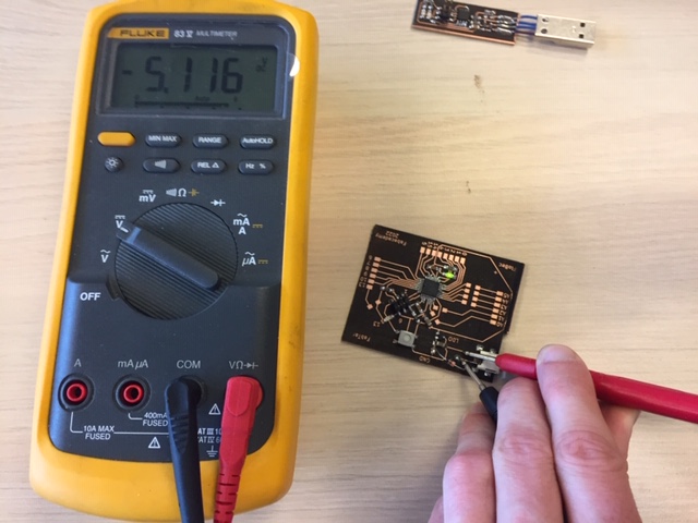
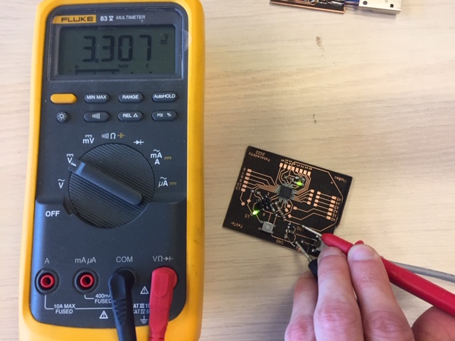
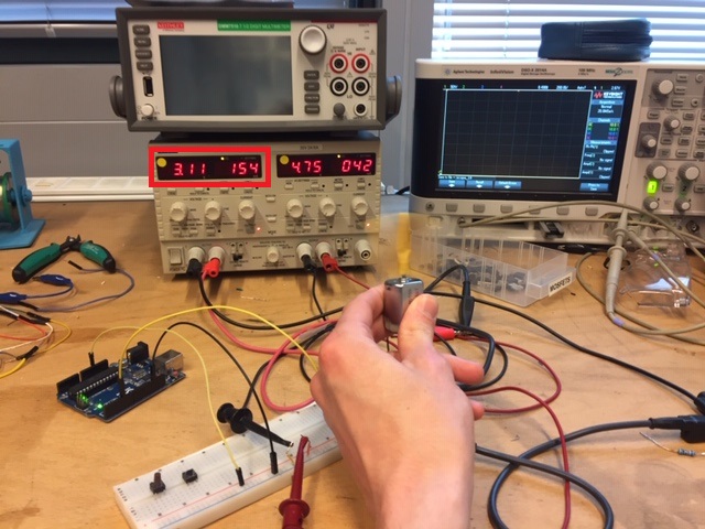
Group assignment
Test with the display
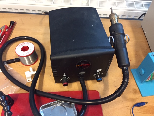
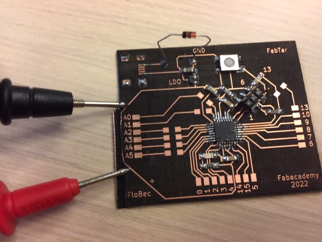
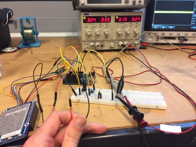
To test the power consumption of the display, I plug the circuit I made above to the power supply :
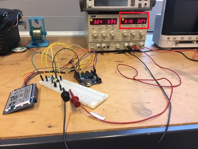
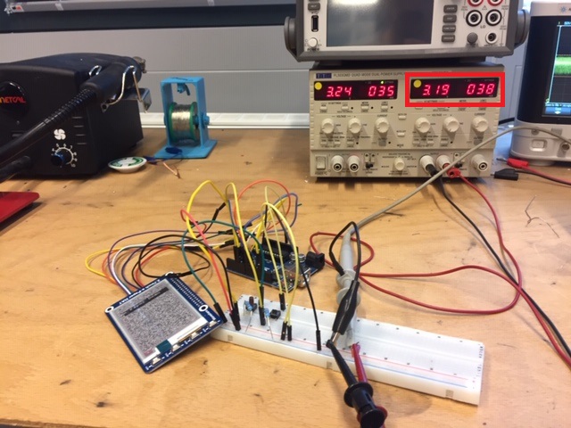
On the left picture, we have the current when sleep mode is on. On the right picture, the current when we push the button to change the image on the display. We can see that when the display is not plugged, the current is the same as above :
The e-ink display doesn’t consume power when on sleep mode. We calculate the power consumption of the circuit with the equation P = U x I
-
Power consumption when display is off : P = 3.19 x 0.024 = 0.076 W
-
Power consumption when the image change on the display : P = 3.19 x 0.038 = 0.121 W
Power consumption of the display alone P = 0.121 - 0.076 = 0.045 W
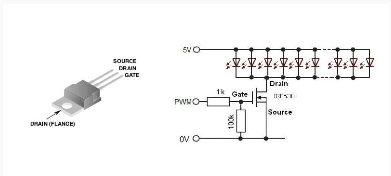
Test with a motor
To power the motor we need an external source of power. I used a MOSFET IRF520 to control the motor with the Arduino board. Adafruit gives the following schema for it :
To control the motor, I recycle the blink LED example of Arduino :
#define motor 5

// the setup function runs once when you press reset or power the board
void setup() {
  pinMode(motor, OUTPUT);
  digitalWrite(motor, LOW);
}

// the loop function runs over and over again forever
void loop() {
  digitalWrite(motor, HIGH);
  delay(5000);                       // wait for 5 seconds
  digitalWrite(motor, LOW);
  delay(5000);                       // wait for 5 seconds
}
The setup is the following :
On the picture, the power consumption of the motor is 0.48 W.