13. Input Devices
Assignment
individual assignment:
measure something: add a sensor to a microcontroller board that you have designed and read it
group assignment:
probe an input device’s analog levels and digital signals
Files :
Gantt plan of the week
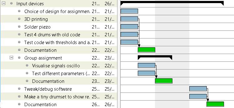
This week I plan to make drum pads with piezo-electric sensors following the work done in the Embedded programming week
Drum pads
Using piezo-electric sensor
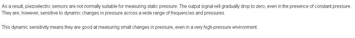
Piezo-electric sensors are used for measuring various parameters such as pressure, acceleration and temperature.
It generates an electrical charge when pressure is applied on the diaphragm. According to this page it’s best used for dynamic changes which is the case for drumming :
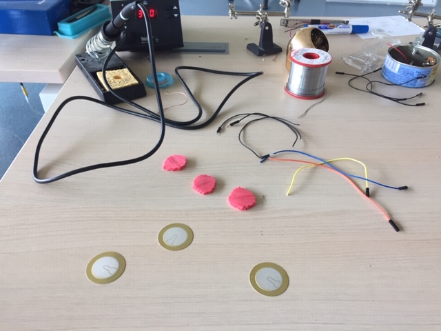
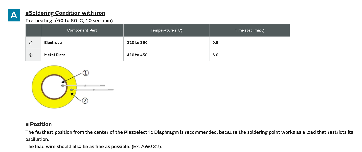
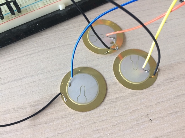
Soldering piezo
I looked for some tips on the internet to solder the piezo. The iron temperature is important to solder the wire to the electrode part without damaging it :
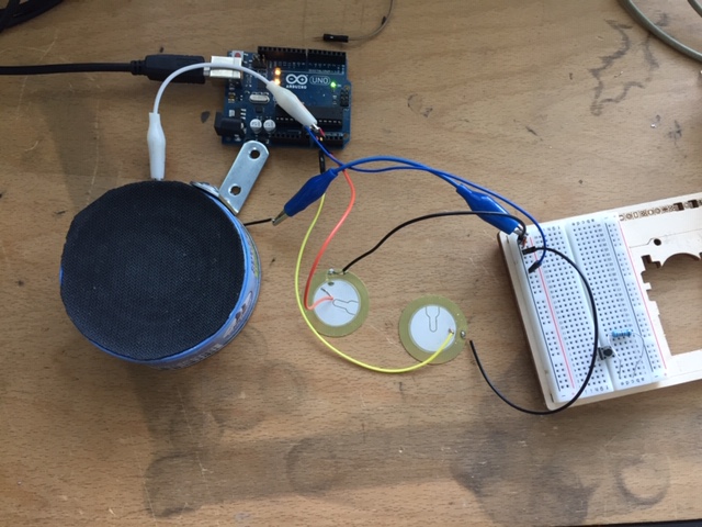
Board setup
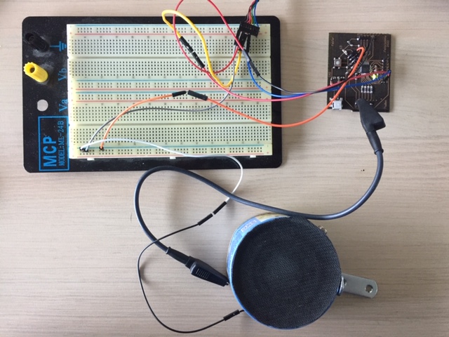
One of the wire of the piezo is connected to the analogic input and the other wire to the ground. I use an FTDI cable to connect the board to the computer (as explained in the electronic design week).
Arduino code
I used here a more simple code than in the Embedded programming week. And also used the board made on the Output devices week. This code sends a MIDI output in serial port if the piezo has been hit.
MIDI code
/* Florian Becker 23/04/22
This code sends a MIDI output in serial port if the piezo has been hit.

The program checks the value of an analogic pin. If it exceed a threshold we set a marker from 0 to 1.
Then it checks again the value of the analogic pin and if it's less than the threshold (to avoid sending several outputs for only one hit), it sends a MIDI note
*/

#include <MIDI.h>

MIDI_CREATE_DEFAULT_INSTANCE();

#define LED 13
#define PAD1 A2
#define PAD2 A3
#define PAD3 A4
#define PAD4 A5

int threshold = 380;                                     // threshold value going from 0 to 1023
byte note1 = 1;
byte note2 = 15;
byte note3 = 30;
byte note4 = 45;
int pad1hit = 0;

void setup() {
  // put your setup code here, to run once:
  Serial.begin(115200);
  MIDI.begin(4);
  pinMode(LED, OUTPUT);
}

void loop() {
  // put your main code here, to run repeatedly:
  if (analogRead(PAD1) >= threshold) {                    // if the value exceed the threshold, we say the pad has been hit
    pad1hit = 1;
    //Serial.print("max = ");
   //Serial.print(analogRead(PAD1));
  }
  if (pad1hit == 1 && analogRead(PAD1) <= (threshold - 100)){ // if the pad has been previously hit and the signal is diminishing, we send the note
    int volume1 = analogRead(PAD1);
    digitalWrite(LED, HIGH);
    //Serial.print("Volume1 =");
   //Serial.print(analogRead(PAD1));
    MIDI.sendNoteOn(note1, volume1, 1);
    MIDI.sendNoteOff(note1, 0, 1);
    volume1=0;
    pad1hit = 0;                                            // setting the marker padhit back to 0
  }
  digitalWrite(LED, LOW);
}
To make the test I added more sections for 3 other pads.
I also use the same setup described in the Embedded programming week with a DAW software (Ableton) and serial to MIDI converter.
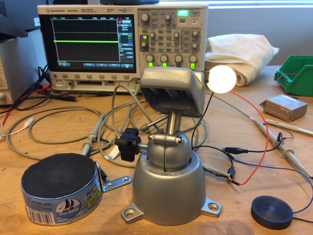
Group assignment
Test with 3 different configurations
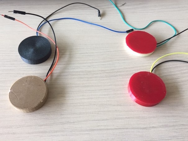
To test the analogical signal, I made a first experience with 3 piezo in different configurations
-
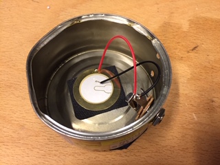
Metallic pad with a piezo and soft foam
-
Piezo without any pad
-
Piezo with a 3d printed pad (2mm thickness) in PLA
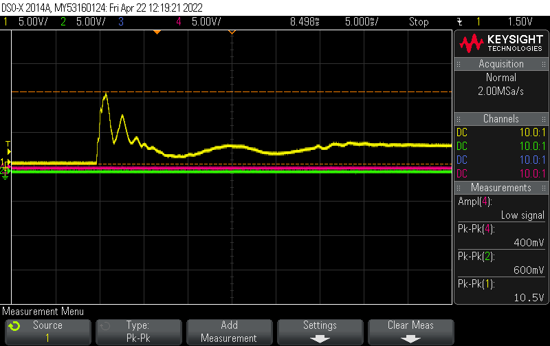
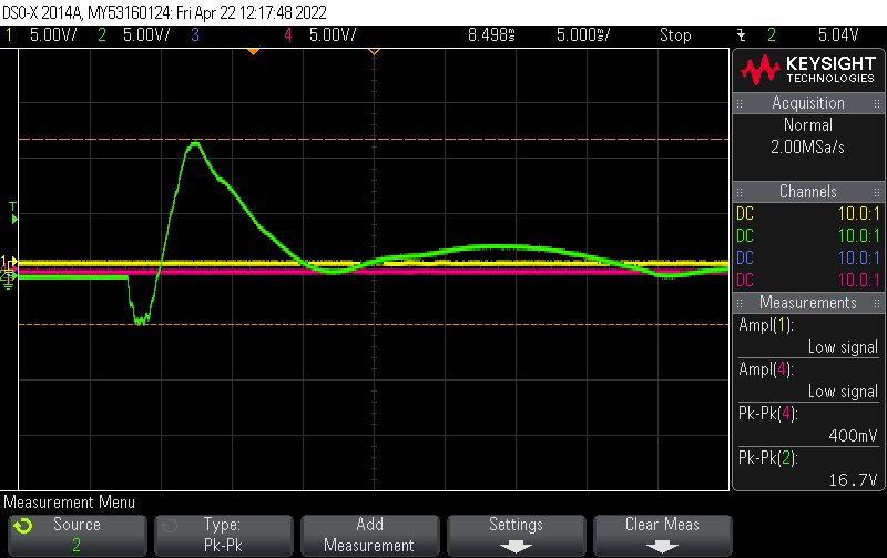
| Metallic pad with soft foam : 10.5V Peak to peak | Without any pad : 16.5 V Peak to peak | 3D printed pad : 6.2 V Peak to peak |
|---|---|---|
 |
 |
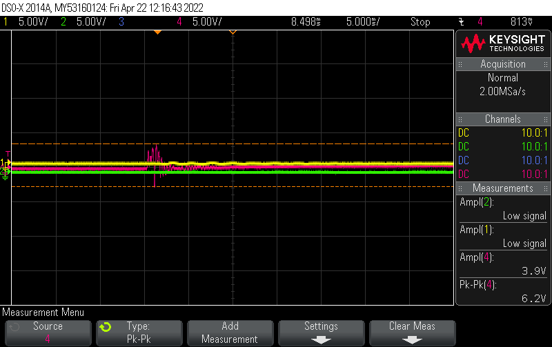 |
Results :
The 3D printed pad absorbed most of the force/signal. But the metallic pad with soft foam seems to transmit the force well enough.
Comparing analogical signal with oscilloscope and Arduino plotter
#define LED 13
#define PAD1 A0
#define PAD2 A1
#define PAD3 A2

int courbepad1 = 0;
int courbepad2 = 0;
int courbepad3 = 0;
int threshold = 380;

void setup() {
  // put your setup code here, to run once:
  Serial.begin(9600);
}

void loop() {
  courbepad1 = analogRead(PAD1);
  courbepad2 = analogRead(PAD2);
  courbepad3 = analogRead(PAD3);
  Serial.print(0);
  Serial.print("\t");
  Serial.print(1023);
  Serial.print("\t");
  Serial.println(courbepad1);
  Serial.print("\t");
  Serial.print(courbepad2);
  Serial.print("\t");
  Serial.print(courbepad3);
  Serial.print("\t");

  delay(25);
}
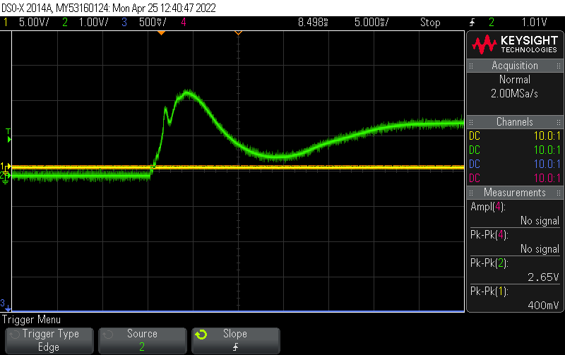
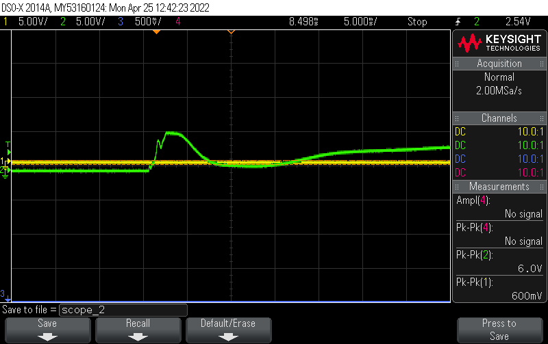
Setup configuration :
| Low force : 2.65 V Peak to peak | High force : 6 V Peak to peak |
|---|---|
 |
 |
 |
 |
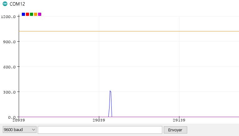
Results :
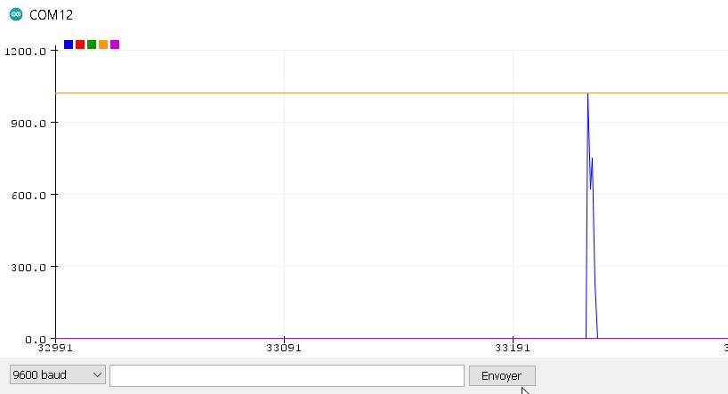
An input of 2.65 V corresponds to 380 on the arduino plotter. An input of 6V corresponds to more than the max on the plotter but I would need to make more test to confirm this…
Test with a motor
Following the advise of Jonah, I made a test with motors to have more rigorous approach.
Let’s go for a more scientific approach with observations, hypothesis, experience, results, interpretation and conclusion.
I made a test with 180 servo and 360 servo -> they have not enough speed to make a good hit.
I’ll test with NEMA 17 motors :
Controlling NEMA 17 motor with chillipeppr
Controlling it with JSON and Chillipeppr. Commands used :
$3ma=0 to set the 3d motor of tinyG to the X axis
$xvm=200 to set the speed of the X axis
G0 X1 to move to x = 1
I’m sending the most simple Gcode to go back and forth : G0 X1 G0 X0 G0 X1
I printed an arm in PLA for the occasion (with a 0.2 mm offset to fit the shaft) :
| 1st test : metallic pad | 2nd test : piezo only |
|---|---|
 |
 |
 |
 |
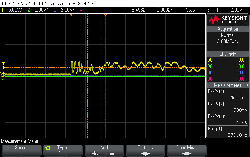
Observation :
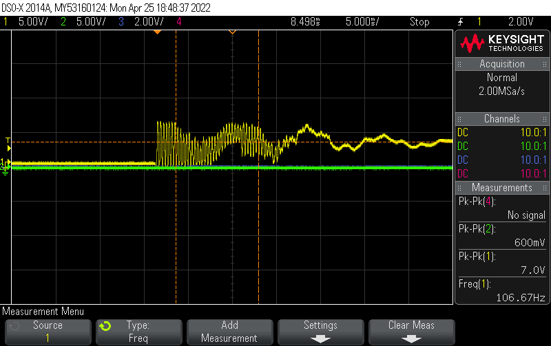
Each time, we can see the signal bounce. Here, there are two frequencies. The one catch by the oscilloscope is 106 Hz.
Hypothesis :
It may be due to the natural frequency of both the clamp and the piezo sensor.
Experience :
I’ll make more test with the same setup to see if the frequency is the same :
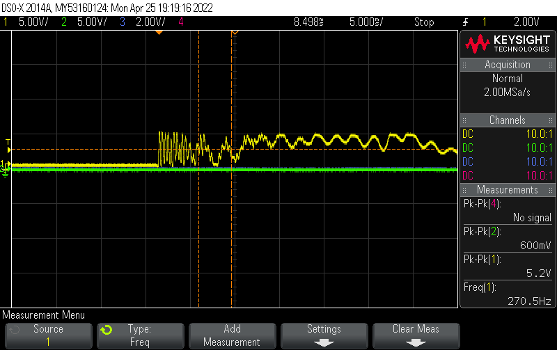
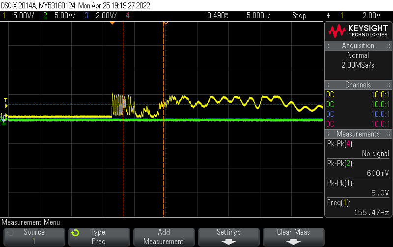
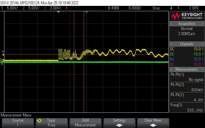
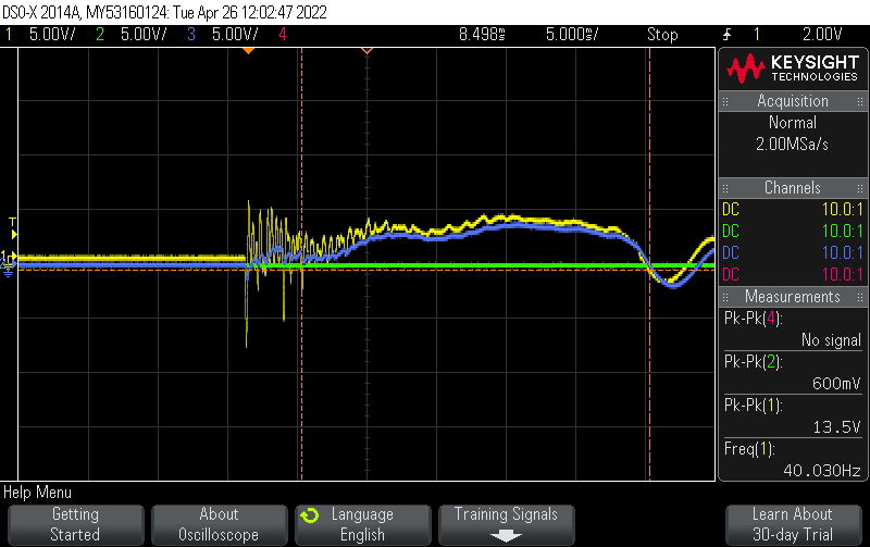
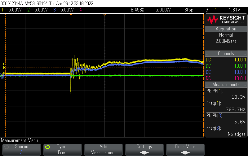
Results :
The big oscillations are between 155 Hz and 330 Hz.
Interpretation :
The oscillations seems to be always about the same range, around 300 Hz (the one with 155 Hz seems to not be a good catch by the oscillo). These oscillations would change for each configuration considering the natural frequency of the suface (piezo under a pad, piezo on the clamp or glued on another surface)
Conclusion :
For my final project, I may need to reduce this bounce.
For this I see two options :
-
Reduce it with some kind of shock absorber. It can be foam, or pads printed in TPU…
-
Reduce it with an electronic shock absorber : adding a capacitor with a RC circuit
Test with RC circuit
Observation :
There is an undesirable oscillation of the pad when hit
Hypthesis
It could be reduced by adding a RC circuit
Experience
I’ll test a low pass filter to see the effects on the bounce :

I’ll test 3 different cut-off frequency of 400 Hz, 280 Hz and 150 Hz to see the change :
For example :
Fc = 1/(2xPixRxC) -> RC = 5.6 E-4 for a Fc = 280 Hz
I have a capacity of 0.1 uF and I take a resistance of 5.6 Kohm.
| Cut-off frequency = 400 Hz | Cut-off frequency = 280 Hz | Cut-off frequency = 150 Hz |
|---|---|---|
| C=0.1uF, R=4kohm | C=0.1uF, R=5.6Kohm | C=0.1uF, R=11Kohm |
 |
 |
 |
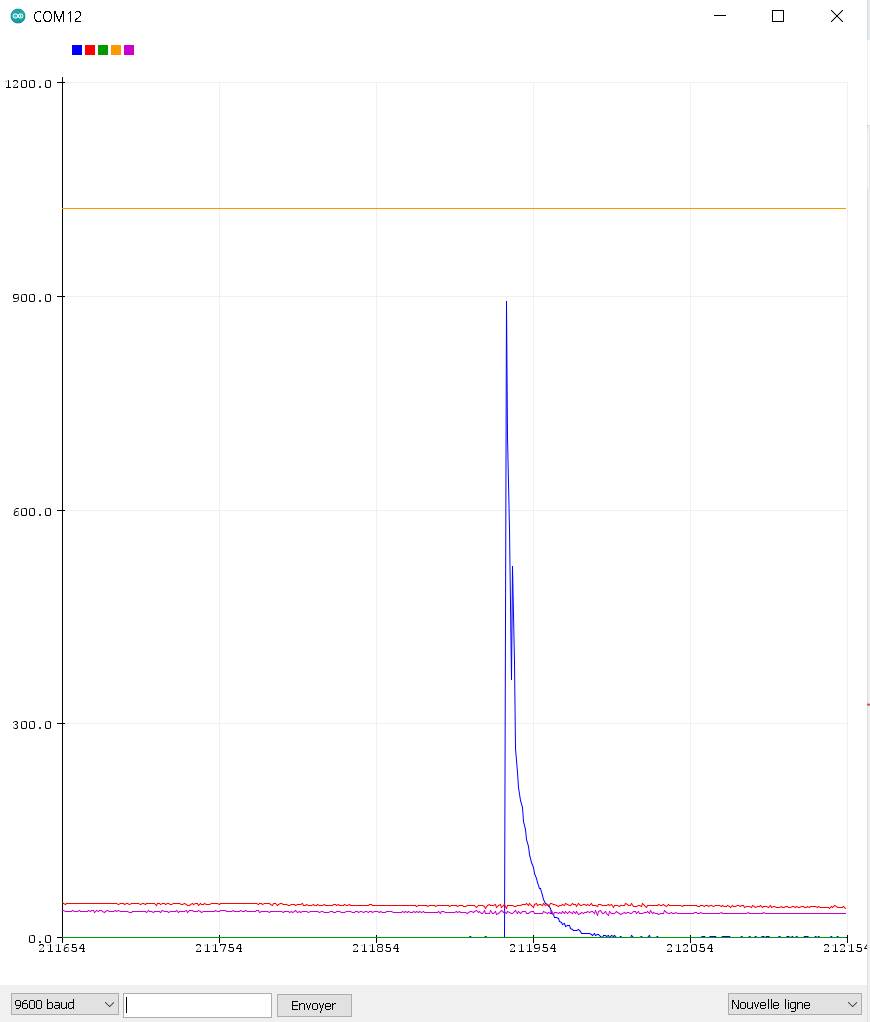
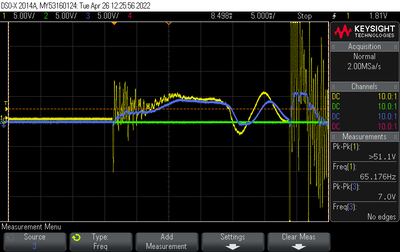
Results :
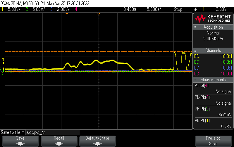
The amplitude of the high frequency oscillations is reduced after the RC circuit (in Blue) compared to the one before the RC circuit (in yellow). The yellow amplitude peaking at 51 V (!) with fast oscillations, while the blue one peaking at 7 V only.
Interpration
The RC circuit reduced the high frequency oscillations. But it also reduced the amplitude of the initial impact (And it induced also a small delay (less than 1ms)). To make this a proper test I should try with higher value of capacity and lower resistance.
Also there wasn’t much difference between the 3 tests because the high frequency the RC circuit cuts is much higher than 400 Hz.
Conclusion
The RC circuit did its job ! But it’s important to consider the value of the resistance to have a good initial impact.
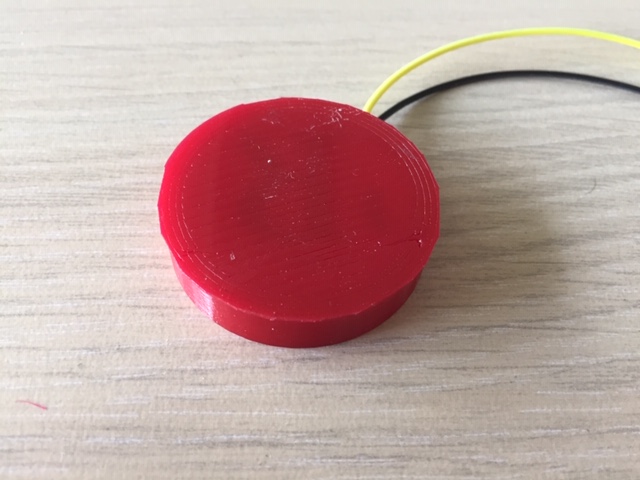
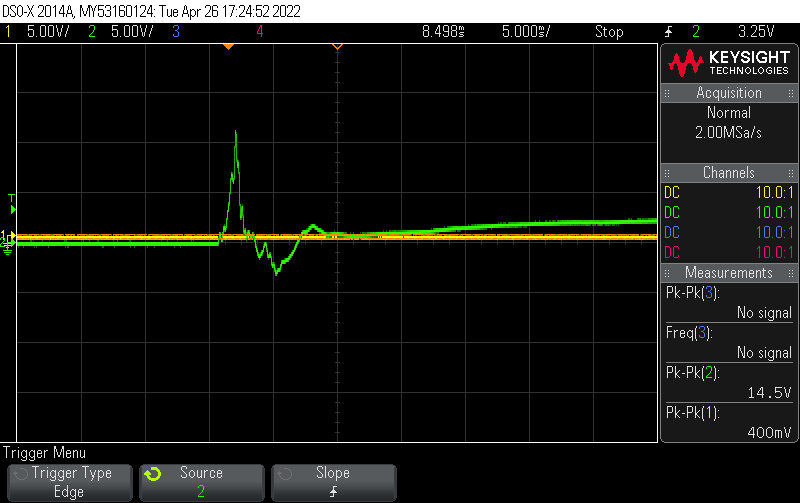
further tests with different materials :
Test with a finger strike. Using approximately the same force as in the first tests
| TPU pad with 2 mm thickness | Oscilloscope : 14.5 V Peak to peak |
|---|---|
 |
 |
| Bamboo pad with 1.5 mm thickness | Oscilloscope : 12.9 V Peak to peak |
|---|---|
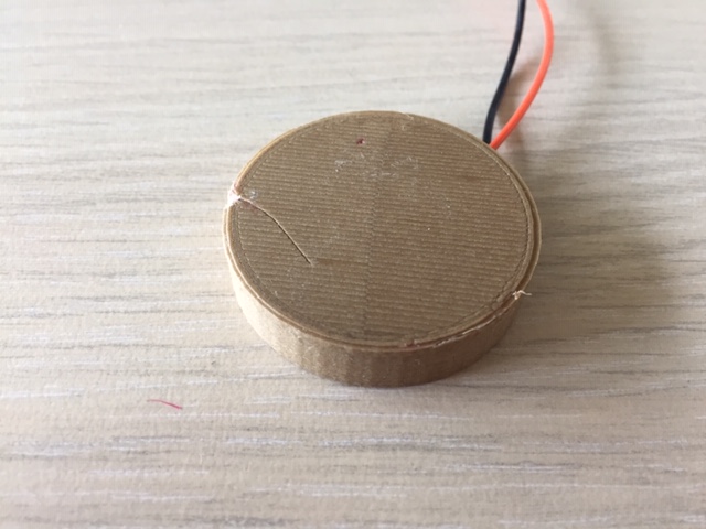 |
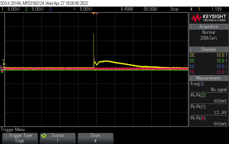 |
| Dual extrusion TPU and PVA with 1.5 mm thickness | Oscilloscope : 11.1 V Peak to peak |
|---|---|
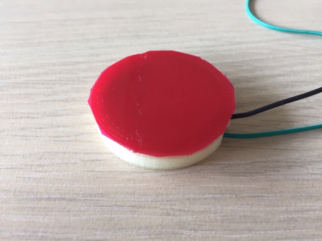 |
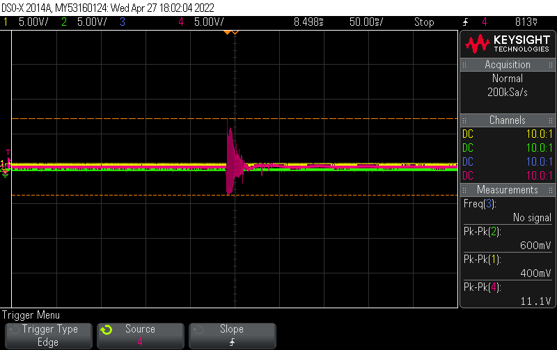 |
Conclusion
For the material used, TPU only seems to be the best one.
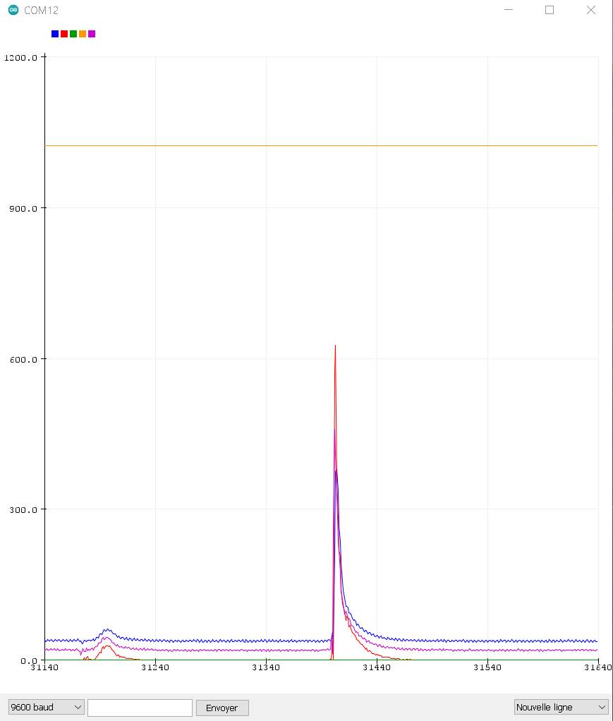
Considering the RC circuit, it’s good to reduce the oscillations. But looking on the Arduino plotter, it doesn’t have much oscillations. It seems that the mcu has some kind of integrated RC circuit to absorb the signal, otherwise the 51 V could kill it ! It could also be interesting to use a High pass filter to absorb the low frequency oscillations.
There are also big bounces which appears 25 ms to 40 ms later.
For my final project, I should consider :
-
Using a material that transmit the force without much oscillations : TPU is good
-
Using a RC circuit to absorb the undesirable oscillations and the potential high amplitudes.
-
Reduce the biggest bounces with a debounce timer in the code corresponding to the one seen on the oscillo.